EP0438208A2 - Buse à fente d'air rotative - Google Patents
Buse à fente d'air rotative Download PDFInfo
- Publication number
- EP0438208A2 EP0438208A2 EP91300020A EP91300020A EP0438208A2 EP 0438208 A2 EP0438208 A2 EP 0438208A2 EP 91300020 A EP91300020 A EP 91300020A EP 91300020 A EP91300020 A EP 91300020A EP 0438208 A2 EP0438208 A2 EP 0438208A2
- Authority
- EP
- European Patent Office
- Prior art keywords
- nozzle
- air
- rotatable
- slot nozzle
- slot
- Prior art date
- Legal status (The legal status is an assumption and is not a legal conclusion. Google has not performed a legal analysis and makes no representation as to the accuracy of the status listed.)
- Granted
Links
Images



Classifications
-
- B—PERFORMING OPERATIONS; TRANSPORTING
- B05—SPRAYING OR ATOMISING IN GENERAL; APPLYING FLUENT MATERIALS TO SURFACES, IN GENERAL
- B05C—APPARATUS FOR APPLYING FLUENT MATERIALS TO SURFACES, IN GENERAL
- B05C11/00—Component parts, details or accessories not specifically provided for in groups B05C1/00 - B05C9/00
- B05C11/02—Apparatus for spreading or distributing liquids or other fluent materials already applied to a surface ; Controlling means therefor; Control of the thickness of a coating by spreading or distributing liquids or other fluent materials already applied to the coated surface
- B05C11/06—Apparatus for spreading or distributing liquids or other fluent materials already applied to a surface ; Controlling means therefor; Control of the thickness of a coating by spreading or distributing liquids or other fluent materials already applied to the coated surface with a blast of gas or vapour
-
- G—PHYSICS
- G03—PHOTOGRAPHY; CINEMATOGRAPHY; ANALOGOUS TECHNIQUES USING WAVES OTHER THAN OPTICAL WAVES; ELECTROGRAPHY; HOLOGRAPHY
- G03C—PHOTOSENSITIVE MATERIALS FOR PHOTOGRAPHIC PURPOSES; PHOTOGRAPHIC PROCESSES, e.g. CINE, X-RAY, COLOUR, STEREO-PHOTOGRAPHIC PROCESSES; AUXILIARY PROCESSES IN PHOTOGRAPHY
- G03C1/00—Photosensitive materials
- G03C1/74—Applying photosensitive compositions to the base; Drying processes therefor
Definitions
- the present invention pertains to air bars for drying, and more particularly, pertains to an air bar with a rotatable slot nozzle for directional air flow control and diffusion.
- the present invention overcomes the disadvantages of the prior art by providing an air bar with a rotatable slot nozzle assembly which can be rotated to change the direction of air flow from the rotatable slot nozzle.
- the general purpose of the present invention is an air bar with a directionally rotatable slot nozzle in an inner rotatable baffle assembly.
- the rotatable baffle assembly and nozzle slot provide for adjusting the direction of the continuous impingement air slot on a coated web within a given zone, so as to profile the air flow to dry and set the coating of the web for the web flow direction.
- an air bar including a feed port, an outer nozzle housing and an inner rotatable baffle assembly with a longitudinal slot attached thereto.
- the outer nozzle housing includes solid ends.
- the inner rotatable baffle assembly including the longitudinal slot is rotatably secured between the ends, and located at substantially the center of the partial round outer nozzle housing, and extending to the inner circumference of the outer nozzle housing.
- Two rotatably aligned baffles are connected at a common vertex which is also the pivot access. Seal wipers are located at each edge of the partial round outer nozzle housing to seal against the inner rotatable baffle assembly.
- a rotatable slot nozzle air bar with an internal rotatable nozzle baffle assembly which provides a structure for varying air convection within a specific drying zone consisting of a plurality of said rotatable slot nozzles for profiling air impingement velocity within the zone for enhanced drying to set and dry a coating, such as a coating on a photosensitive film web.
- the slot nozzle assembly includes two aligned baffles and a slot nozzle aligned substantially perpendicularly to the baffles which pivot about a longitudinal axis of the rotatable baffle assembly.
- FIG. 1 illustrates a perspective view in partial cutaway of a rotatable slot nozzle air bar 10 with an adjustable baffle assembly 12 as later described in detail.
- the rotatable slot nozzle air bar 10 includes a rectangular distribution chamber 14 with a feed port 18 and a surrounding gasket flange 20 located on the top surface 22.
- the lower edges 24 and 26 of the top sides 28 and 30 of the distribution chamber 14 intersect a partially cylindrical nozzle housing 32.
- a plurality of holes 34a-34n are located in the upper portion of the nozzle housing 32 within the confines of the edges 24 and 26 of the distribution chamber 14.
- the adjustable baffle assembly 12 aligns within the inner periphery and along the central axis of the nozzle housing 32.
- the adjustable baffle assembly 12 includes a central rod 36 aligned and coinciding along the outer housing axis, and contiguous aligned holed baffle members 38 and 40 with an interceding "V" angle bend 42 between the holed baffle members 38 and 40 which aligns with and secures to the central rod 36.
- the baffles 38 and 40 include a plurality of air distribution holes 41a-41n. Rounded sections 44 and 46 secure to the outer ends of the holed baffle members 38 and 40, continue about a constant radius, and then are angled to form a continuous longitudinally aligned nozzle slot 48.
- the angled portions 44a and 46a extend radially from the rounded sections 44 and 46 to form the continuous nozzle slot 48, but may be formed angularly to obtain a desired nozzle air flow.
- Wiper seals 50 and 52 attach to the nozzle housing 32 and align at the lower edges 64 and 66, respectively, to seal against the outer periphery of rounded sections 44 and 46, respectively.
- End plates 54 (shown partially cutaway) and 56 extend vertically from the ends of the distribution chamber 14 across the opposing ends of the outer nozzle housing 32. Rotational movement of adjustable baffle assembly 12 is allowed between lower edges 64 and 66 of the nozzle housing 32. With a suitable design of nozzle housing 32 and adjustable baffle assembly 12, rotational movement in the range of 10° to 90° can be obtained by way of example and for purposes of illustration only and not to be construed as limiting of the present invention.
- FIG. 2A illustrates an end view of the rotatable slot nozzle air bar 10 where all numerals correspond to those elements previously described. Illustrated in particular is the end plate 54.
- the top portion 58 of the end plate 54 is generally rectangular in shape to conform to the shape of the distribution chamber 14, and the bottom portion 60 is generally round to conform to the end profile of the nozzle housing 32.
- the bottom portion 60 of the end plate 54 includes an edge 62 which aligns with the lower edges 64 and 66 of the nozzle housing 32.
- a wiper seal 53 is attached to the end plate 54 in line with edge 62 to seal against the baffle end plate 16 of the adjustable baffle assembly 12.
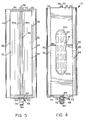
- a corresponding wiper seal 55 attaches to the opposing end plate 56 and against a baffle end plate 17 as also illustrated in FIG. 5.
- the rod 36 extends through a hole 67 in the end plate 54 and through a corresponding hole in the opposing end plate 56.
- a packing gland 69 is attached to the end plate 54 concentric to the hole 67 to seal the penetration of rod 36.
- End plate 56 is similar in construction and not illustrated for sake of brevity.
- FIG. 2B illustrates a cutaway end view in partial cross section of a rotatable slot nozzle air bar 10 where all numerals correspond to those elements previously described.
- the bottom portion 60 of the end plate 54 is cutaway for purposes of illustration to reveal the adjustable baffle assembly 12.
- Wiper seals 50 and 52 position at the lower edges 64 and 66 of the nozzle housing 32.
- the lower edges 64 and 66 are arcularly spaced to allow the nozzle slot 48 to be positionally rotated approximately along a 75° arc as illustrated by arc 71 as also illustrated by the dashed lines when rotated upwardly.
- FIG. 2C an alternative embodiment, illustrates a cutaway end view in partial cross section of a rotatable slot nozzle air bar assembly 10 where all numerals correspond to those elements previously described.
- the lower portion of the end plate 54 is cutaway for purposes of illustration to reveal the adjustable baffle assembly 12.
- the holed baffles 38 and 40 are angled upwardly towards each other to ultimately allow for a wider arcular swing of approximately 90° of the nozzle slot 48 along an arc 75 and between edges 64 and 66 which of course has a greater arcular spacing than that illustrated in FIG. 2B.
- This embodiment allows a range of rotation of the nozzle slot 48 from direct perpendicular impingement to nonimpinging induced flow at the web.
- FIG. 3 illustrates an end view of a bracket 68 where all numerals correspond to those elements previously described.
- the bracket 68 includes mounting flanges 70 and 72, and a raised planar portion 74 between the flanges.
- the bracket 68 aligns with the end plate 54 of the rotatable slot nozzle air bar 10 and is attached by screws or other suitable means.
- the rod 36 of FIG. 1 extends through the packing gland 69 and through a hole 79 in the raised planar portion 74 of the bracket 68 and secures into the adjustment handle 76 by means of a keyed fit and is retained by a pivot bolt 78 or other suitable means to allow for rotational adjustment of the baffles 38 and 40 which secure over and about the rod 36.
- a semicircular slot 80 is included in the raised planar portion 74 for accommodation of a threaded bolt 82 and a securing knob 84 which secure to the handle 76 in a predetermined position, thereby securing the baffles 38 and 40 in a predetermined position.
- FIG. 4 illustrates a top view of the rotatable slot nozzle air bar 10 where all numerals correspond to those elements previously described. Illustrated in particular is the bracket 68 aligned with the rotatable slot nozzle air bar 10 for rotational control of the adjustable baffle assembly 12 of FIG. 1 and nozzle slot 48 of FIG. 2 and also securing of the adjustable baffle assembly 12 and the nozzle slot 48 in a fixed position.
- a packing gland 73 aligns over the rod 36 and against the end plate 56.
- FIG. 5 illustrates a bottom view of the rotatable slot nozzle air bar 10 where all numerals correspond to those elements previously described.
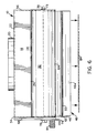
- FIG. 6 illustrates a rotatable slot nozzle air bar 10 aligned over a web 86.
- the rotatable slot nozzle 48 has been positioned to produce a desired impingement angle. Any impingement angle can be selected for the nozzle slot 48.
- FIG. 7 illustrates one of the modes of operation of the plurality of air bars 10 where all numerals correspond to those elements previously described.
- Air bars 10a and 10b each similar and like the air bar 10, align over and above the web 86.
- a plurality of air foils including air foils 88a, 88b and 88c are located on the underside of the web 86 to provide flotation.
- the web may be supported by other structures such as idler rolls.
- the air bar 10a is aligned above and between the air foils 88a and 88b, and the air bar 10b is aligned above and between the air foils 88b and 88c. This same alternating arrangement of the air bars and air foils continue along the length of the web for a desired distance.
- the air bars and air foils connect to headers for appropriate supply of air such as in a dryer like that disclosed in U.S. Patent No. 3,739,498, entitled "High Velocity Air Web Dryer", and assigned to the same assignee of this patent application by way of example and for purposes of illustration only and not to be construed as limiting of the present invention.
- the adjustable baffle assembly 12 is adjusted by the handle 76 as described in the previous figures to rotationally position the baffles to obtain the desired drying air flow out of the nozzle slot 48.
- Nozzle slot 48 of adjustable baffle assembly 12 in the air bar 10a is essentially positioned at the 6 o'clock position, causing air from the distribution chamber 14 to flow around and through the plurality of holes in baffles 38 and 40. The drying air impinges directly on web 86.
- the nozzle slot 48 is positioned at the 9 o'clock position, causing air from the diffusion plate to flow around the rounded section 44 and through the air distribution holes 41a-41n in baffles 38 and 40.
- a drying zone having a plurality of the rotatable slot nozzles is configured as illustrated in FIG. 7.
- adjustable baffle assembly 12 is positioned by means of adjustment handle 76 such that the jet from nozzle slot 48 is directed substantially parallel to the surface of web 86.
- the air jet does not impinge on the web surface and induces surrounding air into motion by entrainment, thereby effecting minimal air convection forces on the wet coating.
- Adjacent nozzles in the direction of web travel are similarly adjusted until the coating has set sufficiently so as to be tolerant of greater air convection forces without disturbance of the coating.
- Subsequent nozzles in the direction of web travel are adjusted so as to position their respective rotatable baffle assemblies to direct each air jet at progressively greater angles of incidence to the web.
- the angles may increase up to and including perpendicular impingement for increased heat and mass transfer effectiveness.
Landscapes
- Chemical & Material Sciences (AREA)
- Engineering & Computer Science (AREA)
- Materials Engineering (AREA)
- Physics & Mathematics (AREA)
- General Physics & Mathematics (AREA)
- Drying Of Solid Materials (AREA)
- Nozzles (AREA)
Applications Claiming Priority (2)
| Application Number | Priority Date | Filing Date | Title |
|---|---|---|---|
| US07/465,771 US5070628A (en) | 1990-01-16 | 1990-01-16 | Rotatable slot nozzle air bar |
| US465771 | 1990-01-16 |
Publications (3)
| Publication Number | Publication Date |
|---|---|
| EP0438208A2 true EP0438208A2 (fr) | 1991-07-24 |
| EP0438208A3 EP0438208A3 (en) | 1992-10-21 |
| EP0438208B1 EP0438208B1 (fr) | 1997-03-26 |
Family
ID=23849093
Family Applications (1)
| Application Number | Title | Priority Date | Filing Date |
|---|---|---|---|
| EP91300020A Expired - Lifetime EP0438208B1 (fr) | 1990-01-16 | 1991-01-02 | Buse à fente d'air rotative |
Country Status (5)
| Country | Link |
|---|---|
| US (1) | US5070628A (fr) |
| EP (1) | EP0438208B1 (fr) |
| JP (1) | JPH0623302A (fr) |
| CA (1) | CA2034105A1 (fr) |
| DE (1) | DE69125297T2 (fr) |
Cited By (2)
| Publication number | Priority date | Publication date | Assignee | Title |
|---|---|---|---|---|
| EP1666825A2 (fr) * | 2002-12-20 | 2006-06-07 | Andritz Technology and Asset Management GmbH | Dispositif de séchage ou traitement thermique d'une matière en bande |
| GB2428572A (en) * | 2005-07-30 | 2007-02-07 | Dyson Technology Ltd | Drying apparatus |
Families Citing this family (33)
| Publication number | Priority date | Publication date | Assignee | Title |
|---|---|---|---|---|
| US6096169A (en) * | 1996-05-14 | 2000-08-01 | Kimberly-Clark Worldwide, Inc. | Method for making cellulosic web with reduced energy input |
| US6149767A (en) * | 1997-10-31 | 2000-11-21 | Kimberly-Clark Worldwide, Inc. | Method for making soft tissue |
| US6083346A (en) * | 1996-05-14 | 2000-07-04 | Kimberly-Clark Worldwide, Inc. | Method of dewatering wet web using an integrally sealed air press |
| US6143135A (en) * | 1996-05-14 | 2000-11-07 | Kimberly-Clark Worldwide, Inc. | Air press for dewatering a wet web |
| US6187137B1 (en) | 1997-10-31 | 2001-02-13 | Kimberly-Clark Worldwide, Inc. | Method of producing low density resilient webs |
| US6197154B1 (en) | 1997-10-31 | 2001-03-06 | Kimberly-Clark Worldwide, Inc. | Low density resilient webs and methods of making such webs |
| US6306257B1 (en) | 1998-06-17 | 2001-10-23 | Kimberly-Clark Worldwide, Inc. | Air press for dewatering a wet web |
| US6280573B1 (en) | 1998-08-12 | 2001-08-28 | Kimberly-Clark Worldwide, Inc. | Leakage control system for treatment of moving webs |
| US6735883B1 (en) | 1999-10-15 | 2004-05-18 | Megtec Systems, Inc. | Electrostatic assisted web cooling and remoistening device |
| US6318727B1 (en) | 1999-11-05 | 2001-11-20 | Kimberly-Clark Worldwide, Inc. | Apparatus for maintaining a fluid seal with a moving substrate |
| US6397495B1 (en) * | 1999-12-30 | 2002-06-04 | Heidelberger Druckmaschinen Ag | Web steering air flotation device for printing equipment |
| US6775925B2 (en) | 2000-05-17 | 2004-08-17 | Megtec Systems Inc. | Water spray web cooling apparatus for web dryer |
| AU2001257629A1 (en) * | 2000-05-17 | 2001-11-26 | Megtec Systems, Inc. | Water spray web cooling apparatus for web dryer |
| US6484418B1 (en) | 2000-11-06 | 2002-11-26 | Kimberly-Clark Worldwide, Inc. | Yankee drying hood and method comprising angled impingement nozzles |
| US6533217B2 (en) | 2001-03-20 | 2003-03-18 | Faustel, Inc. | Web-processing apparatus |
| US6708919B2 (en) | 2002-03-19 | 2004-03-23 | Kimberly-Clark Worldwide, Inc. | Turning bar assembly for use with a moving web |
| JP4551117B2 (ja) * | 2004-04-28 | 2010-09-22 | 株式会社アトマックス | 微粒子噴霧装置 |
| US7311234B2 (en) * | 2005-06-06 | 2007-12-25 | The Procter & Gamble Company | Vectored air web handling apparatus |
| US7694433B2 (en) | 2005-06-08 | 2010-04-13 | The Procter & Gamble Company | Web handling apparatus and process for providing steam to a web material |
| GB0515750D0 (en) | 2005-07-30 | 2005-09-07 | Dyson Technology Ltd | Drying apparatus |
| GB0515754D0 (en) | 2005-07-30 | 2005-09-07 | Dyson Technology Ltd | Drying apparatus |
| GB2428569B (en) | 2005-07-30 | 2009-04-29 | Dyson Technology Ltd | Dryer |
| GB2434094A (en) | 2006-01-12 | 2007-07-18 | Dyson Technology Ltd | Drying apparatus with sound-absorbing material |
| CN102099105A (zh) | 2008-07-15 | 2011-06-15 | 特洛伊科技有限公司 | 流体处理系统 |
| US8882258B2 (en) * | 2012-05-03 | 2014-11-11 | Delphax Technologies Inc. | Web inkjet printing method and apparatus using an air bar |
| KR102196313B1 (ko) * | 2014-08-12 | 2020-12-29 | 엘지전자 주식회사 | 의류처리장치 |
| US10265801B2 (en) * | 2015-01-09 | 2019-04-23 | The Boeing Company | Rotating shielding devices |
| WO2017170714A1 (fr) * | 2016-03-29 | 2017-10-05 | 新日鐵住金株式会社 | Appareil d'élimination de liquide et procédé d'élimination de liquide |
| US10842095B2 (en) | 2017-07-18 | 2020-11-24 | Kalera, Inc. | Hydroponics apparatus, system and method |
| KR20200098115A (ko) * | 2019-02-12 | 2020-08-20 | 삼성전자주식회사 | 건조기 |
| KR102204208B1 (ko) * | 2019-11-21 | 2021-01-19 | 조영식 | 커피 머신의 디스케일링 장치 |
| CN112708950B (zh) * | 2020-12-08 | 2021-12-21 | 中国纺织科学研究院有限公司 | 纤维气体干燥装置及纤维气体干燥方法 |
| KR20240154352A (ko) * | 2023-04-18 | 2024-10-25 | 에스케이온 주식회사 | 디스펜싱된 점성유체의 검사와 리페어를 수행하는 장치 및 방법 |
Family Cites Families (11)
| Publication number | Priority date | Publication date | Assignee | Title |
|---|---|---|---|---|
| US1150540A (en) * | 1913-12-08 | 1915-08-17 | B F Sturtevant Co | Drying apparatus. |
| US1144896A (en) * | 1914-08-29 | 1915-06-29 | Alfred Thomas Fosbraey | Coated-paper-drying apparatus. |
| DE1039466B (de) * | 1957-04-05 | 1958-09-25 | Krantz Soehne H | Anordnung bei Spann- und Trocken-maschinen fuer Gewebebahnen, insbesondere bei Duesenspannrahmen, zur Verhuetung des Austritts des Trocken- bzw. Behandlungsmittels |
| DE1410879A1 (de) * | 1960-02-24 | 1968-10-24 | Fr Drabert Soehne | Trockeneinrichtung,insbesondere zum Trocknen von Geweben |
| GB1024671A (en) * | 1962-05-30 | 1966-03-30 | Bristol Fan Company Ltd | Drying nozzle |
| DE1460730B1 (de) * | 1963-12-06 | 1969-09-11 | Brueckner Kg Kurt Trockentech | Regelbare Düsenanordnung |
| US3272176A (en) * | 1964-04-13 | 1966-09-13 | Du Pont | Air knife |
| JPS5210337Y1 (fr) * | 1970-10-12 | 1977-03-05 | ||
| US3771236A (en) * | 1971-01-12 | 1973-11-13 | R Candor | Method and apparatus for treating sheet-like material with fluid |
| AT363320B (de) * | 1978-02-03 | 1981-07-27 | Walli Papier Zellstoffwatte | Durchstroemungstrockner zum trocknen eines faservlieses oder einer papierbahn |
| US4869157A (en) * | 1988-10-17 | 1989-09-26 | Hungerford John W | Modular air bar |
-
1990
- 1990-01-16 US US07/465,771 patent/US5070628A/en not_active Expired - Lifetime
-
1991
- 1991-01-02 EP EP91300020A patent/EP0438208B1/fr not_active Expired - Lifetime
- 1991-01-02 DE DE69125297T patent/DE69125297T2/de not_active Expired - Fee Related
- 1991-01-14 CA CA002034105A patent/CA2034105A1/fr not_active Abandoned
- 1991-01-16 JP JP3003358A patent/JPH0623302A/ja active Pending
Cited By (3)
| Publication number | Priority date | Publication date | Assignee | Title |
|---|---|---|---|---|
| EP1666825A2 (fr) * | 2002-12-20 | 2006-06-07 | Andritz Technology and Asset Management GmbH | Dispositif de séchage ou traitement thermique d'une matière en bande |
| GB2428572A (en) * | 2005-07-30 | 2007-02-07 | Dyson Technology Ltd | Drying apparatus |
| GB2428572B (en) * | 2005-07-30 | 2010-12-29 | Dyson Technology Ltd | Drying apparatus |
Also Published As
| Publication number | Publication date |
|---|---|
| DE69125297D1 (de) | 1997-04-30 |
| EP0438208B1 (fr) | 1997-03-26 |
| EP0438208A3 (en) | 1992-10-21 |
| US5070628A (en) | 1991-12-10 |
| CA2034105A1 (fr) | 1991-07-17 |
| DE69125297T2 (de) | 1997-07-17 |
| JPH0623302A (ja) | 1994-02-01 |
Similar Documents
| Publication | Publication Date | Title |
|---|---|---|
| US5070628A (en) | Rotatable slot nozzle air bar | |
| US5070627A (en) | Directional diffusion nozzle air bar | |
| US4069595A (en) | Arrangement for conveying web material through a treating plant | |
| US5105562A (en) | Web dryer apparatus having ventilating and impingement air bar assemblies | |
| US4787547A (en) | Mounting means for air bars | |
| EP0816786B1 (fr) | Une méthode de sechage d'un tissu revêté en movement évitant des tâches dans les revêtements à base de solvant | |
| EP0568301B1 (fr) | Dispositif de guidage à air avec plaque arrière pour une bande en mouvement | |
| FI60303C (fi) | Foerfarande och anordning foer styrning av ur en luftgenomslaepplig speciellt perforerad yta utstroemmande luftstroemmar | |
| US4425869A (en) | Fluid flow control mechanism for circuit board processing apparatus | |
| US4607590A (en) | Apparatus for directing fluid stream against substrate sheet | |
| GB2126974A (en) | Device for supporting a web on a bed of air | |
| JP2612625B2 (ja) | 空気支持型の中心案内装置とその方法 | |
| JPH10156249A5 (fr) | ||
| JP3416598B2 (ja) | 塗工装置 | |
| US5570519A (en) | Method and device in contact-free treatment of a web | |
| US4417540A (en) | Coating apparatus with air-nozzle arrangement | |
| JP2000503383A (ja) | フローティングドライヤ | |
| JP4569021B2 (ja) | エア吹出ノズルのエア吹出口長手幅調整装置 | |
| JP2501904Y2 (ja) | ファウンテンコ―タ装置 | |
| JPH0112155Y2 (fr) | ||
| JP2584923Y2 (ja) | 塗工装置 | |
| SU732641A1 (ru) | Распылитель дл паст в сушильных установках | |
| FI73151B (fi) | Faestarrangemang foer bladet eller motsvarande utjaemningsorgan i en belaeggningsanordning foer en materialbana. | |
| JP3824447B2 (ja) | カーテン塗工装置 | |
| JP2530998Y2 (ja) | 塗工装置 |
Legal Events
| Date | Code | Title | Description |
|---|---|---|---|
| PUAI | Public reference made under article 153(3) epc to a published international application that has entered the european phase |
Free format text: ORIGINAL CODE: 0009012 |
|
| AK | Designated contracting states |
Kind code of ref document: A2 Designated state(s): DE FR GB IT |
|
| PUAL | Search report despatched |
Free format text: ORIGINAL CODE: 0009013 |
|
| AK | Designated contracting states |
Kind code of ref document: A3 Designated state(s): DE FR GB IT |
|
| 17P | Request for examination filed |
Effective date: 19930310 |
|
| 17Q | First examination report despatched |
Effective date: 19950908 |
|
| GRAG | Despatch of communication of intention to grant |
Free format text: ORIGINAL CODE: EPIDOS AGRA |
|
| GRAH | Despatch of communication of intention to grant a patent |
Free format text: ORIGINAL CODE: EPIDOS IGRA |
|
| GRAH | Despatch of communication of intention to grant a patent |
Free format text: ORIGINAL CODE: EPIDOS IGRA |
|
| GRAA | (expected) grant |
Free format text: ORIGINAL CODE: 0009210 |
|
| AK | Designated contracting states |
Kind code of ref document: B1 Designated state(s): DE FR GB IT |
|
| PG25 | Lapsed in a contracting state [announced via postgrant information from national office to epo] |
Ref country code: FR Free format text: THE PATENT HAS BEEN ANNULLED BY A DECISION OF A NATIONAL AUTHORITY Effective date: 19970326 |
|
| REF | Corresponds to: |
Ref document number: 69125297 Country of ref document: DE Date of ref document: 19970430 |
|
| ET | Fr: translation filed | ||
| PG25 | Lapsed in a contracting state [announced via postgrant information from national office to epo] |
Ref country code: GB Free format text: LAPSE BECAUSE OF NON-PAYMENT OF DUE FEES Effective date: 19980102 |
|
| PLBE | No opposition filed within time limit |
Free format text: ORIGINAL CODE: 0009261 |
|
| STAA | Information on the status of an ep patent application or granted ep patent |
Free format text: STATUS: NO OPPOSITION FILED WITHIN TIME LIMIT |
|
| 26N | No opposition filed | ||
| GBPC | Gb: european patent ceased through non-payment of renewal fee |
Effective date: 19980102 |
|
| PG25 | Lapsed in a contracting state [announced via postgrant information from national office to epo] |
Ref country code: DE Free format text: LAPSE BECAUSE OF NON-PAYMENT OF DUE FEES Effective date: 19981001 |
|
| REG | Reference to a national code |
Ref country code: FR Ref legal event code: TP |
|
| REG | Reference to a national code |
Ref country code: FR Ref legal event code: ST |
|
| PG25 | Lapsed in a contracting state [announced via postgrant information from national office to epo] |
Ref country code: IT Free format text: LAPSE BECAUSE OF NON-PAYMENT OF DUE FEES;WARNING: LAPSES OF ITALIAN PATENTS WITH EFFECTIVE DATE BEFORE 2007 MAY HAVE OCCURRED AT ANY TIME BEFORE 2007. THE CORRECT EFFECTIVE DATE MAY BE DIFFERENT FROM THE ONE RECORDED. Effective date: 20050102 |