WO2017170714A1 - Appareil d'élimination de liquide et procédé d'élimination de liquide - Google Patents
Appareil d'élimination de liquide et procédé d'élimination de liquide Download PDFInfo
- Publication number
- WO2017170714A1 WO2017170714A1 PCT/JP2017/012951 JP2017012951W WO2017170714A1 WO 2017170714 A1 WO2017170714 A1 WO 2017170714A1 JP 2017012951 W JP2017012951 W JP 2017012951W WO 2017170714 A1 WO2017170714 A1 WO 2017170714A1
- Authority
- WO
- WIPO (PCT)
- Prior art keywords
- nozzle
- gap
- plate
- liquid
- slit nozzle
- Prior art date
- Legal status (The legal status is an assumption and is not a legal conclusion. Google has not performed a legal analysis and makes no representation as to the accuracy of the status listed.)
- Ceased
Links
Images



Classifications
-
- C—CHEMISTRY; METALLURGY
- C23—COATING METALLIC MATERIAL; COATING MATERIAL WITH METALLIC MATERIAL; CHEMICAL SURFACE TREATMENT; DIFFUSION TREATMENT OF METALLIC MATERIAL; COATING BY VACUUM EVAPORATION, BY SPUTTERING, BY ION IMPLANTATION OR BY CHEMICAL VAPOUR DEPOSITION, IN GENERAL; INHIBITING CORROSION OF METALLIC MATERIAL OR INCRUSTATION IN GENERAL
- C23G—CLEANING OR DE-GREASING OF METALLIC MATERIAL BY CHEMICAL METHODS OTHER THAN ELECTROLYSIS
- C23G3/00—Apparatus for cleaning or pickling metallic material
- C23G3/02—Apparatus for cleaning or pickling metallic material for cleaning wires, strips, filaments continuously
- C23G3/027—Associated apparatus, e.g. for pretreating or after-treating
- C23G3/029—Associated apparatus, e.g. for pretreating or after-treating for removing the pickling fluid from the objects
-
- C—CHEMISTRY; METALLURGY
- C23—COATING METALLIC MATERIAL; COATING MATERIAL WITH METALLIC MATERIAL; CHEMICAL SURFACE TREATMENT; DIFFUSION TREATMENT OF METALLIC MATERIAL; COATING BY VACUUM EVAPORATION, BY SPUTTERING, BY ION IMPLANTATION OR BY CHEMICAL VAPOUR DEPOSITION, IN GENERAL; INHIBITING CORROSION OF METALLIC MATERIAL OR INCRUSTATION IN GENERAL
- C23G—CLEANING OR DE-GREASING OF METALLIC MATERIAL BY CHEMICAL METHODS OTHER THAN ELECTROLYSIS
- C23G1/00—Cleaning or pickling metallic material with solutions or molten salts
- C23G1/02—Cleaning or pickling metallic material with solutions or molten salts with acid solutions
- C23G1/08—Iron or steel
-
- C—CHEMISTRY; METALLURGY
- C23—COATING METALLIC MATERIAL; COATING MATERIAL WITH METALLIC MATERIAL; CHEMICAL SURFACE TREATMENT; DIFFUSION TREATMENT OF METALLIC MATERIAL; COATING BY VACUUM EVAPORATION, BY SPUTTERING, BY ION IMPLANTATION OR BY CHEMICAL VAPOUR DEPOSITION, IN GENERAL; INHIBITING CORROSION OF METALLIC MATERIAL OR INCRUSTATION IN GENERAL
- C23G—CLEANING OR DE-GREASING OF METALLIC MATERIAL BY CHEMICAL METHODS OTHER THAN ELECTROLYSIS
- C23G3/00—Apparatus for cleaning or pickling metallic material
- C23G3/02—Apparatus for cleaning or pickling metallic material for cleaning wires, strips, filaments continuously
- C23G3/023—Apparatus for cleaning or pickling metallic material for cleaning wires, strips, filaments continuously by spraying
-
- C—CHEMISTRY; METALLURGY
- C23—COATING METALLIC MATERIAL; COATING MATERIAL WITH METALLIC MATERIAL; CHEMICAL SURFACE TREATMENT; DIFFUSION TREATMENT OF METALLIC MATERIAL; COATING BY VACUUM EVAPORATION, BY SPUTTERING, BY ION IMPLANTATION OR BY CHEMICAL VAPOUR DEPOSITION, IN GENERAL; INHIBITING CORROSION OF METALLIC MATERIAL OR INCRUSTATION IN GENERAL
- C23G—CLEANING OR DE-GREASING OF METALLIC MATERIAL BY CHEMICAL METHODS OTHER THAN ELECTROLYSIS
- C23G3/00—Apparatus for cleaning or pickling metallic material
- C23G3/02—Apparatus for cleaning or pickling metallic material for cleaning wires, strips, filaments continuously
- C23G3/025—Details of the apparatus, e.g. linings or sealing means
- C23G3/026—Details of the apparatus, e.g. linings or sealing means for guiding the objects
-
- B—PERFORMING OPERATIONS; TRANSPORTING
- B21—MECHANICAL METAL-WORKING WITHOUT ESSENTIALLY REMOVING MATERIAL; PUNCHING METAL
- B21B—ROLLING OF METAL
- B21B45/00—Devices for surface or other treatment of work, specially combined with or arranged in, or specially adapted for use in connection with, metal-rolling mills
- B21B45/02—Devices for surface or other treatment of work, specially combined with or arranged in, or specially adapted for use in connection with, metal-rolling mills for lubricating, cooling, or cleaning
- B21B45/0269—Cleaning
- B21B45/0275—Cleaning devices
- B21B45/0278—Cleaning devices removing liquids
Definitions
- the present invention relates to a liquid removing apparatus for removing liquid adhering to the surface of a plate-like member and a liquid removing method using the same.
- An oxide film called scale is formed on the surface of the steel sheet after hot rolling. Since the scale causes the wrinkles of the steel plate, the steel plate is subjected to pickling treatment with hydrochloric acid, sulfuric acid or the like as required.
- a coiled steel plate is unwound by an uncoiler, the shape is corrected by a leveler, and a rear end of a leading steel plate and a leading end of a trailing steel plate are welded to form a continuous steel plate,
- the scale on the surface of the steel plate is dissolved and removed by passing the pickling tank.
- the steel sheet from which the scale has been removed in the pickling tank is removed in a washing tank with acid and water adhering to the surface, dried in a drier, and then wound into a coil again.
- a pair of ringer rolls which are installed in the water washing tank and remove the liquid of the steel plate to be passed, remain on the steel plate surface after passing through the ringer roll. Liquid was blown away with hot air, and a drier was used to accelerate the drying.
- the ringer roll is formed of a rubber layer having a soft surface, and the ringer roll is pressed against the steel plate to squeeze and remove the liquid adhering to the steel plate surface.
- Patent Document 1 a pair of liquid removing rolls for removing liquid adhering to the upper and lower surfaces of the steel strip while pressing it, and a gap formed between the liquid removing roll and the end of the steel strip
- a method of removing liquid comprising: a nozzle for directing gas from the center of the steel strip to the end of the steel strip at a predetermined flow rate.
- the present invention has been made in view of the above problems, and an object of the present invention is to provide a novel and improved method capable of removing liquid on a steel plate without using a ringer roll and a dryer. It is an object of the present invention to provide a liquid removing apparatus and a liquid removing method using the same.
- a liquid removing apparatus for removing liquid adhering to the surface of a plate-like member to be conveyed, wherein gas is injected to the surface of the plate-like member Slit nozzle, and a gap measuring device for measuring the gap between the jet nozzle of the slit nozzle and the plate-like member, the slit nozzle being downstream of the moving direction of the plate-like member moving relative to the slit nozzle
- the gas pressure inside the slit nozzle is defined as the nozzle pressure P n [KPa], and the direction perpendicular to the surface of the plate-like member is set to inject gas from the side toward the upstream side.
- the angle between the gas injection direction and the gas injection direction is defined as the injection angle ⁇ [°], and the angle between the nozzle back surface, which is a surface disposed downstream of the slit nozzle in the moving direction, and the gas injection direction Angle ⁇
- the length of the back of the nozzle in the movement direction is defined as L [mm]
- the gap is defined as h [mm]
- the slit width of the slit nozzle is defined as d [mm]
- a liquid removal device is provided which satisfies the relationship equation.
- the liquid removal apparatus may further include a gap adjustment mechanism that adjusts the gap based on the measurement result of the gap measurement device.
- the gap adjustment mechanism adjusts the gap to 20 mm or less.
- the gap adjusting mechanism may adjust the gap by changing the position of the slit nozzle.
- the gap adjusting mechanism adjusts the gap by changing the position of the table roll on which the plate-like member is placed. May be
- the gap measuring device may measure the gap at measurement positions near both longitudinal ends of the jet nozzle of the slit nozzle, and the gap adjusting mechanism may adjust the gap at the measurement position to 20 mm or less.
- the gap measuring device may measure the gap by, for example, a laser range finder.
- the slit nozzle may be fixed, and the plate-like member may be moved relative to the slit nozzle by being moved in the moving direction by the transport device.
- the transport device may be a table roll on which a plate-like member is placed.
- the transport device is a take-up and unwinding device including a pay-off reel for unwinding a plate-like member wound in a coil and a tension reel for winding a plate-like member from which liquid has been removed in a coil. It is also good.
- the plate-like member may be stationary, and the slit nozzle may be moved relative to the plate-like member by the nozzle moving mechanism.
- the slit nozzle of the liquid removing device has a nozzle main body including an injection port and a gas flow path for guiding a gas sent from the outside to the injection port, and a downstream side in the moving direction of the plate member from the injection port of the nozzle main body. And a back member having a nozzle back surface extending toward the end. At this time, the nozzle back surface is the facing surface of the back member facing the surface of the plate-like member.
- a liquid removing method for removing a liquid adhering to the surface of a plate-like member using the above-mentioned liquid removing device which comprises: The gap adjustment which adjusts the said gap to 20 mm or less by changing the position of at least any one among a slit nozzle or a plate-shaped member based on the measurement step which measures a gap with a gap measuring device, and the measured gap A step of removing the liquid adhering to the surface of the plate-like member by injecting a gas from the slit-nozzle against the surface of the plate-like member while relatively moving the slit nozzle and the plate-like member; And a liquid removal method is provided.
- the gap may be readjusted by performing the measurement step and the gap adjustment step.
- the liquid on the steel plate can be removed without using a ringer roll and a drier.
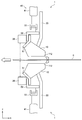
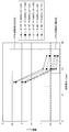
- FIG. 4 is a rear view of the liquid removal device shown in FIG. 3; It is an explanatory view showing the detailed composition of the slit nozzle concerning the embodiment. It is an explanatory view showing an example of one relation between flow velocity u + (x) and flow velocity u ⁇ (x) when the back length L is 20 mm and the sum of the injection angle ⁇ and the back inclination angle ⁇ is 90 °.
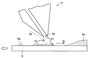
- FIG. 1 is an explanatory view showing a liquid removing condition by a liquid removing device using a general slit nozzle 3.
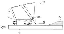
- FIG. 2 is an explanatory view showing a liquid removing condition by the liquid removing device using the slit nozzle 10 according to one embodiment of the present invention.
- liquid removing apparatus air is jetted to the surface of a steel plate which is a plate-like member by a slit nozzle to remove liquid on the surface of the steel plate.
- a liquid removing apparatus using a general slit nozzle as shown in FIG. 1, the jet of the slit nozzle 3 against the surface of the steel plate from the downstream side of the moving direction of the steel plate moving relative to the liquid removing apparatus
- An air blowing device for injecting air from the port 3a is used. As shown in FIG.
- the high-speed gas jet flow f1 injected from the slit nozzle 3 collides with the surface of the steel plate S, and pushes back the liquid 5a on the steel plate S by the flow f2 toward the upstream side in the moving direction. The liquid 5a on the steel plate S is removed.
- the inventor of the present application examined the configuration of a liquid removal apparatus capable of suppressing the decrease in the collision pressure of the gas jet f1 due to the interference between the outside air suction flow f4 and the reverse flow f3 after the surface collision of the steel plate S.
- the nozzle back surface 104 which is the surface on the downstream side of the moving direction of the steel plate S, extends along the surface of the steel plate S downstream in the moving direction than the slit nozzle 3 shown in FIG.
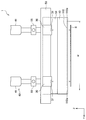
- FIG. 3 is a side view showing a configuration example of the liquid removing device 1 according to the present embodiment.
- FIG. 4 is a rear view of the liquid removing device 1 shown in FIG.
- the case where the liquid removing device 1 is used in a fixed manner will be described. That is, it is assumed that the slit nozzle 10 is fixed, and the steel plate S transported by the transport device moves relative to the slit nozzle 10.
- the liquid removing apparatus 1 is an apparatus for removing the liquid attached to the surface of a steel plate S which is an example of a plate-like member, for example.
- the liquid removal device 1 is fixed, and the steel plate S moves relative to the liquid removal device 1 by the steel plate S being transported by the transport device.
- the moving direction of the steel plate S moving relative to the liquid removing apparatus 1 is also referred to as a conveying direction.
- the liquid removing devices 1 are respectively disposed above and below so as to be symmetrical with respect to the steel plate S conveyed by the conveying device.
- the upper and lower liquid removing devices 1 may have the same configuration.
- the conveying apparatus which conveys the steel plate S may be, for example, a table roll which moves the placed steel plate S by rotation.
- the transport device may be a take-up and unwinding device including two end rolls provided at both ends of the liquid removing device 1 in the transport direction of the steel plate S.
- the take-up and unwinding device includes, as both end rolls, a pay-off reel for unwinding the steel sheet S wound in a coil and a tension reel for winding the steel sheet S from which the liquid on the surface has been removed by the liquid removing device 1 in a coil. Is equipped.
- the liquid removing device 1 includes a slit nozzle 10, a gap measuring device 30, and a gap adjusting mechanism 40, as shown in FIG.
- the slit nozzle 10 injects a gas (for example, air) fed from the outside through the air supply pipe 20 from the injection port 112 at the tip of the nozzle to the surface of the steel plate S.
- the slit nozzle 10 is disposed such that the slit length direction of the injection port 112 opening like a slit corresponds to the width direction of the steel plate S. Thereby, the liquid on the steel plate S can be removed over the entire width of the steel plate S.
- the injection port 112 is directed to the surface of the steel plate S so as to inject gas from the downstream side in the transport direction of the steel plate S toward the upstream side (that is, from the X-axis negative direction side toward the positive direction).
- a gas for example, air
- the slit nozzle 10 adjusts the gap to make the slit nozzle 10 approach / separate to the steel plate S on both sides in the slit length direction (Y direction) of the injection port 112 opened in a slit shape. It is supported by a mechanism 40. By moving the slit nozzle 10 up and down by the gap adjustment mechanism 40, the gap between the injection port 112 and the surface of the steel plate S can be adjusted.
- the slit nozzle 10 suppresses the influence of the external air suction flow f4 and suppresses the disturbance of the gas jet f1, so that the nozzle pressure which is the gas pressure inside the slit nozzle 10
- the injection angle of the slit nozzle 10, the back surface inclination angle, the back surface length, the slit width and the gap satisfy the predetermined relationship.
- the detailed configuration of the slit nozzle 10 and the relationship with the nozzle pressure will be described later.
- the gap measuring device 30 measures the distance between the injection port 112 at the tip of the slit nozzle 10 and the surface of the steel plate S (hereinafter also referred to as “gap”). As shown in FIGS. 3 and 4, the gap measuring devices 30 are respectively provided on both sides in the slit length direction (Y direction) of the injection port 112 of the slit nozzle 10. By providing the gap measuring device 30 at such a position, it is possible to detect the inclination of the jet nozzle 112 of the slit nozzle 10 with respect to the surface of the steel plate S in the slit length direction, so that the gap becomes constant in the slit length direction. Can be adjusted.
- the gap measuring device 30 may be provided, for example, at substantially the same position as the gap adjusting mechanism 40 that moves the slit nozzle 10 up and down in the slit length direction.
- the gap measuring device 30 includes a distance sensor 31 such as a laser distance meter.
- the gap measuring device 30 causes the distance sensor 31 to face the surface of the steel plate S, and based on the phase difference between the laser light emitted to the steel plate S and the reflected light of the laser light on the surface of the steel plate S, Measure
- one distance sensor 31 may be provided in each of the gap measuring devices 30 or a plurality of distance sensors 31 may be provided in the slit length direction.
- the distance sensor 31 is disposed near both ends 112 e of the injection port 112.
- the distance sensor 31 when the length of the injection port 112 of the slit nozzle 10 in the slit length direction is taken as the slit length w in the vicinity of both ends 112 e of the injection port 112, ⁇ 1/4 w from both ends 112 e of the injection port 112 I say the range.
- the distance sensor 31 since the distance sensor 31 needs to be opposed to the steel plate S, for example, the distance sensor 31 is installed according to the minimum plate width and the maximum plate width of the steel plate S which can be passed through the line on which the liquid removing device 10 is installed. The position is determined. As described above, the distance sensor 31 is disposed in the vicinity of both ends 112 e of the injection port 112 so as to face the steel plate S.
- the distance sensor 31 may be installed at a position about 1/6 of the plate width from the end of the steel plate S.
- the gap measuring device 30 outputs the gap obtained based on the detection result of the distance sensor 31 to the gap adjusting mechanism 40 as a gap measurement value.
- the gap adjusting mechanism 40 adjusts the gap to a predetermined size based on the measurement result of the gap measuring device 30.
- the gap adjustment mechanism 40 includes a drive unit 41 that moves the slit nozzle 10 up and down (Z direction), and a control unit (not shown) that controls the drive of the drive unit 41.
- the drive units 41 are provided on both sides in the slit length direction (Y direction) of the injection port 112 of the slit nozzle 10, and the slits are formed through the support members 51, 53, 55.
- the nozzle 10 is supported.
- the drive part 41 is comprised, for example with a cylinder, and can adjust the height position of the slit nozzle 10 by moving the piston to which the support member 55 was fixed.
- the drive part 41 may be an actuator which changes the height position of the table roll in which steel plate S was mounted, for example.
- the gap can also be adjusted by bringing the table roll close to / separating from the injection port 112 of the slit nozzle 10 in this manner.
- the control unit drives each drive unit 41 so as to approach the steel plate S as much as possible within the range in which the injection port 112 does not contact the steel plate S based on the measurement result of the gap measuring device 30, and adjusts the height position of the slit nozzle 10. Do. Since the gap measurement value by the gap measurement device 30 is the distance from the distance sensor to the surface of the steel plate S, the control unit subtracts the distance between the distance sensor and the injection port 112 of the slit nozzle 10 from the gap measurement value As the current gap, the height position of the slit nozzle 10 is adjusted to be within a predetermined range.
- the gas injected from the slit nozzle 10 flows between the nozzle back surface of the slit nozzle 10 and the steel plate S, and the outside air suction flow (f4) is a gas jet (f1) as shown in FIG. It is possible to suppress the influence of In order to exert such an effect, it is preferable to set the gap to 20 mm or less by the gap adjusting mechanism 40.
- the slit nozzle 10 suppresses the influence of the external air suction flow f4 to suppress the disturbance of the gas jet f1, the nozzle pressure of the slit nozzle 10, the injection angle of the slit nozzle 10, The back surface inclination angle, the back surface length, the slit width and the gap are configured to satisfy a predetermined relationship.
- FIG. 5 is an explanatory view showing a detailed configuration of the slit nozzle 10 according to the present embodiment.
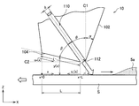
- the slit nozzle 10 includes a nozzle front surface 102 directed from the injection port 112 toward the transport direction upstream of the steel plate S, and a nozzle back surface 104 directed from the injection port 112 toward the transport direction downstream of the steel sheet S.
- the nozzle front surface 102 is restrained from being inclined to the upstream side in the transport direction, and the nozzle back surface 104 is extended to the downstream side in the transport direction along the surface of the steel plate S.
- the angle between the reference direction C1 and the injection direction C3 of the gas from the injection port 112 of the slit nozzle 10 is the injection angle ⁇ [°].
- the angle between the nozzle front surface 102 and the nozzle front surface 102 is referred to as a front surface inclination angle ⁇ [°]
- the angle between the gas injection direction C3 and the nozzle rear surface 104 is referred to as a back surface inclination angle ⁇ [°].
- the length of the nozzle back surface 104 in the conveyance direction C2 of the steel plate S be a back surface length L [mm].
- the liquid removing apparatus 1 is configured to satisfy the relationships of the following formulas (1) to (3).
- the injection angle ⁇ and the back surface inclination angle ⁇ represent magnitudes, and are represented by a value of 0 or more.
- the front inclination angle ⁇ the inclination of the steel plate S to the upstream side in the transport direction is represented as a positive value and the inclination to the downstream side is represented as a negative value, with the reference direction C1 being 0 °.
- the back surface length L is L ′ cos (90 ° ⁇ ), where the actual back surface length is L ′ [mm]. It can be calculated by - ⁇ ).
- the back length L corresponds to the length of the nozzle back surface 104 in the transport direction (X direction) on the horizontal projection plane when the nozzle back surface 104 is projected onto the horizontal projection plane.
- Equation (1) represents the conditions for suppressing the disturbance of the gas jet f1 by suppressing the influence of the outside air suction flow f4 shown in FIG. 1 and FIG.
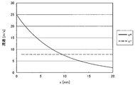
- u + (x) flow rate drawn into the injection port side at the Coanda effect u - (x): the transport direction of the gas jet impinging on the steel plate (X-direction) component velocity y (x): distance between steel sheet and the nozzle back ⁇ : Tube friction coefficient
- the transport direction component flow velocity u ⁇ (x) of the gas jet that has collided with the steel plate can be obtained by the following formula (1-4) using the flow velocity u of the jet of gas injected from the slit nozzle 10.
- the flow velocity u + (L) is the flow velocity u - (L) when less is (u + (L) ⁇ u - (L)) , that is, the transport direction component velocity u of gas jet - (L) is a Coanda This is when the flow velocity is higher than the flow velocity u + (L) drawn by the effect.
- the gas jet f1 is not affected by the flow velocity u + (L) drawn by the Coanda effect, and does not vibrate. Therefore, the gas jet f1 collides with the steel plate S without being disturbed, and as shown in FIG.
- An example of the relationship between the flow direction component flow velocity u ⁇ (x) of the gas jet that collides with the steel plate S is shown.
- the component flow direction u ⁇ (x) of the gas jet in the transport direction is smaller than the flow velocity u + (x) drawn toward the injection port 112 by the Coanda effect. Flow is turbulent and the gas jet f1 is disturbed.
- the inventor of the present application has examined the configuration and setting of the liquid removal apparatus 1 in which the component flow velocity u ⁇ (L) of the gas jet in the transport direction is equal to or higher than the flow velocity u + (L) drawn by the Coanda effect. I considered the relational expression of 1).
- the nozzle pressure P n [KPa] of the slit nozzle 10 is the gap h [mm], the back length L [mm], the back inclination angle ⁇ [°], the slit width d [mm], and the injection angle ⁇ [°]
- the slit nozzle 10 By configuring and arranging the slit nozzle 10 so as to be equal to or greater than the value of the relational expression F (h, L, ⁇ , ⁇ , d) represented by, the influence of the external air suction flow f4 is suppressed, and the gas jet f1 The disturbance can be suppressed.
- the relational expression F (h, L, ⁇ , ⁇ , d) visualizes the flow on the nozzle back surface 104 of the slit nozzle 10 by, for example, Tuft method, and specifies the nozzle pressure P n at which the flow on the nozzle back surface 104 rectifies.
- the slit width d is 0.4 mm
- the gap h is 1 mm to 25 mm
- the back length L is 10 to 50 mm
- the back inclination angle ⁇ is 5 to 45 °
- the injection angle ⁇ is 0 to 75 °
- the threshold value of the nozzle pressure P n at which the flow of the nozzle back surface 104 rectifies when the nozzle pressure P n is gradually changed from 5 to 1000 KPa is set using the Tuft method. It is.
- a polyethylene yarn having a diameter of 0.025 mm and a length of 3 mm is disposed at a pitch of 5 mm on the nozzle back surface 104 along the conveyance direction of the steel plate S, and changes according to the nozzle pressure P n
- the flow of the nozzle back surface 104 was visualized by moving the yarn by the flow of When all the yarns provided on the nozzle back surface 104 face the conveyance direction of the steel plate S, it is determined that the flow of the nozzle back surface 104 is rectified, and the nozzle pressure P n at this time is used as a threshold.
- the gap h, the back surface length L, the back surface inclination angle ⁇ , and the injection angle ⁇ are set as follows.
- the injection angle ⁇ and the back surface inclination angle ⁇ are set such that their sum is 60 ° or more, as expressed by the equation (2).
- the sum of the injection angle ⁇ and the back surface inclination angle ⁇ represents the inclined state of the nozzle back surface 104 with respect to the reference direction C1.
- the sum of the injection angle ⁇ and the back surface inclination angle ⁇ is 90 °, the nozzle back surface 104 and the surface of the steel plate S become parallel.
- the sum of the injection angle ⁇ and the back surface inclination angle ⁇ is set to 60 ° or more.
- the upper limit of the sum of the injection angle ⁇ and the back surface inclination angle ⁇ is a maximum value in a range in which the nozzle back surface 104 does not contact the surface of the steel plate S.
- the nozzle back surface 104 be disposed so as to be parallel to the surface of the steel plate S. That is, it is preferable that the sum of the injection angle ⁇ and the back surface inclination angle ⁇ be 90 °.
- the reverse flow f3 toward the downstream side of the conveyance direction of the steel plate S smoothly flows between the nozzle back surface 104 and the surface of the steel plate S. it can.
- the gas injection angle ⁇ be 45 °.
- the gas injected from the injection port 112 of the slit nozzle 10 collides at an angle of 45 ° from the downstream side in the transport direction with respect to the surface of the steel plate S, and the liquid 5a on the surface of the steel plate S is transported upstream It can be effectively pushed back to the side and removed.
- the sum of the injection angle ⁇ and the back surface inclination angle ⁇ be 90 °
- the injection angle ⁇ and the back surface inclination angle ⁇ should each be 45 °.
- the back surface length L of the nozzle back surface 104 is set to 20 mm or more, as shown in equation (3).
- the back length L is smaller than 20 mm, the outside air suction flow f4 and the reverse flow f3 collide in the vicinity of the gas jet f1, and the gas jet f1 is disturbed. Therefore, by setting the back length L to 20 mm or more, collision between the outside air suction flow f4 and the reverse flow f3 is prevented from occurring near the gas jet f1, and the disturbance of the gas jet f1 due to the outside air suction flow f4 is suppressed. .
- the back length L is preferably set to 20 mm or more.
- the upper limit of the back surface length L of the nozzle back surface 104 is not particularly limited, but in terms of equipment, it is sufficient if there is no contact with other members.
- the back length L may be up to about 100 mm.
- the gap h which is the distance between the injection port 112 and the surface of the steel plate S, is desirably set as close as possible to the steel sheet S within the range in which the injection port 112 does not contact the steel sheet S.
- the gap h it is desirable for the gap h to be, for example, 20 mm or less.
- the front inclination angle ⁇ is not particularly limited, but may be set to 30 ° or less.
- the front inclination angle ⁇ becomes larger than 30 °, the nozzle front surface 102 is inclined to the upstream side in the transport direction too much, and the gas jet f1 collides with the surface of the steel plate S, and then the flow f2 directed to the upstream side in the transport direction It is likely to flow toward the injection port 112 of the slit nozzle 10 again along the nozzle front surface 102 without going to the front.
- the removal performance of the liquid 5a on the surface of the steel plate S by the flow f2 is reduced.
- the front inclination angle ⁇ may be set to 30 ° or less in order to suppress the decrease in the liquid removal performance.
- the front side inclination angle ⁇ is 0 ° or less.
- the slit nozzle 10 is configured and arranged so as to satisfy the expressions (1) to (3).
- the pressure of the upstream flow f2 can also be maintained. Therefore, the liquid 5a on the steel plate S can be sufficiently removed.
- the liquid removing apparatus 1 since the liquid on the steel plate can be sufficiently removed without using a ringer roll or a dryer, the cost for maintaining the equipment can also be reduced.
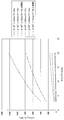
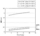
- FIG. 8 shows the relationship between the gap h and the nozzle pressure P n calculated by the above equation (1) when the back surface inclination angle ⁇ and the back surface length L are changed with the injection angle ⁇ being 45 °.
- the nozzle pressure P n shown in FIG. 8 indicates a threshold value when it is determined that the flow of the nozzle back surface 104 is rectified by the above-mentioned Tuft method, and when both sides of the equation (1) show the same value
- the value of P n F (h, L, ⁇ , ⁇ , d)). That is, the plot lines of cases a to f shown in FIG. 8 indicate the boundary between the area where the flow of the nozzle back surface 104 is rectified and the area where the flow is turbulent.
- the nozzle pressure P n becomes equal to or greater than the value of the relational expression F (h, L, ⁇ , ⁇ , d), and the relationship of the above equation (1) is obtained.
- the flow of the nozzle back surface 104 is in a rectified state.
- the nozzle pressure P n is smaller than the value of the relational expression F (h, L, ⁇ , ⁇ , d), and the relationship of the above expression (1) is not satisfied.
- the flow of the nozzle back surface 104 becomes turbulent, and the gas jet f1 is disturbed.
- the sum of the back surface inclination angle ⁇ and the injection angle ⁇ is 90 ° in the cases a to c and 60 ° in the cases d to f, and both satisfy the above equation (2).
- the cases a, b, d and e are 25 mm or 20 mm and satisfy the above equation (3), but the cases c and f are 15 mm and do not satisfy the equation (3).
- the plot lines of cases c and f not satisfying the above equation (3) are inclined in comparison with the plot lines of cases a, b, d and e satisfying the above equation (3) Even when the gap h approaches 3 mm, the nozzle pressure P n needs to be 200 KPa or more.
- a nozzle pressure P n of 200 KPa or more is required, the pressure can not be secured depending on the piping installation situation in the factory, and the liquid removal device 1 can not be installed, or even if the liquid removal device 1 can be installed It is expected to become enormous and cost increase. Therefore, it is preferable to set the back length L to 20 mm or more.
- the plot lines of cases a, b, d, and e have similar gradients, and even if the gap h becomes large or the nozzle pressure P n of the slit nozzle 10 is set smaller than 200 KPa, It is possible to satisfy the equation (1).
- the back surface length L is the same, the required nozzle pressure P n can be reduced as the sum of the back surface inclination angle ⁇ and the injection angle ⁇ is larger.
- the slit nozzle 10 is configured and arranged to satisfy the above equations (1) to (3) to rectify the flow of the nozzle back surface 104 so that the flow of the gas jet f1 is not affected. can do.
- the versatility of the air pressure can be secured, and it is possible to realize a liquid removal apparatus in which the air flow rate is also economical.
- the slit nozzle 10 of the liquid removing apparatus 1 shown in FIG. 5 shows the case where the outer shape of the nozzle itself is formed so as to satisfy the above equations (1) to (3), but the present invention is limited to such an example I will not.
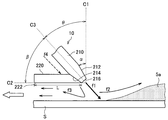
- the slit nozzle 10 of the liquid removal apparatus 1 is a slit nozzle (hereinafter referred to as a "nozzle main body") 210 having a generally used axially symmetrical outer shape, and a back member 220 may be comprised.
- the nozzle body 210 has an injection port 216 which is a slit for injecting a gas.
- the nozzle body front surface 212 and the nozzle body rear surface 214 are symmetrical with respect to the gas injection direction C3.
- the back member 220 is, for example, a plate material such as a steel plate.
- the back member 220 is connected to the nozzle body back surface 214, and constitutes a nozzle back surface extending from the injection port 216 of the nozzle body 210 toward the downstream side in the conveyance direction of the steel plate S. That is, the opposite surface of the back member 220 facing the surface of the steel plate S is the nozzle back surface.
- the bottom surface 222 of the back member 220 functioning as the nozzle back surface extends along the surface of the steel plate S along the surface of the steel sheet S so as to satisfy the above equations (1) to (3).
- the collision of the gas jet f1 due to the collision between the external air suction flow f4 and the reverse flow f3 can be reduced, and the gas jet f1 collides with the surface of the steel plate S. Since the collision pressure at that time does not decrease and the pressure of the flow f2 directed to the upstream side in the transport direction can also be maintained, the liquid 5a on the steel plate S can be sufficiently removed.
- the configuration as shown in FIG. 10 can be realized by providing the back member 220 with respect to the nozzle main body 210 which is an existing slit nozzle, and the change with respect to the existing equipment can be reduced.
- the effect of removing the liquid on the surface of the steel sheet S can be sufficiently obtained also by the liquid removing device having such a configuration.
- Liquid removal method The removal of the liquid adhering to the surface of the steel plate S is performed by causing the slit nozzle 10 of the liquid removal apparatus 1 described above to face the surface of the steel plate S and injecting gas from the slit nozzle 10 to the surface of the steel plate S.
- the gap between the injection port 112 of the slit nozzle 10 and the steel plate S is measured by the gap measuring device 30.
- the gap is adjusted to 20 mm or less by driving and changing the position of at least one of the slit nozzle 10 or the steel plate S by the drive unit of the gap adjusting mechanism 40 based on the measured gap.
- the liquid adhering to the surface of the steel plate S can be removed by injecting gas with respect to the surface of the steel plate S from the slit nozzle 10, moving the slit nozzle 10 and the steel plate S relatively.
- the measurement of the gap by the gap measuring device 30 and the gap adjustment by the gap adjusting mechanism 40 may be performed each time the steel sheet S to be treated is different.
- the gap may be measured by the gap measuring device 30 in real time during the passage of the steel plate S, and the gap may be adjusted to 20 mm or less by the gap adjusting mechanism 40 based on the acquired gap measurement value.
- the liquid removing effect of removing the liquid on the surface of the steel plate was verified.
- the liquid removal device according to the present invention was installed after the cleaning equipment of the continuous steel plate processing line, and the film thickness of the liquid remaining on the steel plate surface was measured after removing the liquid on the steel plate surface by the liquid removal device. . Ringer roll and dryer were not used.
- the line speed of the steel plate was 100 mpm
- the gap was 3 mm
- the injection angle ⁇ was 45 °
- the slit width d was 0.4 mm.
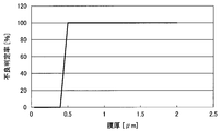
- the liquid removing effect was evaluated by the film thickness of the liquid remaining after removing the liquid on the steel plate surface by the liquid removing device.
- the evaluation of drainage is done visually.
- the film thickness of the liquid on the surface of the steel plate is 0.5 ⁇ m or more, the remaining liquid is visually confirmed, so it is determined that the quality of the surface of the steel plate is poor. From this, when the film thickness of the liquid on the steel plate surface was smaller than 0.5 ⁇ m, it was evaluated that there was a liquid removal effect.
- the sum of the injection angle ⁇ and the back surface inclination angle ⁇ is 60 ° or more, and the slit nozzle is configured to satisfy the above equation (2).
- the film thickness of the liquid on the steel plate surface is 0.5 ⁇ m or more And a sufficient draining effect could not be obtained.
- the nozzle pressure P n is set high when the injection angle ⁇ , the front inclination angle ⁇ , the rear inclination angle ⁇ , the slit width d, and the back length L of the nozzle back are the same through the cases A to F. It can be seen that the more effective the drainage effect is.
- the back surface inclination angle ⁇ is 45 °
- the liquid removing device 1 including the slit nozzle 10 is fixed, and the steel plate S is conveyed by the conveying device and is moved relative to the slit nozzle 10. It is not limited to such an example.
- the liquid removing apparatus according to the present invention is applicable even when the plate-like member is stationary and the liquid removing device provided with the slit nozzle is moved relative to the plate-like member in parallel by the nozzle moving mechanism. .
Landscapes
- Chemical & Material Sciences (AREA)
- Chemical Kinetics & Catalysis (AREA)
- General Chemical & Material Sciences (AREA)
- Engineering & Computer Science (AREA)
- Materials Engineering (AREA)
- Mechanical Engineering (AREA)
- Metallurgy (AREA)
- Organic Chemistry (AREA)
- Cleaning In General (AREA)
- Cleaning And De-Greasing Of Metallic Materials By Chemical Methods (AREA)
- Cleaning By Liquid Or Steam (AREA)
- Nozzles (AREA)
Abstract
Priority Applications (8)
| Application Number | Priority Date | Filing Date | Title |
|---|---|---|---|
| ES17775248T ES2883149T3 (es) | 2016-03-29 | 2017-03-29 | Aparato para retirar líquido y método para retirar líquido |
| BR112018013095-8A BR112018013095B1 (pt) | 2016-03-29 | 2017-03-29 | Método para remoção de líquidos |
| KR1020187023431A KR102223513B1 (ko) | 2016-03-29 | 2017-03-29 | 액체 제거 장치 및 액체 제거 방법 |
| US16/067,371 US11174558B2 (en) | 2016-03-29 | 2017-03-29 | Liquid removal device and liquid removal method |
| CA3009318A CA3009318C (fr) | 2016-03-29 | 2017-03-29 | Appareil d'elimination de liquide et procede d'elimination de liquide |
| EP17775248.2A EP3444381B1 (fr) | 2016-03-29 | 2017-03-29 | Appareil d'élimination de liquide et procédé d'élimination de liquide |
| CN201780013254.9A CN108699707B (zh) | 2016-03-29 | 2017-03-29 | 液体去除装置和液体去除方法 |
| JP2018509349A JP6402839B2 (ja) | 2016-03-29 | 2017-03-29 | 液体除去装置及び液体除去方法 |
Applications Claiming Priority (2)
| Application Number | Priority Date | Filing Date | Title |
|---|---|---|---|
| JP2016-066122 | 2016-03-29 | ||
| JP2016066122 | 2016-03-29 |
Publications (1)
| Publication Number | Publication Date |
|---|---|
| WO2017170714A1 true WO2017170714A1 (fr) | 2017-10-05 |
Family
ID=59964612
Family Applications (1)
| Application Number | Title | Priority Date | Filing Date |
|---|---|---|---|
| PCT/JP2017/012951 Ceased WO2017170714A1 (fr) | 2016-03-29 | 2017-03-29 | Appareil d'élimination de liquide et procédé d'élimination de liquide |
Country Status (9)
| Country | Link |
|---|---|
| US (1) | US11174558B2 (fr) |
| EP (1) | EP3444381B1 (fr) |
| JP (1) | JP6402839B2 (fr) |
| KR (1) | KR102223513B1 (fr) |
| CN (1) | CN108699707B (fr) |
| BR (1) | BR112018013095B1 (fr) |
| CA (1) | CA3009318C (fr) |
| ES (1) | ES2883149T3 (fr) |
| WO (1) | WO2017170714A1 (fr) |
Families Citing this family (4)
| Publication number | Priority date | Publication date | Assignee | Title |
|---|---|---|---|---|
| WO2017213021A1 (fr) * | 2016-06-09 | 2017-12-14 | Jfeスチール株式会社 | Procédé de production d'une tôle d'acier galvanisée et dispositif de production associé |
| BE1025125B1 (fr) * | 2017-09-04 | 2018-10-31 | Centre de Recherches Métallurgiques asbl-Centrum voor Research in de Metallurgie vzw | Essuyeur sans contact et installation industrielle comportant un tel essuyeur |
| CN111940414A (zh) * | 2020-08-31 | 2020-11-17 | 合肥市商巨智能装备有限公司 | 干式超声波清洗装置及清洗方法 |
| CN119114655A (zh) * | 2024-10-21 | 2024-12-13 | 中冶南方工程技术有限公司 | 板带表面残留液清除装置及方法 |
Citations (4)
| Publication number | Priority date | Publication date | Assignee | Title |
|---|---|---|---|---|
| JPS5612316B2 (fr) * | 1976-08-19 | 1981-03-19 | ||
| JPH06336667A (ja) * | 1993-05-31 | 1994-12-06 | Kawasaki Steel Corp | 溶融めっきの付着量制御方法 |
| JPH10211514A (ja) * | 1997-01-29 | 1998-08-11 | Nippon Steel Corp | ルーパー機能を有するブライドル装置及びその使用方法 |
| WO2012172648A1 (fr) * | 2011-06-14 | 2012-12-20 | 三菱日立製鉄機械株式会社 | Équipement de placage par immersion à chaud en continu |
Family Cites Families (20)
| Publication number | Priority date | Publication date | Assignee | Title |
|---|---|---|---|---|
| US3747481A (en) * | 1970-12-16 | 1973-07-24 | Inter Paper Co | Apparatus and method for handling large size corrugated paperboard panels |
| JPS5612316A (en) | 1979-07-09 | 1981-02-06 | Kureha Chem Ind Co Ltd | Remedy for peptic ulcer, containing morpholine derivative |
| US5014447A (en) * | 1988-02-10 | 1991-05-14 | Thermo Electron Web Systems, Inc. | Positive pressure web floater dryer with parallel flow |
| US5070628A (en) * | 1990-01-16 | 1991-12-10 | W. R. Grace & Co.-Conn. | Rotatable slot nozzle air bar |
| DE59202907D1 (de) | 1991-05-17 | 1995-08-24 | Sundwiger Eisen Maschinen | Vorrichtung zum Entfernen von Flüssigkeit von der Oberfläche eines bewegten Bandes. |
| JP3048763B2 (ja) | 1992-08-19 | 2000-06-05 | 新日本製鐵株式会社 | 鋼帯に付着する液体の除去方法 |
| JP3395696B2 (ja) | 1999-03-15 | 2003-04-14 | 日本電気株式会社 | ウェハ処理装置およびウェハ処理方法 |
| JP2002294478A (ja) | 2001-03-29 | 2002-10-09 | Mitsubishi Heavy Ind Ltd | 鋼帯の水切装置 |
| US6564473B2 (en) * | 2001-10-22 | 2003-05-20 | The Procter & Gamble Company | High efficiency heat transfer using asymmetric impinging jet |
| KR100641026B1 (ko) * | 2002-12-03 | 2006-11-02 | 주식회사 케이씨텍 | 슬릿형 노즐을 가지는 혼합 유체 분사 기구 |
| JP4352047B2 (ja) * | 2003-03-04 | 2009-10-28 | 三菱レイヨン株式会社 | シート状物の熱処理装置および熱処理方法 |
| JP2006122784A (ja) * | 2004-10-27 | 2006-05-18 | Sharp Corp | 基板洗浄方法および基板洗浄装置 |
| JP4720198B2 (ja) * | 2005-02-03 | 2011-07-13 | Jfeスチール株式会社 | 厚鋼板の冷却装置および冷却方法 |
| JP4330565B2 (ja) * | 2005-08-10 | 2009-09-16 | シャープ株式会社 | 基板洗浄ノズルおよび基板洗浄装置 |
| KR100758220B1 (ko) * | 2005-10-20 | 2007-09-17 | 주식회사 케이씨텍 | 다중 슬릿형 노즐을 가지는 기판 세정 장치 및 이를 이용한세정 방법 |
| JP4609392B2 (ja) | 2006-07-21 | 2011-01-12 | 住友金属工業株式会社 | 金属板材に付着した液体の除去方法及び除去装置 |
| US7697126B2 (en) * | 2008-04-02 | 2010-04-13 | Spatial Integrated Systems, Inc. | Three dimensional spatial imaging system and method |
| JP2013181196A (ja) * | 2012-03-01 | 2013-09-12 | Jfe Steel Corp | 目詰まり除去治具を備えるワイピングノズル |
| JP6205753B2 (ja) | 2013-02-28 | 2017-10-04 | 新日鐵住金株式会社 | ガスワイピングノズル及びガスワイピング方法 |
| JP6367763B2 (ja) * | 2015-06-22 | 2018-08-01 | 株式会社荏原製作所 | ウェーハ乾燥装置およびウェーハ乾燥方法 |
-
2017
- 2017-03-29 WO PCT/JP2017/012951 patent/WO2017170714A1/fr not_active Ceased
- 2017-03-29 CN CN201780013254.9A patent/CN108699707B/zh active Active
- 2017-03-29 US US16/067,371 patent/US11174558B2/en active Active
- 2017-03-29 EP EP17775248.2A patent/EP3444381B1/fr active Active
- 2017-03-29 ES ES17775248T patent/ES2883149T3/es active Active
- 2017-03-29 JP JP2018509349A patent/JP6402839B2/ja active Active
- 2017-03-29 KR KR1020187023431A patent/KR102223513B1/ko active Active
- 2017-03-29 BR BR112018013095-8A patent/BR112018013095B1/pt active IP Right Grant
- 2017-03-29 CA CA3009318A patent/CA3009318C/fr active Active
Patent Citations (4)
| Publication number | Priority date | Publication date | Assignee | Title |
|---|---|---|---|---|
| JPS5612316B2 (fr) * | 1976-08-19 | 1981-03-19 | ||
| JPH06336667A (ja) * | 1993-05-31 | 1994-12-06 | Kawasaki Steel Corp | 溶融めっきの付着量制御方法 |
| JPH10211514A (ja) * | 1997-01-29 | 1998-08-11 | Nippon Steel Corp | ルーパー機能を有するブライドル装置及びその使用方法 |
| WO2012172648A1 (fr) * | 2011-06-14 | 2012-12-20 | 三菱日立製鉄機械株式会社 | Équipement de placage par immersion à chaud en continu |
Non-Patent Citations (1)
| Title |
|---|
| See also references of EP3444381A4 * |
Also Published As
| Publication number | Publication date |
|---|---|
| JP6402839B2 (ja) | 2018-10-10 |
| BR112018013095A2 (pt) | 2018-12-11 |
| CA3009318A1 (fr) | 2017-10-05 |
| EP3444381B1 (fr) | 2021-07-21 |
| EP3444381A1 (fr) | 2019-02-20 |
| KR102223513B1 (ko) | 2021-03-05 |
| CA3009318C (fr) | 2020-06-30 |
| CN108699707B (zh) | 2020-03-17 |
| KR20180102160A (ko) | 2018-09-14 |
| CN108699707A (zh) | 2018-10-23 |
| EP3444381A4 (fr) | 2019-12-25 |
| BR112018013095B1 (pt) | 2023-04-18 |
| ES2883149T3 (es) | 2021-12-07 |
| US11174558B2 (en) | 2021-11-16 |
| US20180327914A1 (en) | 2018-11-15 |
| JPWO2017170714A1 (ja) | 2018-08-30 |
Similar Documents
| Publication | Publication Date | Title |
|---|---|---|
| WO2017170714A1 (fr) | Appareil d'élimination de liquide et procédé d'élimination de liquide | |
| US7943200B2 (en) | Method of curtain coating | |
| US7080465B2 (en) | Method of manufacturing inkjet recording sheet and drying apparatus for application film | |
| RU2615392C2 (ru) | Система для уменьшения потребления отжимающего газа в воздушном ноже | |
| JP5509648B2 (ja) | 熱延鋼板の通板時水切り方法および装置 | |
| US3469275A (en) | Apparatus for the contactless removing of dust from webs | |
| JP5565368B2 (ja) | ワイピング装置およびこれを用いた溶融めっき装置 | |
| JP2012051013A (ja) | 熱鋼板の水切り装置および水切り方法 | |
| CN101516753A (zh) | 卷状物输送装置及输送方法 | |
| JP7069708B2 (ja) | 水切り装置、水切り方法およびウェブの製造方法 | |
| BR112014004234B1 (pt) | dispositivo de enxugar uma folha de aço e aparelho de revestimento por imersão a quente | |
| JP7715110B2 (ja) | 金属板の通板時水切り装置および金属板の通板時水切り方法 | |
| JP7715111B2 (ja) | 金属板の通板時水切り装置、熱間圧延設備および熱間圧延鋼帯の製造方法 | |
| JP5239852B2 (ja) | 熱延鋼帯の製造方法 | |
| JP5760709B2 (ja) | 鋼帯の水切り装置 | |
| JP2020083625A (ja) | 非接触式搬送装置における帯状基材の蛇行制御方法 | |
| JP3632560B2 (ja) | ホットランテーブルにおける熱延鋼帯の搬送方法 | |
| JP2001246412A (ja) | 熱延鋼帯の冷却装置と、その冷却方法 | |
| JP2000225410A (ja) | 熱間圧延におけるストリップ搬送方法および装置 | |
| JP4987672B2 (ja) | ガスワイピング装置 | |
| KR20030016433A (ko) | 표면 청정도가 우수한 열간압연강판의 제조방법 | |
| JP5347781B2 (ja) | 熱鋼板の冷却設備および冷却方法 | |
| JP2004001032A (ja) | 熱延鋼帯後端部の通板方法 |
Legal Events
| Date | Code | Title | Description |
|---|---|---|---|
| ENP | Entry into the national phase |
Ref document number: 2018509349 Country of ref document: JP Kind code of ref document: A |
|
| ENP | Entry into the national phase |
Ref document number: 3009318 Country of ref document: CA |
|
| WWE | Wipo information: entry into national phase |
Ref document number: 16067371 Country of ref document: US |
|
| REG | Reference to national code |
Ref country code: BR Ref legal event code: B01A Ref document number: 112018013095 Country of ref document: BR |
|
| ENP | Entry into the national phase |
Ref document number: 20187023431 Country of ref document: KR Kind code of ref document: A |
|
| WWE | Wipo information: entry into national phase |
Ref document number: 1020187023431 Country of ref document: KR |
|
| WWE | Wipo information: entry into national phase |
Ref document number: 2017775248 Country of ref document: EP |
|
| NENP | Non-entry into the national phase |
Ref country code: DE |
|
| ENP | Entry into the national phase |
Ref document number: 2017775248 Country of ref document: EP Effective date: 20180928 |
|
| 121 | Ep: the epo has been informed by wipo that ep was designated in this application |
Ref document number: 17775248 Country of ref document: EP Kind code of ref document: A1 |
|
| ENP | Entry into the national phase |
Ref document number: 112018013095 Country of ref document: BR Kind code of ref document: A2 Effective date: 20180626 |