EP0438409B1 - Wasserkopfkissen - Google Patents
Wasserkopfkissen Download PDFInfo
- Publication number
- EP0438409B1 EP0438409B1 EP89905921A EP89905921A EP0438409B1 EP 0438409 B1 EP0438409 B1 EP 0438409B1 EP 89905921 A EP89905921 A EP 89905921A EP 89905921 A EP89905921 A EP 89905921A EP 0438409 B1 EP0438409 B1 EP 0438409B1
- Authority
- EP
- European Patent Office
- Prior art keywords
- pillow
- envelope
- liquid
- casing
- thin
- Prior art date
- Legal status (The legal status is an assumption and is not a legal conclusion. Google has not performed a legal analysis and makes no representation as to the accuracy of the status listed.)
- Expired - Lifetime
Links
Images



Classifications
-
- A—HUMAN NECESSITIES
- A47—FURNITURE; DOMESTIC ARTICLES OR APPLIANCES; COFFEE MILLS; SPICE MILLS; SUCTION CLEANERS IN GENERAL
- A47G—HOUSEHOLD OR TABLE EQUIPMENT
- A47G9/00—Bed-covers; Counterpanes; Travelling rugs; Sleeping rugs; Sleeping bags; Pillows
-
- A—HUMAN NECESSITIES
- A47—FURNITURE; DOMESTIC ARTICLES OR APPLIANCES; COFFEE MILLS; SPICE MILLS; SUCTION CLEANERS IN GENERAL
- A47C—CHAIRS; SOFAS; BEDS
- A47C27/00—Spring, stuffed or fluid mattresses or cushions specially adapted for chairs, beds or sofas
- A47C27/08—Fluid mattresses
- A47C27/088—Fluid mattresses incorporating elastic bodies, e.g. foam
-
- A—HUMAN NECESSITIES
- A47—FURNITURE; DOMESTIC ARTICLES OR APPLIANCES; COFFEE MILLS; SPICE MILLS; SUCTION CLEANERS IN GENERAL
- A47C—CHAIRS; SOFAS; BEDS
- A47C27/00—Spring, stuffed or fluid mattresses or cushions specially adapted for chairs, beds or sofas
- A47C27/08—Fluid mattresses
- A47C27/081—Fluid mattresses of pneumatic type
-
- A—HUMAN NECESSITIES
- A47—FURNITURE; DOMESTIC ARTICLES OR APPLIANCES; COFFEE MILLS; SPICE MILLS; SUCTION CLEANERS IN GENERAL
- A47C—CHAIRS; SOFAS; BEDS
- A47C27/00—Spring, stuffed or fluid mattresses or cushions specially adapted for chairs, beds or sofas
- A47C27/08—Fluid mattresses
- A47C27/085—Fluid mattresses of liquid type, e.g. filled with water or gel
-
- A—HUMAN NECESSITIES
- A47—FURNITURE; DOMESTIC ARTICLES OR APPLIANCES; COFFEE MILLS; SPICE MILLS; SUCTION CLEANERS IN GENERAL
- A47C—CHAIRS; SOFAS; BEDS
- A47C27/00—Spring, stuffed or fluid mattresses or cushions specially adapted for chairs, beds or sofas
- A47C27/14—Spring, stuffed or fluid mattresses or cushions specially adapted for chairs, beds or sofas with foamed material inlays
- A47C27/18—Spring, stuffed or fluid mattresses or cushions specially adapted for chairs, beds or sofas with foamed material inlays in combination with inflatable bodies
-
- A—HUMAN NECESSITIES
- A47—FURNITURE; DOMESTIC ARTICLES OR APPLIANCES; COFFEE MILLS; SPICE MILLS; SUCTION CLEANERS IN GENERAL
- A47G—HOUSEHOLD OR TABLE EQUIPMENT
- A47G9/00—Bed-covers; Counterpanes; Travelling rugs; Sleeping rugs; Sleeping bags; Pillows
- A47G9/10—Pillows
- A47G9/1081—Pillows comprising a neck support, e.g. a neck roll
-
- A—HUMAN NECESSITIES
- A47—FURNITURE; DOMESTIC ARTICLES OR APPLIANCES; COFFEE MILLS; SPICE MILLS; SUCTION CLEANERS IN GENERAL
- A47G—HOUSEHOLD OR TABLE EQUIPMENT
- A47G9/00—Bed-covers; Counterpanes; Travelling rugs; Sleeping rugs; Sleeping bags; Pillows
- A47G2009/008—Bed-covers; Counterpanes; Travelling rugs; Sleeping rugs; Sleeping bags; Pillows using a liquid as filling material
Definitions
- the present invention relates to water filled pillows, seat cushions and other cushions normally used in a horizontal orientation.
- the invention relates to pillows or cushions having a water envelope preferably for use on a flat surface such as a bed, cot or the like.
- an envelope layer is positioned adjacent the bottom surface thereof separated from the top surface by a compressible filler material.
- the invention is also related to improvements in pillows.
- United States Patent 3,298,044 in accordance with the preamble of claim 14 discloses an inflated pillow with centrally disposed bladders. A foam rubber sheath is applied about the bladders. The pillow is inflated with air for use and is deflated for storage. The structure of the pillow is symmetrical and there is no distinction between the top and bottom surface.
- a pillow casing for receiving a conventional headrest pillow having a compressible filler and for receiving a displaceable liquid or liquid-like layer
- the pillow casing comprising a fabric first surface and a connected fabric second surface, which cooperate to define a flexible enclosure for receiving the conventional pillow therein, and a thin deformable envelope for receiving a liquid or liquid-like material intermediate the said surfaces
- the said thin envelope is attached essentially immediately above and substantially completely covers said second surface and is adapted to receive and sealably retain a liquid or liquid-like material therein to form the thin displaceable liquid or liquid-like layer remote and isolated from the said first surface when the conventional pillow is received in the said enclosure, the conventional pillow when received in the said enclosure being supported by the said envelope to effectively float such received conventional pillow on such liquid or liquid-like layer received in the said envelope, the said liquid or liquid-like material being displaced in response to varying pressures exerted along the said envelope.
- a pillow comprising an outer casing defining readily deformable top and bottom surfaces and an envelope within the said casing, the said thin envelope being secured within the said casing to substantially completely overlie the said bottom surface and located below a central plane passing between the said top and bottom surfaces, characterised in that the said casing is of fabric; in that a compressible filler material is provided within and substantially fills the said casing; and in that the said envelope is thin and retains a thin layer of a fluid or fluid-like medium positioned below the compressible filler material and provides a bottom support surface for the said compressible filler material.
- the pillow 2 shown in the drawings has a casing 3 having a top surface 4, a bottom surface 6, a front surface 8 and a back surface 10.
- a compressible filler material 12 is shown and serves to separate the thin envelope 14 adapted to retain a fluid from the top surface 4.
- the compressible filler may be any suitable material such as chipped foam, solid foam, feathers, loose fiberfill or the like, which provide resiliency and comfort in supporting the head of a user.
- a pillow casing 9 about the pillow is a pillow casing 9.
- the envelope 14 is offset and below a center plane running horizontally through the pillow and in this preferred embodiment is separated from the bottom surface 6 of the pillow 2 by a foam wedge member 16 which predisposes the envelope 14 to slope from front to back and, in effect, raises the front portion of the envelope.
- a foam wedge member 16 which predisposes the envelope 14 to slope from front to back and, in effect, raises the front portion of the envelope.
- the wedge also serves to reduce the effect of displacement of the bed mattress on envelope 14 due to the weight of the user supported adjacent the pillow.
- the wedge member 16 is preferably of a maximum thickness of about 1.27 cm (1/2 inch).
- the water within the envelope remote the portion directly supporting the head of the user is not at a substantially elevated position where it would create a pressure due to the weight of the water. This pressure would tend to raise the head of the user and result in increased water movement with head movement and possible head discomfort.
- thermal reflector 18 Separating the thin envelope 14 from the bottom surface 6 is a thermal reflector 18. This thermal reflector 18 reduces heat transfer between bottom surface 6 and the envelope 14. Thus, if a user places their arm beneath the pillow, the amount of heat transfer between the arm and the envelope 14 is reduced.
- Compressible filler 12 reduces heat transfer between the head of the user and the envelope 14.
- the compressible filler is about 8.89 cm to 10.16 cm (3-1/2 to 4 inches) thick.
- a reclosable inlet 20 is provided through which a fluid can be introduced to the envelope.
- the inlet 20 is provided adjacent the bottom surface, making access convenient and isolating the inlet from any position which would render the pillow less usable.
- the position of the envelope, adjacent the bottom surface allows the spout of the inlet to be much shallower and thus reduces the effect of the same on the envelope.
- the envelope, itself, has opposed film 22 of ethylene vinyl acetate or the like heat sealed adjacent the perimeter.
- a flange area 24 is provided beyond the heat seal which serves as a means by which the envelope can be attached to he thermal reflector 18 and any other components. This is illustrated in the drawing by stitches 26 shown securing the sheets to the thermal reflector.
- the casing 3 in effect, provides sheets defining the top surface, bottom surface, front surface and back surface and, interior thereto, the thin envelope 14 and thermal reflector sheet 18.
- the compressible filler 12 can be inserted.
- the wedge member is added at the time the casing is stitched.
- a partition 11 has been provided which defines a pocket 15 at the front of the pillow which serves to retain filler in this location.
- the material of the envelope is preferably an ethylene vinyl acetate having about 12% vinyl acetate. This material is quite pliable and noiseless with deformation of the pillow.
- the envelope 14 does not extend to the perimeter of the pillow, thus further reducing the quantity of water.
- the envelope is about 50.8 cm (20 inches) by 33.02 cm (13 inches) with a securement edge thereabout.
- the orientation of the thin envelope 14 is determined and it will be generally supported along a flat planar type surface of a bed, cot or sofa. This location of the envelope renders it less susceptible to extreme deformations possible if the envelope was generally centrally disposed.
- the thickness of the envelope can be reduced whereby the characteristics of a water filled envelope are imparted to the pillow without a significant amount of water.
- the pillow is much more consistent as the orientation is assured and additional features, such as predisposing the envelope at an upward angle and having a greater thickness of filler material above the envelope, are practical as the range of deformation is reduced.
- the user will add the fluid to the thin envelope 14 and can vary the fill quantity if desired to achieve different characteristics.
- the inlet 20 to the envelope 14 is provided on the bottom surface and is accessible through the pillow. This is a reclosable inlet and, thus, the pillow may be adjusted as required by the user.
- the fill material can vary, however, it should be acceptable for the intended purpose of the pillow. Water is certainly adequate, although some gel type materials may also be useful.
- the envelope 14 does not require any baffling arrangement, as the size of the envelope is reduced and the displacement of water has been accommodated. This simplifies manufacture and consistency of the pillow.
- the envelope 14 shown need not extend to the perimeter of the pillow and a border area of 5.08 cm to 7.64 cm (2 to 3 inches) has proven acceptable. This reduced envelope size again reduces the fill quantity and weight of the pillow while still providing the improved characteristics. This probably occurs as the head of a user is supported over a fairly large area of the pillow and, thus, the envelope will be deformed and effect the compression of the pillow even if the user's head is positioned and supported at the pillow edge.
- the pillow casing 3, prior to being stuffed, is preferably about 50.8 cm by 66.04 cm (20 by 26 inches) and the envelope is centrally disposed and of a size of about 33.02 cm by 50.8 cm (13 by 20 inches).
- the fill quantity of the envelope can vary according to the user's requirements, however, it is preferably about 2266 cc (80 fluid ounces).
- the thickness of film 22 are preferably about .76 mm to 1.27 mm (3 to 5 mils).
- this pillow accommodates shifting in the head position to provide full support along the entire surface of the head in contact with the pillow and obviously will provide more uniform support than a conventional pillow.
- the movement of the pillow provides a massaging effect; a feature not found in conventional pillows.
- the positioning of the envelope is important to the present invention, as a position, for example, in the center line of the pillow does not achieve the advantages.
- the presence of the foam wedge member accommodates depression and orientation of the envelope for its intended use.
- the portion of the envelope beyond the head essentially acts as a reservoir and accommodates changing placements of the head on the pillow.
- the thermal reflector 18 is only required at the bottom of the envelope as the fill material above envelope 14 inherently acts as a good insulator.
- This thermal reflector can be wrapped about the envelope if desired to further insulate the top surface of the pillow from the envelope. The reflector is best separated from the top surface by the compressible filler material.
- this particular placement of the envelope 14 simplifies manufacture of the pillow as the envelope can be directly secured to the casing and the thermal reflector. This securement also limits the configuration of the envelope as it is mechanically fastened to the casing.
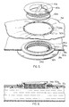
- the water pillow casing 2a of Figure 3 includes a top or first surface 4a and a bottom or second surface 6a which cooperate and collectively define a pillow slip type arrangment for receiving a conventional pillow or other suitable compressible fill material.
- a thin plastic fluid retaining envelope 8a which is attached by means of the fastening periphery 9a to the bottom surface 6a via the stitches 10a which pierce through the fastening periphery and pierce through the bottom surface 6a.
- the fastening periphery 9a is located exterior to the heat seal 11a generally shown in Figure 4.
- a second heat seal 11c separated from interior heat seal 11a by a gap 13a.
- the second heat seal 11c serves to maintain 4 ply configuration of film in a flat form for securement to the bottom surface 6a.
- attachment can occur in the gap 13a or anywhere beyond heat seal 11a.
- a wide heat seal 11a is possible and securement can occur directly on the heat seal spaced from the interior edge. In this case, there may be no need for heat seal 11c.
- a thermal reflecting material 12a which is also attached to the bottom surface by means of the stitches 10a.
- the plastic fluid retaining envelope 8a and the thermal reflecting material 12a are tied to the bottom surface 6a.
- a gusset 14a having a compressible fill material 16a inserted therein.
- This compressible fill material forms a neck roll at the front of the pillow and will protect the neck of the user or other body parts of the user from directly contacting the fluid retaining envelope 8a merely by placing their head on the pillow.
- the neck roll serves to isolate the front of the pillow from the plastic fluid retaining envelope.
- the plastic fluid retaining envelope 8a is generally centered relative to the bottom surface 6a and is of reduced size to define a border area of the bottom surface of about two inches. This border area reduces the likelihood of the user coming into close contact with the envelope, as the compressible filler material acts as a buffer and insulator as it overhands the envelope about the sides thereof.
- Gusset 15a and compressible filler 17a serve to level the support surface for pillow 18a. It is desirable to have the fluid retaining envelope 8a separated from the edge of the overall pillow to avoid direct contact with the user and to reduce the size of the envelope 8a. When in use, compressible fill 16a and 17a will act as a border and maintain the bottom surface of the conventional pillow 18a generally above the envelope 8a.
- the envelope when horizontally supported by the bottom surface, is sized to receive fluid at a depth of 1.27 cm to 3.81 cm (1/2 to 1-1/2 inches).
- the compressible filler preferably is of a depth 3 to 4 times the depth of the fluid in the horizontal position.
- the actual envelope is preferably about 50.8 cm by 33.02 cm (20 inches by 13 inches) with a securement edge thereabout. A border beyond the envelope of about 5.08 cm (2 inches) is desired.
- a conventional pillow 18a has been inserted within the water pillow casing 2a and, as evidenced in Figure 3, this conventional pillow has a large portion of the bottom surface thereof supported atop the fluid retaining envelope 8a.
- the fluid 7a within the envelope is displaceable therein and as such, changes in the position of the head of the user will cause a sympathetic movement of the fluid 7a and surprisingly, the effect of this fluid retaining envelope 8a is to provide a pillow having many of the characteristics of a waterbed, while still having the inherent characteristics of the conventional pillow 18a.
- a spout 20a is provided in the thin plastic fluid retaining envelope 8a to allow the fluid to enter or be removed from the envelope.
- the thermal reflector 12a includes a cutout 22a and the bottom surface 6a has an aligned cutout 24a with these cutouts allowing a portion of the spout to pass therethrough and be exposed at the bottom of the bottom surface of the pillow. In this way, convenient access to the fluid retaining envelope 8a is achieved.
- the fluid retaining envelope 8a includes a double ply thickness of a polyethylene film with this film being secured to the polypropylene spout 20a by heat sealing thereto on the large flange 32a.
- This large flange is placed interior to the envelope and the double ply of film 28a and 30a is heat sealed to the flange at an exposed region.
- the spout 20a also includes a overlapping collar 34a with a 'U' shaped gap being defined by the collar 34a, the lower flange 32a and the interior portion of the spout 20a.
- This 'U' shaped recess serves to retain a portion of the bottom surface 6a and the thermal reflecting material 12a about their respective cutouts 22a and 24a.
- the bottom surface 6a adjacent the cutout 24a includes an elastized portion 50a which serves to draw the periphery of the bottom surface about the cutout 22a into the recess defined between the collar 34a and the large flange 32a.
- This arrangement provides a simple means of maintaining the thermal reflecting material 12a and the bottom surface 6a of the water pillow casing 2a about the spout.
- the spout is generally shown in Figure 5 and includes an O-ring 42a which is received within the spout 20a and is compressed by the recessed threaded plug 40a.
- This plug is threaded into the spout and serves to compress the O-ring 42a against a shoulder of the spout.
- This provides an effective seal and in addition, the external threads of the plug cooperate with the internal threads of the spout to provide additional seals such that there are several seals to minimize the possibility of leakage of the fluid material 7a out of the spout 20a.
- the spout is preferably provided at the bottom surface 6a of the water pillow casing 2a, it can be provided interior to the water pillow casing 6a whereby access is gained from one end of the water pillow casing and the spout is provided on the top surface of the thin plastic fluid retaining envelope 8a.
- the bottom location of the water spout 20a is preferred as the spout is further isolated from the top surface of the water pillow casing 2a and is less likely to be felt by the user.
- the positioning of the spout can vary and in some cases, it may be preferred to provide it interior to the water pillow casing 2a.
- the threaded recessed plug 40a includes an interior recess having a bar portion 41a extending thereacross. This bar portion divides the interior recess into two sections and a user can use the divided recess for tightening or loosening of the threaded plug from the spout 20a.
- the pillow 2b of Figure 7 has been modified to accommodate the rolled batt of compressible filler material 18b.
- the modification includes a cover sheet 19a to separate the batt of compressible filler material 18b from the top plastic surface of the envelope 8a.
- Cover sheet 19a reduces slippage of the batt along the envelope and, in combination with filled gussets 14a and 15a, maintains the batt above the envelope 8a and generally intact. Without the filled gussets 14a and 15a, the batt of compressible filler 19a would be pressed into the voids either side of the envelope 8a and thereby decrease the effectiveness of the batt.
- Premature wear, deformation and a decrease in effectiveness of the batt can occur if the batt is in direct contact with the envelope 8a and/or is forced to fill spaces where gussets 14a and 15a are located. It appears that the movement of fluid within the envelope tends to compact the rolled batt if allowed to enter the areas limited by gussets 14a and 15a.
- the pillow casing has one end which is open to allow a conventional pillow to be placed therein and thereafter the end may be closed.
Landscapes
- Chemical & Material Sciences (AREA)
- Dispersion Chemistry (AREA)
- Health & Medical Sciences (AREA)
- General Health & Medical Sciences (AREA)
- Otolaryngology (AREA)
- Pulmonology (AREA)
- Bedding Items (AREA)
- Paper (AREA)
- Thermotherapy And Cooling Therapy Devices (AREA)
Claims (27)
- Kissenüberzug zur Aufnahme eines gewöhnlichen Kopfkissens (18a), welches einen komprimierbaren Füllstoff aufweist, und zur Aufnahme einer austauschbaren Flüssigkeit oder flüssigkeitsähnlichen Schicht (7a), wobei der Kissenüberzug aufweist eine erste Gewebefläche (4a) und eine verbundene zweite Gewebefläche (6a), welche zusammenwirken, um eine flexible Einfassung zu definieren zur Aufnahme des gewöhnlichen Kissens darin, und eine dünne verformbare Hülle (18a, 14) zur Aufnahme einer Flüssigkeit oder eines flüssigkeitsähnlichen Materiales zwischen den Flächen (4a, 6a), wobei die dünne Hülle (8a, 14) im wesentlichen unmittelbar oberhalb der zweiten Fläche (6a) befestigt ist und im wesentlichen die zweite Fläche (6a) vollständig überdeckt und dazu geeignet ist, eine Flüssigkeit oder ein flüssiges Material darin aufzunehmen und verschlossen darin zu behalten, um die dünne verdrängbare Flüssigkeit oder Flüssigkeitsschicht entfernt und getrennt von der ersten Fläche (4a) auszubilden, wenn das gewöhnliche Kissen in der Kammer aufgenommen ist, wobei das gewöhnliche Kissen durch die Hülle (8a, 14) unterstützt wird, wenn es von der Einfassung aufgenommen ist, so daß das aufgenommene gewöhnliche Kissen effektiv auf der Flüssigkeit oder der flüssigkeitsähnlichen Schicht (7a), welche von der Hülle (8a, 14) aufgenommen ist, schwimmt, wobei die Flüssigkeit oder das flüssigkeitsähnliche Material verdrängbar ist bei Ausübung von verschiedenen Drucken gegenüber der Hülle.
- Kissenüberzug nach Anspruch 1, dadurch gekennzeichnet, daß die Hülle (8a, 14) eine umfängliche Befestigungszone (9a) aufweist, welche körperlich mit der zweiten Fläche (6a) befestigt ist, um die Hülle (8a, 14) in einer Position oberhalb der zweiten Fläche (6a) zu halten.
- Kissenüberzug nach Anspruch 1 oder 2, dadurch gekennzeichnet, daß eine wärmereflektierende Schicht (12a) vorgesehen ist zwischen der dünnen Hülle (8a, 14) und der zweiten Fläche (6a), um den Wärmetransport dazwischen zu begrenzen.
- Kissenüberzug nach Anspruch 3, dadurch gekennzeichnet, daß die wärmereflektierende Schicht (12a) und die dünne Hülle (8a, 14) mit den gleichen Mitteln (10a) an der zweiten Fläche (6a) befestigt sind.
- Kissenüberzug nach Anspruch 1, Anspruch 2 oder Anspruch 3, weiter charakterisiert durch Taschen (14a, 15a) an der Vorderseite oder der Rückseite des Kissenüberzuges, welche längs der dünnen Hülle verlaufen und welche mit einem komprimierbaren Füllstoff (16a, 17a) gefüllt sind und welche sich oberhalb der dünnen Hülle (8a, 14) erstrecken, um einen erhöhten Rand auf jeder Seite der dünnen Hülle (8a, 14) zu definieren, wobei der erhöhte Rand und die dünne Hülle (8a, 14) zusammenwirken, um das gewöhnliche Kissen (18a) zu tragen.
- Kissenüberzug nach Anspruch 5, gekennzeichnet durch ein stoffartig gewebtes Abdecktuch zwischen der dünnen Hülle (8a, 14) und dem gewöhnlichen Kissen (18a).
- Kissenüberzug nach einem der vorhergehenden Ansprüche, weiter gekennzeichnet durch eine verschließbare Tülle (20a) in der dünnen Hülle (8a, 14), durch welche die Flüssigkeit oder das flüssigkeitsähnliche Material in die dünne Hülle eintritt oder aus ihr entfernt wird, wobei die verschließbare Öffnung (20a) aus einem Polyäthylenmaterial besteht.
- Kissenüberzug nach Anspruch 7, dadurch gekennzeichnet, daß die verschließbare Tülle (20a) durch eine Justieröffnung (20a) in der zweiten Fläche (6a) paßt und einen äußeren Kragen (34a) aufweist und einen inneren Flansch (32a), wobei die zweite Fläche (6a) um die Justieröffnung (24a) eine elastische Randzone (50a) aufweist, um die Randzone (50a) zwischen dem Kragen (34) und dem Flansch (32a) und um die Tülle (20a) zu halten.
- Kissenüberzug nach Anspruch 7, dadurch gekennzeichnet, daß die Tülle (20a) einen Stöpsel (40a) aufweist, welcher in die Tülle (20a) einschraubbar ist, wobei der Stöpsel (40a) einen nach außen weisenden Vorsprung aufweist, welcher nach innen hin zweigeteilt ist, um ein Greifen und Drehen des Stöpsels (40a) zu erlauben.
- Kissenüberzug nach Anspruch 8, dadurch gekennzeichnet, daß die Hülle (8a, 14) eine Doppelwandstärke aufweist.
- Kissenüberzug nach Anspruch 10, durch gekennzeichnet, daß die Einfassung eine Größe aufweist derart, um mindestens eine 7,6 cm (3 Zoll) Tiefe eines komprimierbaren Füllstoffes (16b) oberhalb der Hülle (8a, 14) aufzunehmen und daß die dünne Hülle (8a, 14) in einer flachen Erstreckung eine Tiefe einer Flüssigkeit oder eines flüssigkeitsähnlichen Materials von ungefähr 1,27 cm (1/2 Zoll) bis 3,81 cm (1,5 Zoll) behält.
- Kissenüberzug nach einem der vorhergehenden Ansprüche, dadurch gekennzeichnet, daß in der Hülle Wasser aufgenommen wird.
- Kissenüberzug nach einem der vorhergehenden Ansprüche, dadurch gekennzeichnet, daß die flexible Einfassung eine derartige Größe aufweist, um die unkomprimierte Tiefe des komprimiertbaren Füllstoffes oberhalb der Hülle aufzunehmen, welche mindestens dreimal größer ist, als die Tiefe der Flüssigkeit oder des flüssigkeitsähnlichen Materials in der dünnen Hülle (8a, 14), wobei der Kissenüberzug von der Bodenfläche (6a) auf einer ebenen Oberfläche getragen wird.
- Kopfkissen mit einem äußeren Überzug, welcher leicht verformbare Deck- und Bodenflächen (4, 6) ausbildet und mit einer Hülle (8a, 14) innerhalb des Überzuges, wobei die Hülle (8a, 14) innerhalb des Überzuges derart befestigt ist, um im wesentlichen die gesamte Bodenfläche (6) zu überdecken und unterhalb einer mittleren Ebene angeordnet ist, welche sich zwischen der Deck- und Bodenfläche (4, 6) erstreckt, dadurch gekennzeichnet, daß der Überzug aus einem Gewebe (3) besteht; daß ein komprimierbarer Füllstoff (12, 18b) darin vorgesehen ist und im wesentlichen den Überzug ausfüllt; und daß die Hülle dünn ist und eine dünne Schicht einer Flüssigkeit oder eines flüssigkeitsähnlichen Mediums aufnimmt, welches unterhalb des komprimierbaren Füllstoffes (12, 18b) angeordnet ist und eine Bodentragfläche für den komprimierbaren Füllstoff (12, 18b) ausbildet.
- Kissenüberzug nach Anspruch 14, dadurch gekennzeichnet, daß der komprimierbare Füllstoff (12, 18b) eine Dicke aufweist, die mindestens einem Vielfachen der mittleren Dicke der aufgenommenen Flüssigkeit oder des aufgenommenen flüssigkeitsähnlichen Mediums entspricht, wobei das Kissen in horizontaler Richtung auf der Bodenfläche (6) getragen ist.
- Kissenüberzug nach Anspruch 15, dadurch gekennzeichnet, daß die aufgenommene Flüssigkeit oder das flüssigkeitsähnliche Medium eine Durchschnittsdicke zwischen 1,27 cm (0,5") und 3,81 cm (1,5") aufweist, wenn das Kissen in horizontaler Erstreckung auf der Bodenfläche (6) getragen ist.
- Kissen nach Anspruch 16, dadurch gekennzeichnet, daß die Flüssigkeit oder das flüssigkeitsähnliche Medium Wasser ist.
- Kissen nach Anspruch 16, wobei die verdrängbare Flüssigkeit oder flüssigkeitsähnliche Medium eine spezifische Dichte aufweist ähnlich zu Wasser.
- Kissen nach Anspruch 14 oder einem darauffolgenden Anspruch, dadurch gekennzeichnet, daß ein Zwickel-Glied (14a) innerhalb des äußeren Überzuges befestigt ist, um eine an die Frontkante des Kissens (2b) angrenzende und sich im allgemeinen entlang dessen Länge erstreckende Fronttasche zu definieren, und dadurch, daß ein komprimierbarer Füller (16a) innerhalb der Fronttasche vorgesehen ist, welcher die dünne Hülle (8a, 14) von der Frontkante abgrenzt und sich im wesentlichen oberhalb der dünnen Hülle (8a, 14) erstreckt.
- Kissen nach Anspruch 19, gekennzeichnet durch einen zweiten Zwickel (15a), welcher an die Rückkante des Kissens angrenzt und sich längs des Kissens erstreckt, um eine Rücktasche zu definieren, welche an die Rückkante des Kissens angrenzt und mit einem komprimierbaren Füller (17a) darin, welcher einen Rückkantenträger für die dünne Hülle (8a, 14) ausbildet und sich im wesentlichen oberhalb der dünnen Hülle (8a, 14) erstreckt.
- Kissen nach Anspruch 20, gekennzeichnet durch ein Gewebetuch, welches an der dünnen Hülle (8a, 14) und dem äußeren Überzug (4a, 16a) befestigt ist, welches den komprimierbaren Füllstoff (18b) oberhalb der dünnen Hülle (8a, 14) von der dünnen Hülle (8a, 14) trennt.
- Kissen nach Anspruch 21, dadurch gekennzeichnet, daß die Zwickel (14a, 15a) und das Gewebetuch die dünne Hülle (8a, 14) vollständig von dem komprimierbaren Füllstoff (18b) trennen und den komprimierbaren Füllstoff (18b) oberhalb der dünnen Hülle (8a, 14) halten.
- Kissen nach Anspruch 22, dadurch gekennzeichnet, daß der komprimierbare Füllstoff (18b) gerollt ist.
- Kissen nach Anspruch 19, dadurch gekennzeichnet, daß die dünne Hülle (8a, 14) einen Rand (9a) von mindestens 5,08 cm (2 Zoll) aufweist, welcher einen Teil der Kissenstützfläche ausbildet und welcher am Überzug befestigt ist.
- Kissen nach Anspruch 19, dadurch gekennzeichnet, daß die dünne Hülle (8a, 14) eine Befestigungsperipherie (9a) aufweist, welche durch Heften (10a) an dem äußeren Überzug befestigt ist.
- Kissen nach Anspruch 19, dadurch gekennzeichnet, daß die dünne Hülle (8a, 14) relativ zur Bodenfläche (6a) zentral angeordnet ist und an der Bodenfläche (6a) befestigt ist.
- Kissen nach Anspruch 19, wobei das unkomprimierte Volumen des komprimierbaren Füllstoffes (20) größer ist als das Gebrauchsvolumen der dünnen Hülle (8a, 14).
Applications Claiming Priority (5)
| Application Number | Priority Date | Filing Date | Title |
|---|---|---|---|
| US192783 | 1988-05-10 | ||
| US07/192,783 US4847931A (en) | 1988-05-10 | 1988-05-10 | Water pillow |
| US251240 | 1988-09-30 | ||
| US07/251,240 US4896388A (en) | 1988-05-10 | 1988-09-30 | Water pillow |
| PCT/US1989/001872 WO1989010717A1 (en) | 1988-05-10 | 1989-05-05 | Water pillow |
Publications (3)
| Publication Number | Publication Date |
|---|---|
| EP0438409A4 EP0438409A4 (de) | 1991-06-07 |
| EP0438409A1 EP0438409A1 (de) | 1991-07-31 |
| EP0438409B1 true EP0438409B1 (de) | 1995-09-27 |
Family
ID=26888365
Family Applications (1)
| Application Number | Title | Priority Date | Filing Date |
|---|---|---|---|
| EP89905921A Expired - Lifetime EP0438409B1 (de) | 1988-05-10 | 1989-05-05 | Wasserkopfkissen |
Country Status (9)
| Country | Link |
|---|---|
| US (1) | US4896388A (de) |
| EP (1) | EP0438409B1 (de) |
| JP (1) | JPH04500914A (de) |
| KR (1) | KR970001172B1 (de) |
| AT (1) | ATE128336T1 (de) |
| AU (1) | AU628824B2 (de) |
| CA (1) | CA1310143C (de) |
| DE (1) | DE68924428T2 (de) |
| WO (1) | WO1989010717A1 (de) |
Families Citing this family (31)
| Publication number | Priority date | Publication date | Assignee | Title |
|---|---|---|---|---|
| ATE188387T1 (de) * | 1991-02-08 | 2000-01-15 | Diatide Inc | Technetium-99m markierte polypeptide zur bildformung |
| US5736122A (en) * | 1991-02-08 | 1998-04-07 | Diatide, Inc. | Technetium-99m labeled peptides for thrombus imaging |
| DE4126881C2 (de) * | 1991-08-14 | 1994-06-09 | Steppdeckenfabrik Kirchhoff Oh | Kissen mit Fluidsack |
| US5435508A (en) * | 1993-02-24 | 1995-07-25 | Deuitch; Jeffery | Wrist rest support |
| US5356099A (en) * | 1993-06-28 | 1994-10-18 | Sereboff Joel L | Wrist support system |
| US6494418B1 (en) | 1996-02-06 | 2002-12-17 | 3M Innovative Properties Company | Wrist rest assembly |
| WO1996006744A1 (en) * | 1994-08-31 | 1996-03-07 | Sereboff Joel L | Wrist support system |
| US5632051A (en) * | 1994-10-28 | 1997-05-27 | Stanley; Eric D. | Cooling fluid container |
| CA2143885A1 (en) * | 1995-03-03 | 1996-09-04 | Maurice R. Bard | Use of a headrest pillow for ameliorating neck and headache pain |
| US5980143A (en) * | 1996-08-28 | 1999-11-09 | Minnesota Mining And Manufacturing Company | Wrist rest assembly |
| US5697112A (en) * | 1996-11-08 | 1997-12-16 | Glaxo Wellcome Inc. | Therapy pillow useful for treating gastroesophageal reflux disease (gerd) and other applications |
| US5819346A (en) * | 1997-12-15 | 1998-10-13 | Lane; David Minton | Recreation utility pillow |
| US5916088A (en) * | 1998-10-26 | 1999-06-29 | Gueli; Martin | Cooling beach pillow |
| US6073288A (en) * | 1999-02-05 | 2000-06-13 | Berenstein; Barry M. | Training pillow |
| US6237598B1 (en) | 1999-08-13 | 2001-05-29 | Joel Sereboff | Volumized apparatus for trauma mitigation and associated method |
| DE20104195U1 (de) * | 2001-03-12 | 2001-06-07 | Bareuther, Costa, 83544 Albaching | Wasserkissen, insbesondere Wasserkopfkissen |
| DE50101031D1 (de) * | 2001-03-12 | 2004-01-08 | Costa Bareuther | Wasserkissen, insbesondere Wasserkopfkissen |
| FR2826562A1 (fr) * | 2001-06-29 | 2003-01-03 | Thierry Maurice Marie Buand | Enveloppe anatomique, esthetique pour adaptation sur un oreiller traditionnel ou classique |
| US6684429B1 (en) * | 2002-09-06 | 2004-02-03 | William Deering | Beach pillow |
| USD507311S1 (en) | 2003-08-27 | 2005-07-12 | Icon Ip, Inc. | Exercise device with elongated flexible member |
| US20050114999A1 (en) * | 2003-12-01 | 2005-06-02 | Cuozzo Ann M. | Water pillow |
| DE102006002098A1 (de) * | 2005-05-15 | 2006-11-16 | Phi-Ton Holding Bv | Kissen und Polster |
| US20080120782A1 (en) * | 2006-11-28 | 2008-05-29 | Chen Tien-Shui | Pillow with dual-uses in warm and cold conditions |
| US7578015B1 (en) | 2008-12-10 | 2009-08-25 | Karen L. Wilson | Inflatable neck support |
| US9167904B2 (en) * | 2010-02-04 | 2015-10-27 | Joseph A. McDonnell | Portable arm rest |
| DE202010015428U1 (de) * | 2010-11-16 | 2011-01-27 | Aqua Comfort Gmbh | Wasserbettmatratze |
| US8719981B2 (en) * | 2011-04-28 | 2014-05-13 | John Jaskot | Pillow with neck support |
| US10238222B2 (en) | 2014-09-05 | 2019-03-26 | Raj Rao | Electronically controllable pillow |
| CN104305793A (zh) * | 2014-10-31 | 2015-01-28 | 常熟市科恒电工塑胶厂 | 一种功能性保健水枕 |
| US20170013977A1 (en) * | 2015-07-16 | 2017-01-19 | Iwi Ltd. | Modified foam layer and waterbase pillow |
| US20230337843A1 (en) * | 2022-04-26 | 2023-10-26 | Herberth Payne | Peaceful Pillow Device |
Family Cites Families (10)
| Publication number | Priority date | Publication date | Assignee | Title |
|---|---|---|---|---|
| US2521530A (en) * | 1948-07-29 | 1950-09-05 | Lois B Mcguffage | Adjustable pillow block |
| US3298044A (en) * | 1964-09-14 | 1967-01-17 | Bli Inc | Inflatable pillow |
| US3411164A (en) * | 1966-09-07 | 1968-11-19 | Sumergrade Saul | Pillow |
| US3797538A (en) * | 1971-08-09 | 1974-03-19 | C Mollura | Filler-siphon assembly for a water bed |
| US3702484A (en) * | 1971-11-18 | 1972-11-14 | Aqua Therm Prod Corp | Light-weight, minimum-volume water pad |
| US4187569A (en) * | 1977-01-21 | 1980-02-12 | Dave Calleance | Water mattress construction |
| US4316489A (en) * | 1980-07-07 | 1982-02-23 | Anthony J. Bova | Method and device for eliminating air from water bed mattresses |
| JPS6119719Y2 (de) * | 1981-02-19 | 1986-06-13 | ||
| US4660238A (en) * | 1985-05-20 | 1987-04-28 | Jay Medical, Ltd. | Hemorrhoid seat cushion |
| US4783866A (en) * | 1987-01-12 | 1988-11-15 | Simmons Ethel D | Therapy pillow with removable therapeutic gel pack |
-
1988
- 1988-09-30 US US07/251,240 patent/US4896388A/en not_active Expired - Lifetime
- 1988-10-13 CA CA000580104A patent/CA1310143C/en not_active Expired - Lifetime
-
1989
- 1989-05-05 KR KR1019900700050A patent/KR970001172B1/ko not_active Expired - Fee Related
- 1989-05-05 AT AT89905921T patent/ATE128336T1/de not_active IP Right Cessation
- 1989-05-05 EP EP89905921A patent/EP0438409B1/de not_active Expired - Lifetime
- 1989-05-05 DE DE68924428T patent/DE68924428T2/de not_active Expired - Lifetime
- 1989-05-05 WO PCT/US1989/001872 patent/WO1989010717A1/en not_active Ceased
- 1989-05-05 AU AU37337/89A patent/AU628824B2/en not_active Expired
- 1989-05-05 JP JP1505955A patent/JPH04500914A/ja active Pending
Also Published As
| Publication number | Publication date |
|---|---|
| DE68924428T2 (de) | 1996-05-30 |
| DE68924428D1 (de) | 1995-11-02 |
| AU3733789A (en) | 1989-11-29 |
| EP0438409A4 (de) | 1991-06-07 |
| AU628824B2 (en) | 1992-09-24 |
| KR970001172B1 (ko) | 1997-01-29 |
| WO1989010717A1 (en) | 1989-11-16 |
| EP0438409A1 (de) | 1991-07-31 |
| JPH04500914A (ja) | 1992-02-20 |
| CA1310143C (en) | 1992-11-10 |
| US4896388A (en) | 1990-01-30 |
| KR900701204A (ko) | 1990-12-01 |
| ATE128336T1 (de) | 1995-10-15 |
Similar Documents
| Publication | Publication Date | Title |
|---|---|---|
| AU628824B2 (en) | Water pillow | |
| US4187566A (en) | Water mattress construction | |
| US4847931A (en) | Water pillow | |
| US5778470A (en) | Partitioned therapeutic pillow with bead filling | |
| US5528779A (en) | Air-cushioned sleeping bag | |
| EP0008930B1 (de) | Mit Wasser gefüllte Matratze | |
| US4292701A (en) | Water bed construction with enclosure | |
| US4980939A (en) | Water filled cushion | |
| US4186455A (en) | Composite water bed mattress | |
| CA2031574C (en) | Floatation cover for mattresses | |
| CA2057563C (en) | Damped air displacement support system | |
| US7017214B2 (en) | Water pillow with restricted flow | |
| US4330893A (en) | Water bed | |
| US4354289A (en) | Waterbed | |
| KR20040101584A (ko) | 높이 조절용 다경도·다탄성체 재질의 건강베개 | |
| JPH0636782Y2 (ja) | クッション材 | |
| KR200329572Y1 (ko) | 높이 조절용 다경도·다탄성체 재질의 건강베개 | |
| KR200372022Y1 (ko) | 칩베개 | |
| JPS638303Y2 (de) | ||
| KR0120958Y1 (ko) | 안면 주름방지용 베개 | |
| JP3296875B2 (ja) | 枕 | |
| JPH0626220Y2 (ja) | ウォーターベッド | |
| JP3017120U (ja) | 枕 | |
| JP2531701Y2 (ja) | ウォーターベッド | |
| JP3059800U (ja) | 枕 |
Legal Events
| Date | Code | Title | Description |
|---|---|---|---|
| PUAI | Public reference made under article 153(3) epc to a published international application that has entered the european phase |
Free format text: ORIGINAL CODE: 0009012 |
|
| 17P | Request for examination filed |
Effective date: 19901109 |
|
| AK | Designated contracting states |
Kind code of ref document: A1 Designated state(s): AT BE CH DE FR GB IT LI LU NL SE |
|
| 17Q | First examination report despatched |
Effective date: 19911127 |
|
| ITF | It: translation for a ep patent filed | ||
| RAP1 | Party data changed (applicant data changed or rights of an application transferred) |
Owner name: IWI LTD. |
|
| GRAA | (expected) grant |
Free format text: ORIGINAL CODE: 0009210 |
|
| AK | Designated contracting states |
Kind code of ref document: B1 Designated state(s): AT BE CH DE FR GB IT LI LU NL SE |
|
| REF | Corresponds to: |
Ref document number: 128336 Country of ref document: AT Date of ref document: 19951015 Kind code of ref document: T |
|
| REF | Corresponds to: |
Ref document number: 68924428 Country of ref document: DE Date of ref document: 19951102 |
|
| ET | Fr: translation filed | ||
| PLBE | No opposition filed within time limit |
Free format text: ORIGINAL CODE: 0009261 |
|
| STAA | Information on the status of an ep patent application or granted ep patent |
Free format text: STATUS: NO OPPOSITION FILED WITHIN TIME LIMIT |
|
| 26N | No opposition filed | ||
| PGFP | Annual fee paid to national office [announced via postgrant information from national office to epo] |
Ref country code: LU Payment date: 20000518 Year of fee payment: 12 |
|
| PG25 | Lapsed in a contracting state [announced via postgrant information from national office to epo] |
Ref country code: LU Free format text: LAPSE BECAUSE OF NON-PAYMENT OF DUE FEES Effective date: 20010505 |
|
| REG | Reference to a national code |
Ref country code: GB Ref legal event code: IF02 |
|
| PGFP | Annual fee paid to national office [announced via postgrant information from national office to epo] |
Ref country code: AT Payment date: 20070419 Year of fee payment: 19 |
|
| PGFP | Annual fee paid to national office [announced via postgrant information from national office to epo] |
Ref country code: NL Payment date: 20070524 Year of fee payment: 19 |
|
| PGFP | Annual fee paid to national office [announced via postgrant information from national office to epo] |
Ref country code: CH Payment date: 20070530 Year of fee payment: 19 |
|
| PGFP | Annual fee paid to national office [announced via postgrant information from national office to epo] |
Ref country code: BE Payment date: 20080624 Year of fee payment: 20 |
|
| PGFP | Annual fee paid to national office [announced via postgrant information from national office to epo] |
Ref country code: SE Payment date: 20080529 Year of fee payment: 20 Ref country code: DE Payment date: 20080630 Year of fee payment: 20 |
|
| PGFP | Annual fee paid to national office [announced via postgrant information from national office to epo] |
Ref country code: IT Payment date: 20080528 Year of fee payment: 20 |
|
| PGFP | Annual fee paid to national office [announced via postgrant information from national office to epo] |
Ref country code: GB Payment date: 20080529 Year of fee payment: 20 |
|
| REG | Reference to a national code |
Ref country code: CH Ref legal event code: PL |
|
| PG25 | Lapsed in a contracting state [announced via postgrant information from national office to epo] |
Ref country code: CH Free format text: LAPSE BECAUSE OF NON-PAYMENT OF DUE FEES Effective date: 20080531 Ref country code: NL Free format text: LAPSE BECAUSE OF NON-PAYMENT OF DUE FEES Effective date: 20081201 Ref country code: LI Free format text: LAPSE BECAUSE OF NON-PAYMENT OF DUE FEES Effective date: 20080531 |
|
| PG25 | Lapsed in a contracting state [announced via postgrant information from national office to epo] |
Ref country code: AT Free format text: LAPSE BECAUSE OF NON-PAYMENT OF DUE FEES Effective date: 20080505 |
|
| REG | Reference to a national code |
Ref country code: GB Ref legal event code: PE20 Expiry date: 20090504 |
|
| BE20 | Be: patent expired |
Owner name: *IWI LTD Effective date: 20090505 |
|
| EUG | Se: european patent has lapsed | ||
| PG25 | Lapsed in a contracting state [announced via postgrant information from national office to epo] |
Ref country code: GB Free format text: LAPSE BECAUSE OF EXPIRATION OF PROTECTION Effective date: 20090504 |
|
| PGFP | Annual fee paid to national office [announced via postgrant information from national office to epo] |
Ref country code: FR Payment date: 20080519 Year of fee payment: 20 |