EP0438606A1 - Dispositif de soupape et dispositif de circuit hydraulique - Google Patents
Dispositif de soupape et dispositif de circuit hydraulique Download PDFInfo
- Publication number
- EP0438606A1 EP0438606A1 EP90912392A EP90912392A EP0438606A1 EP 0438606 A1 EP0438606 A1 EP 0438606A1 EP 90912392 A EP90912392 A EP 90912392A EP 90912392 A EP90912392 A EP 90912392A EP 0438606 A1 EP0438606 A1 EP 0438606A1
- Authority
- EP
- European Patent Office
- Prior art keywords
- pressure
- passage
- valve
- load
- hydraulic fluid
- Prior art date
- Legal status (The legal status is an assumption and is not a legal conclusion. Google has not performed a legal analysis and makes no representation as to the accuracy of the status listed.)
- Withdrawn
Links
Images


Classifications
-
- E—FIXED CONSTRUCTIONS
- E02—HYDRAULIC ENGINEERING; FOUNDATIONS; SOIL SHIFTING
- E02F—DREDGING; SOIL-SHIFTING
- E02F9/00—Component parts of dredgers or soil-shifting machines, not restricted to one of the kinds covered by groups E02F3/00 - E02F7/00
- E02F9/20—Drives; Control devices
- E02F9/22—Hydraulic or pneumatic drives
- E02F9/2278—Hydraulic circuits
- E02F9/2296—Systems with a variable displacement pump
-
- E—FIXED CONSTRUCTIONS
- E02—HYDRAULIC ENGINEERING; FOUNDATIONS; SOIL SHIFTING
- E02F—DREDGING; SOIL-SHIFTING
- E02F9/00—Component parts of dredgers or soil-shifting machines, not restricted to one of the kinds covered by groups E02F3/00 - E02F7/00
- E02F9/20—Drives; Control devices
- E02F9/22—Hydraulic or pneumatic drives
-
- E—FIXED CONSTRUCTIONS
- E02—HYDRAULIC ENGINEERING; FOUNDATIONS; SOIL SHIFTING
- E02F—DREDGING; SOIL-SHIFTING
- E02F9/00—Component parts of dredgers or soil-shifting machines, not restricted to one of the kinds covered by groups E02F3/00 - E02F7/00
- E02F9/20—Drives; Control devices
- E02F9/22—Hydraulic or pneumatic drives
- E02F9/2221—Control of flow rate; Load sensing arrangements
- E02F9/2232—Control of flow rate; Load sensing arrangements using one or more variable displacement pumps
-
- E—FIXED CONSTRUCTIONS
- E02—HYDRAULIC ENGINEERING; FOUNDATIONS; SOIL SHIFTING
- E02F—DREDGING; SOIL-SHIFTING
- E02F9/00—Component parts of dredgers or soil-shifting machines, not restricted to one of the kinds covered by groups E02F3/00 - E02F7/00
- E02F9/20—Drives; Control devices
- E02F9/22—Hydraulic or pneumatic drives
- E02F9/2278—Hydraulic circuits
- E02F9/2285—Pilot-operated systems
-
- F—MECHANICAL ENGINEERING; LIGHTING; HEATING; WEAPONS; BLASTING
- F15—FLUID-PRESSURE ACTUATORS; HYDRAULICS OR PNEUMATICS IN GENERAL
- F15B—SYSTEMS ACTING BY MEANS OF FLUIDS IN GENERAL; FLUID-PRESSURE ACTUATORS, e.g. SERVOMOTORS; DETAILS OF FLUID-PRESSURE SYSTEMS, NOT OTHERWISE PROVIDED FOR
- F15B11/00—Servomotor systems without provision for follow-up action ; Circuits therefor
- F15B11/16—Servomotor systems without provision for follow-up action ; Circuits therefor with two or more servomotors
- F15B11/161—Servomotor systems without provision for follow-up action ; Circuits therefor with two or more servomotors with sensing of servomotor demand or load
- F15B11/165—Servomotor systems without provision for follow-up action ; Circuits therefor with two or more servomotors with sensing of servomotor demand or load for adjusting the pump output or bypass in response to demand
-
- F—MECHANICAL ENGINEERING; LIGHTING; HEATING; WEAPONS; BLASTING
- F15—FLUID-PRESSURE ACTUATORS; HYDRAULICS OR PNEUMATICS IN GENERAL
- F15B—SYSTEMS ACTING BY MEANS OF FLUIDS IN GENERAL; FLUID-PRESSURE ACTUATORS, e.g. SERVOMOTORS; DETAILS OF FLUID-PRESSURE SYSTEMS, NOT OTHERWISE PROVIDED FOR
- F15B13/00—Details of servomotor systems ; Valves for servomotor systems
- F15B13/02—Fluid distribution or supply devices characterised by their adaptation to the control of servomotors
- F15B13/04—Fluid distribution or supply devices characterised by their adaptation to the control of servomotors for use with a single servomotor
- F15B13/0416—Fluid distribution or supply devices characterised by their adaptation to the control of servomotors for use with a single servomotor with means or adapted for load sensing
- F15B13/0417—Load sensing elements; Internal fluid connections therefor; Anti-saturation or pressure-compensation valves
-
- F—MECHANICAL ENGINEERING; LIGHTING; HEATING; WEAPONS; BLASTING
- F15—FLUID-PRESSURE ACTUATORS; HYDRAULICS OR PNEUMATICS IN GENERAL
- F15B—SYSTEMS ACTING BY MEANS OF FLUIDS IN GENERAL; FLUID-PRESSURE ACTUATORS, e.g. SERVOMOTORS; DETAILS OF FLUID-PRESSURE SYSTEMS, NOT OTHERWISE PROVIDED FOR
- F15B2211/00—Circuits for servomotor systems
- F15B2211/20—Fluid pressure source, e.g. accumulator or variable axial piston pump
- F15B2211/205—Systems with pumps
- F15B2211/2053—Type of pump
- F15B2211/20546—Type of pump variable capacity
- F15B2211/20553—Type of pump variable capacity with pilot circuit, e.g. for controlling a swash plate
-
- F—MECHANICAL ENGINEERING; LIGHTING; HEATING; WEAPONS; BLASTING
- F15—FLUID-PRESSURE ACTUATORS; HYDRAULICS OR PNEUMATICS IN GENERAL
- F15B—SYSTEMS ACTING BY MEANS OF FLUIDS IN GENERAL; FLUID-PRESSURE ACTUATORS, e.g. SERVOMOTORS; DETAILS OF FLUID-PRESSURE SYSTEMS, NOT OTHERWISE PROVIDED FOR
- F15B2211/00—Circuits for servomotor systems
- F15B2211/30—Directional control
- F15B2211/305—Directional control characterised by the type of valves
- F15B2211/30505—Non-return valves, i.e. check valves
-
- F—MECHANICAL ENGINEERING; LIGHTING; HEATING; WEAPONS; BLASTING
- F15—FLUID-PRESSURE ACTUATORS; HYDRAULICS OR PNEUMATICS IN GENERAL
- F15B—SYSTEMS ACTING BY MEANS OF FLUIDS IN GENERAL; FLUID-PRESSURE ACTUATORS, e.g. SERVOMOTORS; DETAILS OF FLUID-PRESSURE SYSTEMS, NOT OTHERWISE PROVIDED FOR
- F15B2211/00—Circuits for servomotor systems
- F15B2211/30—Directional control
- F15B2211/305—Directional control characterised by the type of valves
- F15B2211/30525—Directional control valves, e.g. 4/3-directional control valve
- F15B2211/3053—In combination with a pressure compensating valve
- F15B2211/30535—In combination with a pressure compensating valve the pressure compensating valve is arranged between pressure source and directional control valve
-
- F—MECHANICAL ENGINEERING; LIGHTING; HEATING; WEAPONS; BLASTING
- F15—FLUID-PRESSURE ACTUATORS; HYDRAULICS OR PNEUMATICS IN GENERAL
- F15B—SYSTEMS ACTING BY MEANS OF FLUIDS IN GENERAL; FLUID-PRESSURE ACTUATORS, e.g. SERVOMOTORS; DETAILS OF FLUID-PRESSURE SYSTEMS, NOT OTHERWISE PROVIDED FOR
- F15B2211/00—Circuits for servomotor systems
- F15B2211/30—Directional control
- F15B2211/305—Directional control characterised by the type of valves
- F15B2211/30525—Directional control valves, e.g. 4/3-directional control valve
- F15B2211/3053—In combination with a pressure compensating valve
- F15B2211/30555—Inlet and outlet of the pressure compensating valve being connected to the directional control valve
-
- F—MECHANICAL ENGINEERING; LIGHTING; HEATING; WEAPONS; BLASTING
- F15—FLUID-PRESSURE ACTUATORS; HYDRAULICS OR PNEUMATICS IN GENERAL
- F15B—SYSTEMS ACTING BY MEANS OF FLUIDS IN GENERAL; FLUID-PRESSURE ACTUATORS, e.g. SERVOMOTORS; DETAILS OF FLUID-PRESSURE SYSTEMS, NOT OTHERWISE PROVIDED FOR
- F15B2211/00—Circuits for servomotor systems
- F15B2211/30—Directional control
- F15B2211/31—Directional control characterised by the positions of the valve element
- F15B2211/3105—Neutral or centre positions
- F15B2211/3111—Neutral or centre positions the pump port being closed in the centre position, e.g. so-called closed centre
-
- F—MECHANICAL ENGINEERING; LIGHTING; HEATING; WEAPONS; BLASTING
- F15—FLUID-PRESSURE ACTUATORS; HYDRAULICS OR PNEUMATICS IN GENERAL
- F15B—SYSTEMS ACTING BY MEANS OF FLUIDS IN GENERAL; FLUID-PRESSURE ACTUATORS, e.g. SERVOMOTORS; DETAILS OF FLUID-PRESSURE SYSTEMS, NOT OTHERWISE PROVIDED FOR
- F15B2211/00—Circuits for servomotor systems
- F15B2211/30—Directional control
- F15B2211/31—Directional control characterised by the positions of the valve element
- F15B2211/3144—Directional control characterised by the positions of the valve element the positions being continuously variable, e.g. as realised by proportional valves
-
- F—MECHANICAL ENGINEERING; LIGHTING; HEATING; WEAPONS; BLASTING
- F15—FLUID-PRESSURE ACTUATORS; HYDRAULICS OR PNEUMATICS IN GENERAL
- F15B—SYSTEMS ACTING BY MEANS OF FLUIDS IN GENERAL; FLUID-PRESSURE ACTUATORS, e.g. SERVOMOTORS; DETAILS OF FLUID-PRESSURE SYSTEMS, NOT OTHERWISE PROVIDED FOR
- F15B2211/00—Circuits for servomotor systems
- F15B2211/30—Directional control
- F15B2211/315—Directional control characterised by the connections of the valve or valves in the circuit
- F15B2211/3157—Directional control characterised by the connections of the valve or valves in the circuit being connected to a pressure source, an output member and a return line
- F15B2211/31576—Directional control characterised by the connections of the valve or valves in the circuit being connected to a pressure source, an output member and a return line having a single pressure source and a single output member
-
- F—MECHANICAL ENGINEERING; LIGHTING; HEATING; WEAPONS; BLASTING
- F15—FLUID-PRESSURE ACTUATORS; HYDRAULICS OR PNEUMATICS IN GENERAL
- F15B—SYSTEMS ACTING BY MEANS OF FLUIDS IN GENERAL; FLUID-PRESSURE ACTUATORS, e.g. SERVOMOTORS; DETAILS OF FLUID-PRESSURE SYSTEMS, NOT OTHERWISE PROVIDED FOR
- F15B2211/00—Circuits for servomotor systems
- F15B2211/30—Directional control
- F15B2211/32—Directional control characterised by the type of actuation
- F15B2211/329—Directional control characterised by the type of actuation actuated by fluid pressure
-
- F—MECHANICAL ENGINEERING; LIGHTING; HEATING; WEAPONS; BLASTING
- F15—FLUID-PRESSURE ACTUATORS; HYDRAULICS OR PNEUMATICS IN GENERAL
- F15B—SYSTEMS ACTING BY MEANS OF FLUIDS IN GENERAL; FLUID-PRESSURE ACTUATORS, e.g. SERVOMOTORS; DETAILS OF FLUID-PRESSURE SYSTEMS, NOT OTHERWISE PROVIDED FOR
- F15B2211/00—Circuits for servomotor systems
- F15B2211/30—Directional control
- F15B2211/35—Directional control combined with flow control
- F15B2211/351—Flow control by regulating means in feed line, i.e. meter-in control
-
- F—MECHANICAL ENGINEERING; LIGHTING; HEATING; WEAPONS; BLASTING
- F15—FLUID-PRESSURE ACTUATORS; HYDRAULICS OR PNEUMATICS IN GENERAL
- F15B—SYSTEMS ACTING BY MEANS OF FLUIDS IN GENERAL; FLUID-PRESSURE ACTUATORS, e.g. SERVOMOTORS; DETAILS OF FLUID-PRESSURE SYSTEMS, NOT OTHERWISE PROVIDED FOR
- F15B2211/00—Circuits for servomotor systems
- F15B2211/50—Pressure control
- F15B2211/505—Pressure control characterised by the type of pressure control means
- F15B2211/50509—Pressure control characterised by the type of pressure control means the pressure control means controlling a pressure upstream of the pressure control means
- F15B2211/50518—Pressure control characterised by the type of pressure control means the pressure control means controlling a pressure upstream of the pressure control means using pressure relief valves
-
- F—MECHANICAL ENGINEERING; LIGHTING; HEATING; WEAPONS; BLASTING
- F15—FLUID-PRESSURE ACTUATORS; HYDRAULICS OR PNEUMATICS IN GENERAL
- F15B—SYSTEMS ACTING BY MEANS OF FLUIDS IN GENERAL; FLUID-PRESSURE ACTUATORS, e.g. SERVOMOTORS; DETAILS OF FLUID-PRESSURE SYSTEMS, NOT OTHERWISE PROVIDED FOR
- F15B2211/00—Circuits for servomotor systems
- F15B2211/50—Pressure control
- F15B2211/505—Pressure control characterised by the type of pressure control means
- F15B2211/50509—Pressure control characterised by the type of pressure control means the pressure control means controlling a pressure upstream of the pressure control means
- F15B2211/50536—Pressure control characterised by the type of pressure control means the pressure control means controlling a pressure upstream of the pressure control means using unloading valves controlling the supply pressure by diverting fluid to the return line
-
- F—MECHANICAL ENGINEERING; LIGHTING; HEATING; WEAPONS; BLASTING
- F15—FLUID-PRESSURE ACTUATORS; HYDRAULICS OR PNEUMATICS IN GENERAL
- F15B—SYSTEMS ACTING BY MEANS OF FLUIDS IN GENERAL; FLUID-PRESSURE ACTUATORS, e.g. SERVOMOTORS; DETAILS OF FLUID-PRESSURE SYSTEMS, NOT OTHERWISE PROVIDED FOR
- F15B2211/00—Circuits for servomotor systems
- F15B2211/50—Pressure control
- F15B2211/515—Pressure control characterised by the connections of the pressure control means in the circuit
- F15B2211/5151—Pressure control characterised by the connections of the pressure control means in the circuit being connected to a pressure source and a directional control valve
-
- F—MECHANICAL ENGINEERING; LIGHTING; HEATING; WEAPONS; BLASTING
- F15—FLUID-PRESSURE ACTUATORS; HYDRAULICS OR PNEUMATICS IN GENERAL
- F15B—SYSTEMS ACTING BY MEANS OF FLUIDS IN GENERAL; FLUID-PRESSURE ACTUATORS, e.g. SERVOMOTORS; DETAILS OF FLUID-PRESSURE SYSTEMS, NOT OTHERWISE PROVIDED FOR
- F15B2211/00—Circuits for servomotor systems
- F15B2211/50—Pressure control
- F15B2211/52—Pressure control characterised by the type of actuation
- F15B2211/528—Pressure control characterised by the type of actuation actuated by fluid pressure
-
- F—MECHANICAL ENGINEERING; LIGHTING; HEATING; WEAPONS; BLASTING
- F15—FLUID-PRESSURE ACTUATORS; HYDRAULICS OR PNEUMATICS IN GENERAL
- F15B—SYSTEMS ACTING BY MEANS OF FLUIDS IN GENERAL; FLUID-PRESSURE ACTUATORS, e.g. SERVOMOTORS; DETAILS OF FLUID-PRESSURE SYSTEMS, NOT OTHERWISE PROVIDED FOR
- F15B2211/00—Circuits for servomotor systems
- F15B2211/50—Pressure control
- F15B2211/56—Control of an upstream pressure
-
- F—MECHANICAL ENGINEERING; LIGHTING; HEATING; WEAPONS; BLASTING
- F15—FLUID-PRESSURE ACTUATORS; HYDRAULICS OR PNEUMATICS IN GENERAL
- F15B—SYSTEMS ACTING BY MEANS OF FLUIDS IN GENERAL; FLUID-PRESSURE ACTUATORS, e.g. SERVOMOTORS; DETAILS OF FLUID-PRESSURE SYSTEMS, NOT OTHERWISE PROVIDED FOR
- F15B2211/00—Circuits for servomotor systems
- F15B2211/60—Circuit components or control therefor
- F15B2211/605—Load sensing circuits
- F15B2211/6051—Load sensing circuits having valve means between output member and the load sensing circuit
- F15B2211/6052—Load sensing circuits having valve means between output member and the load sensing circuit using check valves
-
- F—MECHANICAL ENGINEERING; LIGHTING; HEATING; WEAPONS; BLASTING
- F15—FLUID-PRESSURE ACTUATORS; HYDRAULICS OR PNEUMATICS IN GENERAL
- F15B—SYSTEMS ACTING BY MEANS OF FLUIDS IN GENERAL; FLUID-PRESSURE ACTUATORS, e.g. SERVOMOTORS; DETAILS OF FLUID-PRESSURE SYSTEMS, NOT OTHERWISE PROVIDED FOR
- F15B2211/00—Circuits for servomotor systems
- F15B2211/60—Circuit components or control therefor
- F15B2211/605—Load sensing circuits
- F15B2211/6051—Load sensing circuits having valve means between output member and the load sensing circuit
- F15B2211/6054—Load sensing circuits having valve means between output member and the load sensing circuit using shuttle valves
-
- F—MECHANICAL ENGINEERING; LIGHTING; HEATING; WEAPONS; BLASTING
- F15—FLUID-PRESSURE ACTUATORS; HYDRAULICS OR PNEUMATICS IN GENERAL
- F15B—SYSTEMS ACTING BY MEANS OF FLUIDS IN GENERAL; FLUID-PRESSURE ACTUATORS, e.g. SERVOMOTORS; DETAILS OF FLUID-PRESSURE SYSTEMS, NOT OTHERWISE PROVIDED FOR
- F15B2211/00—Circuits for servomotor systems
- F15B2211/60—Circuit components or control therefor
- F15B2211/605—Load sensing circuits
- F15B2211/6058—Load sensing circuits with isolator valves
Definitions
- the present invention relates to a valve apparatus for use in hydraulic circuit systems for civil engineering and construction machines such as hydraulic excavators or cranes, and a hydraulic circuit system including the valve apparatus, and more particularly to a valve apparatus and a hydraulic circuit system in which pressure regulating means is provided for holding a differential pressure across a variable restricting section at a predetermined value, and a hydraulic fluid is distributed and supplied from a hydraulic pump to a plurality of actuators.
- a hydraulic excavator is a typical example of civil engineering and construction machines each equipped with a plurality of working members.
- the hydraulic excavator is constituted by a lower travel body, an upper swing, and a front mechanism provided on the upper swing and comprising a boom, an arm as well as a bucket, and it also mounts thereon a hydraulic circuit system for driving those components.
- This hydraulic circuit system comprises a hydraulic pump, a plurality of actuators driven by a hydraulic fluid delivered from the hydraulic pump for operating the plurality of working members, and a valve apparatus for controlling flows of the hydraulic fluid supplied to the plurality of actuators.
- the valve apparatus incorporates therein a plurality of directional control valves each equipped with a pair of variable restricting sections.
- Some of this type hydraulic circuit systems includes means for controlling a pump delivery pressure, e.g., a pump regulator for controlling a pump delivery rate, so that the pump delivery pressure is held higher a fixed value than a maximum load pressure among the plurality of actuators.
- a pump delivery pressure e.g., a pump regulator for controlling a pump delivery rate
- This is generally called a load sensing system.
- GB 2195745A proposes a valve apparatus having a pressure controller disposed downstream of the paired variable restricting sections of each directional control valve to introduce the maximum load pressure among the plurality of actuators, as a control pressure, for holding a differential pressure across the variable restricting sections at a predetermined value.
- JP, A, 60-11706 proposes a valve apparatus having a pressure compensating valve disposed upstream of the paired variable restricting sections of each directional control valve to introduce the maximum load pressure, as a control pressure, for holding a differential pressure across the variable restricting sections at a predetermined value.
- the flow rates of the hydraulic fluid passing through the respective directional control valves when the plural actuators are simultaneously driven i.e., the flow rates supplied to the respective actuators, can be distributed at the ratios corresponding to relative proportions of input amounts (demanded flow rates) of associated operating levers, thereby permitting the smooth combined operation.
- a detection line is branched from a line communicating with a load passage downstream of the paired variable restricting sections in order to take out a load pressure of each actuator to the associated directional control valve.
- a maximum load pressure among the load pressures taken out by this and other detection lines is selected through a plurality of shuttle valves and introduced to a control line.
- the maximum load pressure introduced to the control line is in turn introduced, as a control pressure, to the aforesaid pressure controller or pressure compensating valve for controlling the differential pressure across the variable restricting section.
- the maximum load pressure is also introduced to the aforesaid pump regulator for controlling the pump delivery pressure so that the pump delivery pressure is held higher a fixed value than the maximum load pressure.
- the detection lines are all communicated with a reservoir (tank) and a reservoir pressure is introduced to the control line.
- an unloading valve is usually disposed in a pump delivery line of the load sensing system so as to hold the delivery pressure of the hydraulic pump at a predetermined minimum pressure when all of the directional control valves are in their neutral positions.
- the high holding pressure is directly introduced to the control line and this high pressure acts on the pump regulator in an instant, thus resulting in a fear that stable control may becomes difficult to perform, and the equipment may be damaged so that the service life may be shortened.
- An object of the present invention is to provide a valve apparatus and a hydraulic circuit system including the valve apparatus which can prevent a hydraulic fluid from leaking into circuit lines, such as a detection line and a control line, and associated equipment by the presence of a holding pressure, when a directional control valve is shifted under a condition that the directional control valve is at its neutral position and the holding pressure is acting on an associated actuator.
- the present invention provides a valve apparatus comprising at least one directional control valve having a supply passage communicating with a hydraulic fluid supply source, a pair of load passages communicating with an actuator, a pair of variable restricting sections disposed between said supply passage and said pair of load passages and formed in an axially movable valve spool in such a manner as to continuously vary the opening areas from a closed state dependent on an amount of movement of said valve spool, and a first passage located between said pair of variable restricting sections and said pair of load passages; pressure regulating means for holding a differential pressure across said variable restricting sections at a predetermined value; a detection line branched from said first passage for receiving a load pressure produced upon operation of said actuator; higher pressure selecting means for selecting a maximum load pressure among the load pressure led through said detection line and other load pressures; and a control line for introducing the maximum load pressure selected by said higher pressure selecting means, as a control pressure, to said pressure regulating means, wherein said valve apparatus further comprises first flow control means disposed
- the hydraulic fluid in the load passage is prevented from leaking into circuit lines such as the detection line and the control line, and associated equipment under the action of the holding pressure and, therefore, the actuator is prevented from operating in the direction not intended. Further, since the control line is not subjected to the high, holding pressure in a moment, it is also possible to control the pump regulator in a stable manner and prolong the service life of the equipment.
- the first flow control means is preferably incorporated in the valve spool. Also, the first flow control means preferably comprises a second passage formed in the valve spool for communicating a part of the first passage downstream of the branched point of the detection line with the load passage corresponding to one of the variable restricting sections when the one variable restricting section is opened, and a check valve disposed in the second passage for blocking off a flow of the hydraulic fluid directing from the above corresponding load passage toward the first passage.
- valve apparatus of the present invention preferably further comprises second flow control means disposed downstream of a point where the detection line is branched from the first passage, for allowing a flow of the hydraulic fluid directing from the first passage toward the load passage corresponding to the other variable restricting section, but blocking off a flow of the hydraulic fluid in the reverse direction when the other variable restricting sections is opened.
- the present invention proposes a hydraulic circuit system comprising a hydraulic fluid supply source, at least one actuator driven by a hydraulic fluid delivered from said hydraulic fluid supply source, and the above-described valve apparatus for controlling a flow of the hydraulic fluid supplied to said actuator,
- a valve apparatus according to this embodiment is denoted by reference numeral 10.
- the valve apparatus 10 is incorporated in a hydraulic circuit system comprising a hydraulic fluid supply source 11 and a plurality of actuators 12, 13 driven by a hydraulic fluid delivered from the hydraulic fluid supply source 11.
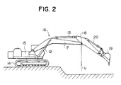
- This hydraulic circuit system is mounted on a hydraulic excavator shown in Fig. 2.
- the hydraulic excavator comprises a lower travel body 14, an upper swing 15, and a front mechanism 16 supported on the upper swing 15, the front mechanism 16 being consisted of a boom 17, an arm 18 and a bucket 19.
- the actuator 12 is a boom cylinder for driving the boom 17 of the front mechanism 16, and the actuator 13 is an arm cylinder for driving the arm 18.
- the hydraulic circuit system of Fig. 1 can be constituted to include circuit sections necessary for supplying the hydraulic fluid to those actuators as well.
- the hydraulic fluid supply source 11 has a hydraulic pump 22 of variable displacement type driven by a prime mover 21, and a pump regulator 23 of load sensing type for controlling a flow rate of the hydraulic fluid delivered from the hydraulic pump 22.
- the pump regulator 23 comprises a working cylinder 24 coupled to a swash plate 22a of the hydraulic pump 22 for driving the swash plate 22a, and a control valve 25 for controlling operation of the working cylinder 24.
- the control valve 25 has a pair of drive parts in opposite relation, one of which is subjected to a delivery pressure of the hydraulic pump 22 and the other of which is subjected to a control pressure (described later).
- the control valve 25 also has a spring 26 for setting a target value of the load sensing differential pressure.
- the hydraulic fluid supply source 11 further has an unloading valve 28 which is operated in response to the differential pressure between the pump delivery pressure and the maximum load pressure for not only limiting a transient rise of the differential pressure, but also holding the pump delivery pressure at a specified value in a neutral condition of the valve apparatus 10, and a relief value 29 for specifying the highest value of the pump delivery pressure.
- valve apparatus 10 is provided with a directional control valve 31 and a pressure controller 32 for controlling a flow of the hydraulic fluid supplied to the boom cylinder 12, and a directional control valve 33 and a pressure controller 34 for controlling a flow of the hydraulic fluid supplied to the arm cylinder 13.
- the directional control valve 31 comprises a supply passage 35 communicating with the hydraulic fluid supply source 11, a pair of load passages 36, 37 communicating with the head side 12a and the rod side 12b of the boom cylinder 12, respectively, intermediate passages 38, 39 capable of selectively communicating with the pair of load passages 36, 37, a pair of discharge passages 40, 41 communicating with the reservoir 27, and a valve spool 42 movable in the axial direction to selectively change over the communication between the above passages.
- the valve spool 42 is formed in a passage communicating between the supply passage 35 and the intermediate passage 38 with a pair of variable restricting sections 43, 44 which can continuously vary their opening areas from a closed state to a certain preset degree in accordance with an amount of movement of the valve spool 42.
- valve spool 42 Depending on the opening areas of the variable restricting sections 43, 44, the flow rates of the hydraulic fluid supplied to the head side 12a and the rod side 12b of the boom cylinder 12 are respectively regulated.
- the opposite ends of the valve spool 42 are subjected to pilot pressures Pa1, Pa2 led from pilot valves (not shown), so that the valve spool 42 is shifted in response to the pilot pressures.
- the directional control valve 33 is constituted in a like manner and comprises a supply passage 45, a pair of load passages 46, 47, intermediate passages 48, 49, a pair of discharge passages 50, 51, a valve spool 52, and a pair of variable restricting sections 53, 54.
- the load passage 46 is communicated with the head side 12a of the arm cylinder 13, and the load passage 47 is communicated with the rod side 12b of the arm cylinder 13, respectively.
- the opposite ends of the valve spool 52 are subjected to pilot pressures Pb1, Pb2 led from pilot valves (not shown), so that the valve spool 52 is shifted in response to the pilot pressures.
- the aforesaid pressure controller 32 is disposed between the intermediate passages 38 and 39, i.e., between the variable restricting sections 43, 44 and the load passages 36, 37, such that outlet pressures of the variable restricting sections 43, 44 act in the valve-opening direction and the control pressure (described later) acts on the valve-closing direction, thereby holding a differential pressure across each of the variable restricting sections 43, 44 at a predetermined value.
- the pressure controller 34 is disposed between the intermediate passages 48 and 49, i.e., between the variable restricting sections 53, 54 and the load passages 46, 47, such that outlet pressures of the variable restricting sections 43, 44 act in the valve-opening direction and the control pressure (described later) acts on the valve-closing direction, thereby holding a differential pressure across each of the variable restricting sections 53, 54 at a predetermined value.
- the valve apparatus 10 further includes detection lines 57, 58 branched from the intermediate passages 39, 49 for receiving or introducing the load pressures developed upon operations of the boom cylinder 12 and the arm cylinder 13, respectively; higher pressure selector means for selecting higher one of the load pressures introduced from the detection lines 57, 58, i.e., the maximum load pressure, for example, check valves 59, 60 disposed in the detection lines 57, 58 for blocking off flows of the hydraulic fluid directed to the intermediate passages 39, 49, respectively; control lines 61, 62 for introducing the maximum load pressure selected by the check valves 59, 60, as the control pressure, to the pressure controllers 32, 34, the control valve 25 of the pump regulator 23, and the unloading valve 28; as well as a line 63 and a restrictor 64 for lowering pressures in the control lines 61, 62 down to a pressure of the reservoir 27 when the directional control valves 31, 33 are returned to their neutral positions.
- higher pressure selector means for selecting higher one of the load pressures introduced from
- valve spools 42, 52 are also formed with connection passages 71, 72 for cutting off the communication between the intermediate passages 39, 49 and the corresponding load passages 36, 46 when the variable restricting sections 43, 53 are closed, and for communicating the intermediate passages 39, 49 with the corresponding load passages 36, 46 when the variable restricting sections 43, 53 are opened.
- connection passages 71, 72 Disposed in the connection passages 71, 72 are check valves 73, 74 to prevent flows of the hydraulic fluid directing from the load passages 36, 46 toward the intermediate passages 39, 49, respectively.
- the valve spool 52 is further formed with a connection passage 75 for cutting off the communication between the intermediate passage 49 and the corresponding load passage 47 when the variable restricting section 54 is closed, and for communicating the intermediate passage 49 with the corresponding load passage 47 when the variable restricting section 54 is opened.
- a check valve 76 Disposed in the connection passage 75 is a check valve 76 to prevent a flow of the hydraulic fluid directing from the load passage 47 toward the intermediate passage 49.
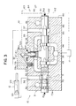
- Fig. 3 shows the hardware arrangement of a section of the directional control valve 31 and the pressure controller 32 in the valve apparatus 10.
- the valve apparatus 10 has a valve block 80 in which there are formed parts of the aforesaid passages 35 - 41 and detection lines 57.
- the valve spool 42 is disposed to be axially slidable in a bore 81 formed through the valve block 80.
- the pressure controller 32 and the check valves 59, 73 are urged by weak springs 32a, 59a, 73a in the valve-closing direction, respectively.
- the variable restricting sections 43, 44 are each defined around the valve spool 42 in the form of plural notches.
- variable restricting section 43 When the valve spool 42 is moved rightwardly from an illustrated neutral position, the variable restricting section 43 is opened and the intermediate passage 39 is communicated with the load passage 36 through the connection passage 71 and the check valve 73 within the valve spool 42. At the same time, the other load passage 37 is communicated with the discharge passage 41 through an annular recess 85 and notches 86 both formed around the valve spool 42. Conversely, when the valve spool 42 is moved leftwardly from the illustrated position, the variable restricting section 44 is opened and the intermediate passage 39 is communicated with the load passage 37 through the annular recess 85 which functions as a connection passage. At the same time, the load passage 36 is communicated with the discharge passage 40 through the connection passage 71 and the check valve 73.
- valve apparatus 10 has a small valve block 82 integrally combined with the valve block 80.
- the small valve block 82 there are formed the rest of the detection line 17 and a part of the control line 61.
- the part of the control line 61 is communicated via a passage 83 with a chamber 84 in which the spring 32a for the pressure controller 32 is accommodated.
- the hardware arrangement of a section of the directional control valve 33 and the pressure controller 34 are substantially the same as that shown in Fig. 3, excepting that the opposite end sides of the valve spool 52 are each formed to have the arrangement corresponding to the connection passage 71 and the check valve 73.
- the delivery pressure of the hydraulic pump 22 is introduced to the supply passages 35, 45, the variable restricting sections 43, 53 or 44 or 54 and the intermediate passages 38, 48, whereby the pressure controllers 32, 34 are pushed upwardly in Fig. 1, respectively.
- the hydraulic fluid having passed through the pressure controllers 32, 34 are supplied to the boom cylinder 12 and the arm cylinder 13 via the intermediate passages 39, 49, the connection passages 71, 72 and the load passages 36, 46, or the intermediate passages 39, 49, the connection passages 85, 75 and the load passages 37, 47, respectively, whereby the boom cylinder 12 and the arm cylinder 13 are simultaneously driven.
- the load pressure of the boom cylinder 12 is introduced to the intermediate passage 39 via the load passage 36 or 37, and then to the control line 61 via the detection line 57 and the check valve 59.
- the load pressure of the arm cylinder 13 is introduced to the intermediate passage 49 via the load passage 46 or 47, and then to the control line 61 via the detection line 58 and the check valve 60.
- higher one of the load pressures of the boom cylinder 12 and the arm cylinder 13, i.e., the maximum load pressure is taken as the control pressure in the control line 61.
- This control pressure is then applied to the pressure controllers 32, 34, whereby the pressure controllers 32, 34 are lowered from the aforesaid ascended state against the supply pressure from the hydraulic pump 22.
- pressures in the intermediate passages 38, 48 i.e., outlet pressures of the variable restricting section 43, 53 or 44, 54, are increased so that the pressures in the intermediate passages 38, 48 are controlled to become equal to each other.
- inlet pressures of the variable restricting sections 43, 53 or 44, 54 of the valve spools 42, 52 are given by the pressures in the supply passages 35, 45, i.e., the delivery pressure of the hydraulic pump 22, and hence are equal to each other.
- the inlet pressures of the variable restricting section 43, 53 or 44, 54 i.e., the pressures in the intermediate passages 38, 48, are equal to each other as mentioned above. Accordingly, the respective differential pressures across the valve spools 42, 52 are always equal to each other.
- control pressure in the control line 61 i.e., the maximum load pressure between the boom cylinder 12 and the arm cylinder 13
- the pump delivery pressure in the control line 62 is introduced to one drive part of the control valve 25 of the pump regulator 23 via the control line 62
- the pump delivery pressure is introduced to the other drive part of the control valve 25, allowing the control valve 25 to be controlled based on the balance of a force of the spring 26 with a force dependent on the differential pressure between the pump delivery pressure and the maximum load pressure.
- the delivery rate of the hydraulic pump 22 is thereby controlled so that the differential pressure between the pump delivery pressure and the maximum load pressure is held coincident with the target value set by the spring 26, as explained above.
- the hydraulic fluid is supplied to the boom cylinder 12 and the arm cylinder 13 at the flow rates dependent on respective restricting amounts, i.e., opening areas, of the variable restricting sections 43, 53 or 44, 54 corresponding to stroke amounts of the valve spools 42, 52. Therefore, the boom cylinder 12 and the arm cylinder 13 can be simultaneously driven in a stable manner without affecting from one to the other on account of their load fluctuations.
- the check valve 73 is disposed in the connection passage 71 within the valve spool 42 of the directional control valve 31 associated with the boom cylinder 12, and the check valves 74, 76 are disposed in the connection passages 72, 75 within the valve spool 52 of the directional control valve 33 associated with the arm cylinder 13, as explained above.
- This arrangement allows the following operation.
- the swash plate 22a of the hydraulic pump 22 is controlled to be held at a minimum tilting position, and the pump delivery pressure is held at a low level by the unloading valve 28, e.g., about 20 kg/cm2, for preventing energy loss during the neutral condition.
- the variable restricting section 43 is opened and so is the connection passage 71.
- the pump delivery pressure is low on the order of 20 kg/cm2, while the holding pressure of the boom cylinder 12 is as high as 100 kg/cm2, as mentioned above. Accordingly, the hydraulic fluid will not be supplied to the boom cylinder 12 until the pump delivery pressure exceeds the holding pressure as the delivery rate of the hydraulic pump 22 increases.
- the aforesaid holding pressure of 100 kg/cm2 produced in the load passage 36 would cause the hydraulic fluid in the load passage 36 to flow into the detection line 57, the check valve 59 and the control lines 61, 62 owing to and dependent on compressibility of oil as a working fluid, the volume of the detection line 57 and control lines 61, 62, an operation stroke of the check valve 59, and leakage from hydraulic equipment such as the pressure controllers 32, 34 and the restrictor 64. Therefore, even though the directional control valve is shifted with an intention of further lifting the boom, the boom cylinder 12 would be momentarily moved in the direction of contraction to lower the boom 17.
- the check valve 73 is disposed in the connection passage 71 for blocking off a flow of the hydraulic fluid in the load passage 36 toward the intermediate passage 39, the hydraulic fluid in the load passage 36 is prevented from flowing out into the detection line 57, the check valve 59 and the control lines 61, 62, when the valve spool 42 is shifted in such a way. Consequently, the movement of the boom cylinder 12 in the direction of contraction is avoided to positively prevent a drop of the boom 17.
- the 20 kg/cm2 delivery pressure of the hydraulic pump 22 is transmitted, upon opening of the variable restricting section 43, to the control valve 25 of the pump regulator 23 via the pressure controller 32, the detection line 57, the check valve 59 and the control lines 61, 62.
- the pump delivery pressure and the control pressure both acting on the pump regulator 23 are equal to each other at 20 kg/cm2.
- the pump regulator 23 starts increasing the delivery rate of the hydraulic pump 22 in order to raise the pump delivery pressure Accordingly, the pump regulator 23 is subjected to a pressure sufficiently lower than the holding pressure of the boom 12, making it possible to control the pump delivery rate in a stable manner. In addition, no large load acts on the pump regulator 23 in a moment, making it also possible to prevent damages of the equipment and prolong the service life.
- the hydraulic pump 22 continues to increase its delivery rate until the differential pressure across the variable restricting section 43, which is produced upon the hydraulic fluid passing therethrough, becomes equal to a pressure, e.g., 15 kg/cm2, set by the pressure controller 32.
- a pressure e.g. 15 kg/cm2 set by the pressure controller 32.
- the flow rate of the hydraulic fluid supplied to the head side 12a of the boom cylinder 12 becomes equal to the flow rate dependent on the opening area of the variable restricting section 43.
- the hydraulic fluid is supplied to the head side 12a at the constant flow rate, whereby the boom cylinder 12 is moved in the direction of extension to lift the boom 17 at the same rate.
- the hydraulic fluid in the load passage 47 would flow into the detection line 58, the check valve 60 and the control lines 61, 62 at the moment of the shifting if the check valve 75 were not disposed in the connection passage 75 of the valve spool 52.
- the check valve 76 since the check valve 76 is disposed in the connection passage 75, the hydraulic fluid in the load passage 47 is prevented from flowing toward the intermediate passage 49, and the foregoing flow-out of the hydraulic fluid upon shifting of the valve spool 52 is prevented with certainty.
- This makes it possible to prevent not only an extension of the arm cylinder 13 to lower the arm 18, but also a resultant drop of the arm 18, at the moment when the valve spool 52 is shifted.
- the control line 62 since the control line 62 is kept from being subjected to the high holding pressure in a moment, the pump regulator 23 can be controlled in a stable manner, which reduces a probability of damaging the equipment and prolongs the service life.
- the check valve(s) 73 or 74, 76 serve to prevent the hydraulic fluid in the load passage(s) 36 or 46, 47 from flowing out therefrom, resulting in positive prevention of a drop of the boom 17 or the arm 18. Also, since the high holding pressure is not directly introduced to the control line 62, it is possible to perform stable control of the pump regulator 23, reduce a probability of damaging the equipment, and prolong the service life.
- FIG. 4 A second embodiment of the present invention will be described with reference to Fig. 4.
- This embodiment adopts a different valve structure as pressure regulating means for controlling the differential pressure across the variable restricting section of the directional control valve.
- the remaining arrangement is substantially the same as that of the first embodiment.
- the identical components to those shown in Fig. 1 are designated by the same reference characters.
- a valve apparatus 10A of this embodiment comprises a directional control valve 31A for controlling the flow rate and direction of the hydraulic fluid supplied to a boom cylinder 12, a pressure compensating valve 32A disposed upstream of the directional control valve 31A for controlling a differential pressure across the directional control valve 31A, a directional control valve 33A for controlling the flow rate and direction of the hydraulic fluid supplied to an arm cylinder 13, and a pressure compensating valve 34A disposed upstream of the directional control valve 33A for controlling a differential pressure across the directional control valve 33A.
- the directional control valve 31A comprises an intermediate passage 80 communicated with a supply passage 35 through the pressure compensating valve 32A, a pair of load passages 36, 37 communicating with the head side 12a and the rod side 12b of the boom cylinder 12, respectively, a discharge passage 81 communicating with a reservoir 27, and a valve spool 42A movable in the axial direction to selectively change over the communication between the above passages.
- the valve spool 42A is formed in a passage communicating between the intermediate passage 80 and the load passages 36, 37 with a pair of variable restricting sections 43, 44 which can continuously vary their opening areas from a closed state to a certain preset degree in accordance with an amount of movement of the valve spool 42A.
- a check valve 82 is disposed in the intermediate passage 80 to prevent a flow of the hydraulic fluid from the valve spool 42A toward the pressure compensating valve 32A.
- the directional control valve 33A is constituted in a like manner and comprises an intermediate passage 83, a pair of load passages 46, 47, a discharge passage 84, a valve spool 52A, a pair of variable restricting sections 53, 54, and a check valve 85.
- the valve apparatus 10A also includes a detection line 57A branched from passages 86, 87 located between the variable restricting sections 43, 44 of the valve spool 42A and the pair of load passages 36, 37 for receiving or introducing the load pressure of the boom cylinder 12; a detection line 58A branched from passages 88, 89 located between the variable restricting sections 53, 54 of the valve spool 52A and the pair of load passages 46, 47 for receiving or introducing the load pressure of the arm cylinder 13; shuttle valves 90, 91 for selecting the highest one of the load pressures introduced from the detection lines 57A, 58A and the load pressures of other actuators (not shown), i.e., the maximum load pressure; as well as control lines 61, 62 for introducing the selected maximum load pressure, as a control pressure, to the pressure compensating valves 32A, 34A, a control valve 25 of a pump regulator 23, and an unloading valve 28.
- a detection line 57A branched from passages
- the pressure compensating valve 32A is disposed between the supply passage 35 and the intermediate passage 80, whereas the pressure compensating valve 34A is disposed between the supply passage 45 and the intermediate passage 83.
- the pressure compensating valve 32A has one drive part 32a which is subjected to a control force Fa1 given by both a pressure upstream of the pressure compensating valve 32A, i.e., a pump delivery pressure Ps, and a load pressure PL1 of the boom cylinder 12 in the direction of opening the pressure compensating valve 32A, and the other drive part 32b which is subjected to a control force Fa2 given by both a pressure downstream of the pressure compensating valve 32A, i.e., an inlet pressure PZ1 of the valve spool 42A, and a pressure in the control line 61, i.e., a maximum load pressure Pamax in the direction of closing the pressure compensating valve 32A.
- the pressure compensating valve 34A has one drive part 34a which is subjected to a control force Fb1 given by both the pump delivery pressure Ps and a load pressure PL2 of the arm cylinder 13 in the direction of opening the pressure compensating valve 34A, and the other drive part 34b which is subjected to a control force Fb2 given by both a pressure downstream of the pressure compensating valve 34A, i.e., an inlet pressure PZ2 of the valve spool 52A, and the maximum load pressure Pamax in the direction of closing the pressure compensating valve 34A.
- valve spool 42A constituting the directional control valve 31A there is disposed a check valve 73 downstream of a point where the passage 86 is branched from the detection line 57A, for blocking off a flow of the hydraulic fluid from the load passage 36 toward the variable restricting section 43.
- valve spool 52A constituting the directional control valve 33A there are disposed check valves 74, 76 downstream of a point where the passages 88, 89 are branched from the detection line 58A, for blocking off flows of the hydraulic fluid from the load passages 46, 47 toward the variable restricting sections 53, 54.
- a differential pressure between the pump pressure Ps and the maximum load pressure Pamax i.e., a load sensing differential pressure is ⁇ PLS
- the pressure receiving or bearing area of the drive part of the pressure compensating valve 32A subjected to the load pressure PL1 is aL1
- the pressure receiving area of the drive part thereof subjected to the load pressure PZ1 is aZ1
- the pressure receiving area of the drive part thereof subjected to the pump pressure Ps is as1
- the pressure receiving area of the drive part thereof subjected to the maximum load pressure Pamax is am1
- the pressure receiving area of the drive part of the pressure compensating valve 34A subjected to the load pressure PL2 is aL2
- the pressure receiving area of the drive part thereof subjected to the load pressure PZ2 is aZ2
- the pressure receiving area of the drive part thereof subjected to the pump pressure Ps is as2, and the pressure receiving area of the
- the pressure compensating valves 32A, 34A function so that such variations in the load pressure on one side will not affect operation of the actuator on the other side, and vice versa, whereby the differential pressure across the valve spool 42A for the boom cylinder 12 and the differential pressure across the valve spool 52A for the arm cylinder 13 are held at the same value of ⁇ PLS.
- the distribution ratio of the hydraulic fluid delivered from the hydraulic pump 22 and supplied to the boom cylinder 12 and the arm cylinder 13 is kept constant, allowing the hydraulic fluid to be supplied from the hydraulic pump 22 to the boom cylinder 12 and the arm cylinder 13 at the flow rates dependent on respective restricting amounts, i.e., opening areas, of the variable restricting sections 43, 53 or 44, 54 corresponding to stroke amounts of the valve spools 42A, 52A.
- respective restricting amounts i.e., opening areas
- the check valve 73 is provided in the valve spool 42A of the directional control valve 31A for the boom cylinder 12 and the check valves 74, 76 are provided in the valve spool 52A of the directional control valve 33A for the arm cylinder 13, as with the first embodiment.
Landscapes
- Engineering & Computer Science (AREA)
- General Engineering & Computer Science (AREA)
- Mining & Mineral Resources (AREA)
- Civil Engineering (AREA)
- Structural Engineering (AREA)
- Physics & Mathematics (AREA)
- Fluid Mechanics (AREA)
- Mechanical Engineering (AREA)
- Fluid-Pressure Circuits (AREA)
- Operation Control Of Excavators (AREA)
Abstract
Dispositif de soupape (10; 10A) comprenant au moins une soupape de commutation de direction (31; 31A) disposée entre un passage d'alimentation (35) relié à une source d'alimentation en huile sous pression (11) et une paire de passages de charge (36, 37) reliés à un actuateur (12) et présentant une paire de parties à étranglement variable (43, 44) formées dans des bagues de soupape (42; 42A) pouvant se déplacer axialement; un régulateur de pression (32) ou une soupape de compensation de pression (32A) servant à maintenir à une valeur déterminée la différence de pression entre les deux extrémités des parties à étranglement variable; des passages de détection (57, 57A) formant des bifurcations à partir de premiers passages (39; 86; 87) positionnés entre une paire de parties à étranglement variable et une paire de passages de charge et recevant la pression de charge générée par le fonctionnement de l'actuateur; une soupape de retenue (59) ou une soupape à deux voies (90, 91) servant à sélectionner une pression de charge maximale parmi la pression de charge introduite via le passage de détection et les autres pressions de charge; des conduits de commande (61, 62) permettant l'application de la pression de charge maximale en tant que pression de commande sur le régulateur de pression ou sur la soupape de compensation de pression. Le dispositif de soupape ci-décrit comprend d'autres passages (71; 86) et une soupape de retenue (73) qui sont disposés en aval du point de bifurcation des conduits de détection (57; 57A) des premiers passages (39, 86), et qui permettent l'écoulement de l'huile sous pression depuis les premiers passages vers le passage de charge (36) correspondant à l'une (43) des parties à étranglement variable lorsque cette partie est ouverte, mais empêchent le refoulement en sens inverse de l'huile sous pression.
Applications Claiming Priority (2)
| Application Number | Priority Date | Filing Date | Title |
|---|---|---|---|
| JP210043/89 | 1989-08-16 | ||
| JP21004389 | 1989-08-16 |
Publications (2)
| Publication Number | Publication Date |
|---|---|
| EP0438606A1 true EP0438606A1 (fr) | 1991-07-31 |
| EP0438606A4 EP0438606A4 (en) | 1993-07-28 |
Family
ID=16582861
Family Applications (1)
| Application Number | Title | Priority Date | Filing Date |
|---|---|---|---|
| EP19900912392 Withdrawn EP0438606A4 (en) | 1989-08-16 | 1990-08-16 | Valve device and hydraulic circuit device |
Country Status (4)
| Country | Link |
|---|---|
| US (1) | US5146747A (fr) |
| EP (1) | EP0438606A4 (fr) |
| KR (1) | KR950004530B1 (fr) |
| WO (1) | WO1991002902A1 (fr) |
Cited By (4)
| Publication number | Priority date | Publication date | Assignee | Title |
|---|---|---|---|---|
| FR2689575A1 (fr) * | 1992-04-06 | 1993-10-08 | Rexroth Sigma | Distributeur hydraulique à compensation de pression et une sélection de pression maximale pour piloter une pompe et commande hydraulique multiple incluant de tels distributeurs. |
| FR2757222A1 (fr) * | 1996-12-17 | 1998-06-19 | Mannesmann Rexroth Sa | Dispositif de distribution hydraulique multiple |
| EP0620370B2 (fr) † | 1992-10-29 | 2000-12-06 | Hitachi Construction Machinery Co., Ltd. | Dispositif de soupape de commande hydraulique et système à entrainement hydraulique |
| CN108980126A (zh) * | 2018-08-29 | 2018-12-11 | 武汉船用机械有限责任公司 | 一种回油节流的同步液压系统 |
Families Citing this family (19)
| Publication number | Priority date | Publication date | Assignee | Title |
|---|---|---|---|---|
| WO1991002903A1 (fr) * | 1989-08-16 | 1991-03-07 | Kabushiki Kaisha Komatsu Seisakusho | Dispositif de circuit hydraulique |
| EP0491050B1 (fr) * | 1990-07-05 | 1995-04-26 | Hitachi Construction Machinery Co., Ltd. | Systeme de commande hydraulique et agencement de soupapes associees |
| JPH0473403A (ja) * | 1990-07-11 | 1992-03-09 | Nabco Ltd | 油圧回路 |
| JP3216815B2 (ja) * | 1991-01-23 | 2001-10-09 | 株式会社小松製作所 | 圧力補償弁を有する油圧回路 |
| US5289679A (en) * | 1991-05-09 | 1994-03-01 | Hitachi Construction Machinery Co., Ltd. | Hydraulic drive system with pressure compensating valve |
| US5481872A (en) * | 1991-11-25 | 1996-01-09 | Kabushiki Kaisha Komatsu Seisakusho | Hydraulic circuit for operating plural actuators and its pressure compensating valve and maximum load pressure detector |
| JPH06193606A (ja) * | 1992-12-22 | 1994-07-15 | Komatsu Ltd | 圧力補償弁を備えた操作弁 |
| US5579642A (en) * | 1995-05-26 | 1996-12-03 | Husco International, Inc. | Pressure compensating hydraulic control system |
| US5664417A (en) * | 1996-03-20 | 1997-09-09 | Husco International, Inc. | Control valve for prime mover speed control in hydraulic systems |
| DE19615593B4 (de) * | 1996-04-19 | 2007-02-22 | Linde Ag | Hydrostatisches Antriebssystem |
| US5791142A (en) * | 1997-03-27 | 1998-08-11 | Husco International, Inc. | Hydraulic control valve system with split pressure compensator |
| DE19855187A1 (de) * | 1998-11-30 | 2000-05-31 | Mannesmann Rexroth Ag | Verfahren und Steueranordnung zur Ansteuerung eines hydraulischen Verbrauchers |
| WO2000065238A1 (fr) * | 1999-04-26 | 2000-11-02 | Hitachi Construction Machinery Co., Ltd. | Dispositif a circuit hydraulique |
| DE10219719A1 (de) * | 2002-05-02 | 2003-11-27 | Sauer Danfoss Nordborg As Nord | Hydraulische Ventilanordnung |
| DE102008038381B4 (de) | 2007-12-19 | 2018-12-27 | Linde Hydraulics Gmbh & Co. Kg | Hydrostatisches Antriebssystem |
| US7854115B2 (en) * | 2008-04-25 | 2010-12-21 | Husco International, Inc. | Post-pressure compensated hydraulic control valve with load sense pressure limiting |
| DE102012207422A1 (de) * | 2012-05-04 | 2013-11-07 | Robert Bosch Gmbh | Hydraulische Steueranordnung mit Lastdruckminderungund hydraulischer Ventilblock dafür |
| JP6793849B2 (ja) * | 2018-03-28 | 2020-12-02 | 株式会社日立建機ティエラ | 建設機械の油圧駆動装置 |
| IT201900021126A1 (it) * | 2019-11-13 | 2021-05-13 | Walvoil Spa | Circuito idraulico con funzione combinata di compensazione e recupero energetico |
Family Cites Families (20)
| Publication number | Priority date | Publication date | Assignee | Title |
|---|---|---|---|---|
| US2892312A (en) * | 1958-01-27 | 1959-06-30 | Deere & Co | Demand compensated hydraulic system |
| US2971536A (en) * | 1958-06-26 | 1961-02-14 | Caterpillar Tractor Co | Hydraulic control valve throttling mechanism |
| US3884123A (en) * | 1970-08-07 | 1975-05-20 | Int Harvester Co | Flow sensitive hydraulic control valve |
| US3718159A (en) * | 1971-01-20 | 1973-02-27 | Hydraulic Industries | Control valve |
| US3707988A (en) * | 1971-09-24 | 1973-01-02 | Commercial Shearing | Control valves |
| US3782404A (en) * | 1972-06-14 | 1974-01-01 | Commercial Shearing | Adjustable, metered, directional flow control arrangements |
| US3914939A (en) * | 1973-07-11 | 1975-10-28 | Case Co J I | Pressure compensated pump |
| US3911942A (en) * | 1974-03-28 | 1975-10-14 | Gen Signal Corp | Compensated multifunction hydraulic system |
| ZA7696B (en) * | 1975-02-06 | 1976-12-29 | Commercial Shearing | Compensated work port fluid valves and work port compensators |
| US4037410A (en) * | 1976-05-26 | 1977-07-26 | The Cessna Aircraft Company | Hydraulic control valve |
| US4145958A (en) * | 1977-12-02 | 1979-03-27 | Borg-Warner Corporation | Fluid control system with automatically actuated motor port lock-out valves |
| US4184410A (en) * | 1978-03-15 | 1980-01-22 | Caterpillar Tractor Co. | Low pressure signal driven flow control system |
| US4343152A (en) * | 1980-05-16 | 1982-08-10 | Caterpillar Tractor Co. | Load sensing porting arrangement |
| US4510751A (en) * | 1982-04-22 | 1985-04-16 | The Cessna Aircraft Company | Outlet metering load-sensing circuit |
| US4617798A (en) * | 1983-04-13 | 1986-10-21 | Linde Aktiengesellschaft | Hydrostatic drive systems |
| DE3321483A1 (de) * | 1983-06-14 | 1984-12-20 | Linde Ag, 6200 Wiesbaden | Hydraulische einrichtung mit einer pumpe und mindestens zwei von dieser beaufschlagten verbrauchern hydraulischer energie |
| DE3634728A1 (de) * | 1986-10-11 | 1988-04-21 | Rexroth Mannesmann Gmbh | Ventilanordnung zum lastunabhaengigen steuern mehrerer gleichzeitig betaetigter hydraulischer verbraucher |
| JP2542005B2 (ja) * | 1987-09-21 | 1996-10-09 | 日立建機株式会社 | ロ―ドセンシング制御油圧駆動装置 |
| KR920006546B1 (ko) * | 1988-03-23 | 1992-08-08 | 히다찌 겐끼 가부시기가이샤 | 유압구동장치 |
| US5067389A (en) * | 1990-08-30 | 1991-11-26 | Caterpillar Inc. | Load check and pressure compensating valve |
-
1990
- 1990-08-16 WO PCT/JP1990/001045 patent/WO1991002902A1/fr not_active Ceased
- 1990-08-16 EP EP19900912392 patent/EP0438606A4/en not_active Withdrawn
- 1990-08-16 KR KR1019910700261A patent/KR950004530B1/ko not_active Expired - Fee Related
- 1990-08-16 US US07/623,644 patent/US5146747A/en not_active Expired - Lifetime
Cited By (6)
| Publication number | Priority date | Publication date | Assignee | Title |
|---|---|---|---|---|
| FR2689575A1 (fr) * | 1992-04-06 | 1993-10-08 | Rexroth Sigma | Distributeur hydraulique à compensation de pression et une sélection de pression maximale pour piloter une pompe et commande hydraulique multiple incluant de tels distributeurs. |
| EP0566449A1 (fr) * | 1992-04-06 | 1993-10-20 | Rexroth-Sigma | Distributeur hydraulique combinant la compensation de pression et la sélection de pression maximale |
| EP0620370B2 (fr) † | 1992-10-29 | 2000-12-06 | Hitachi Construction Machinery Co., Ltd. | Dispositif de soupape de commande hydraulique et système à entrainement hydraulique |
| FR2757222A1 (fr) * | 1996-12-17 | 1998-06-19 | Mannesmann Rexroth Sa | Dispositif de distribution hydraulique multiple |
| CN108980126A (zh) * | 2018-08-29 | 2018-12-11 | 武汉船用机械有限责任公司 | 一种回油节流的同步液压系统 |
| CN108980126B (zh) * | 2018-08-29 | 2020-06-26 | 武汉船用机械有限责任公司 | 一种回油节流的同步液压系统 |
Also Published As
| Publication number | Publication date |
|---|---|
| KR920701585A (ko) | 1992-08-12 |
| KR950004530B1 (ko) | 1995-05-02 |
| EP0438606A4 (en) | 1993-07-28 |
| WO1991002902A1 (fr) | 1991-03-07 |
| US5146747A (en) | 1992-09-15 |
Similar Documents
| Publication | Publication Date | Title |
|---|---|---|
| US5146747A (en) | Valve apparatus and hydraulic circuit system | |
| US5209063A (en) | Hydraulic circuit utilizing a compensator pressure selecting value | |
| US9080310B2 (en) | Closed-loop hydraulic system having regeneration configuration | |
| EP0366815B1 (fr) | Unite d'entrainement hydraulique pour engin de construction | |
| KR100797729B1 (ko) | 유압구동기계의 액추에이터 제어장치 | |
| US5460001A (en) | Flow control system | |
| US6241212B1 (en) | Hose rupture control valve unit | |
| KR100706594B1 (ko) | 유압 제어 장치 | |
| US5186000A (en) | Hydraulic drive system for construction machines | |
| EP0379595A1 (fr) | Appareil hydrodynamique | |
| EP0614016A1 (fr) | Unite d'entrainement hydraulique pour machine hydraulique | |
| US20130047599A1 (en) | Meterless hydraulic system having load-holding bypass | |
| US11649610B2 (en) | Hydraulic system of construction machine | |
| US11697918B2 (en) | Hydraulic system of construction machine | |
| EP0477370B1 (fr) | Vanne et dispositif d'entrainement hydraulique | |
| JP3768192B2 (ja) | 油圧制御装置 | |
| JPH03260401A (ja) | 土木・建設機械の油圧駆動装置 | |
| JP2005282456A (ja) | 可変容量型油圧ポンプ制御装置 | |
| KR102273327B1 (ko) | 다목적용 유압시스템의 펌프 유량 제어를 위한 유압회로 | |
| JP4933299B2 (ja) | 建設機械の油圧制御装置 | |
| JPH068641B2 (ja) | 油圧回路 | |
| US20230167628A1 (en) | Hydraulic Control Circuit | |
| KR101506743B1 (ko) | 건설기계의 유압펌프 유량제어장치 | |
| JP2555361B2 (ja) | ロ−ドセンシング制御油圧回路装置 | |
| KR20200103537A (ko) | 구동 장치 및 건설 기계 |
Legal Events
| Date | Code | Title | Description |
|---|---|---|---|
| PUAI | Public reference made under article 153(3) epc to a published international application that has entered the european phase |
Free format text: ORIGINAL CODE: 0009012 |
|
| 17P | Request for examination filed |
Effective date: 19901218 |
|
| AK | Designated contracting states |
Kind code of ref document: A1 Designated state(s): DE FR GB IT SE |
|
| A4 | Supplementary search report drawn up and despatched |
Effective date: 19930611 |
|
| AK | Designated contracting states |
Kind code of ref document: A4 Designated state(s): DE FR GB IT SE |
|
| 17Q | First examination report despatched |
Effective date: 19940908 |
|
| STAA | Information on the status of an ep patent application or granted ep patent |
Free format text: STATUS: THE APPLICATION HAS BEEN WITHDRAWN |
|
| 18W | Application withdrawn |
Withdrawal date: 19950309 |