EP0477370B1 - Vanne et dispositif d'entrainement hydraulique - Google Patents
Vanne et dispositif d'entrainement hydraulique Download PDFInfo
- Publication number
- EP0477370B1 EP0477370B1 EP90916057A EP90916057A EP0477370B1 EP 0477370 B1 EP0477370 B1 EP 0477370B1 EP 90916057 A EP90916057 A EP 90916057A EP 90916057 A EP90916057 A EP 90916057A EP 0477370 B1 EP0477370 B1 EP 0477370B1
- Authority
- EP
- European Patent Office
- Prior art keywords
- passage
- pressure
- pair
- load
- passages
- Prior art date
- Legal status (The legal status is an assumption and is not a legal conclusion. Google has not performed a legal analysis and makes no representation as to the accuracy of the status listed.)
- Expired - Lifetime
Links
- 239000012530 fluid Substances 0.000 claims description 72
- 230000001419 dependent effect Effects 0.000 claims description 35
- 230000007935 neutral effect Effects 0.000 claims description 9
- 238000001514 detection method Methods 0.000 description 29
- 230000001105 regulatory effect Effects 0.000 description 14
- 230000001276 controlling effect Effects 0.000 description 11
- 238000011144 upstream manufacturing Methods 0.000 description 11
- 230000000694 effects Effects 0.000 description 7
- 238000006073 displacement reaction Methods 0.000 description 6
- 230000001133 acceleration Effects 0.000 description 4
- 238000010586 diagram Methods 0.000 description 4
- 230000035939 shock Effects 0.000 description 4
- 230000003247 decreasing effect Effects 0.000 description 3
- 238000010276 construction Methods 0.000 description 2
- 230000008602 contraction Effects 0.000 description 2
- 230000000903 blocking effect Effects 0.000 description 1
- 230000008030 elimination Effects 0.000 description 1
- 238000003379 elimination reaction Methods 0.000 description 1
- 230000005484 gravity Effects 0.000 description 1
- 230000004048 modification Effects 0.000 description 1
- 238000012986 modification Methods 0.000 description 1
Images


Classifications
-
- F—MECHANICAL ENGINEERING; LIGHTING; HEATING; WEAPONS; BLASTING
- F15—FLUID-PRESSURE ACTUATORS; HYDRAULICS OR PNEUMATICS IN GENERAL
- F15B—SYSTEMS ACTING BY MEANS OF FLUIDS IN GENERAL; FLUID-PRESSURE ACTUATORS, e.g. SERVOMOTORS; DETAILS OF FLUID-PRESSURE SYSTEMS, NOT OTHERWISE PROVIDED FOR
- F15B11/00—Servomotor systems without provision for follow-up action; Circuits therefor
-
- E—FIXED CONSTRUCTIONS
- E02—HYDRAULIC ENGINEERING; FOUNDATIONS; SOIL SHIFTING
- E02F—DREDGING; SOIL-SHIFTING
- E02F9/00—Component parts of dredgers or soil-shifting machines, not restricted to one of the kinds covered by groups E02F3/00 - E02F7/00
- E02F9/20—Drives; Control devices
- E02F9/22—Hydraulic or pneumatic drives
- E02F9/2221—Control of flow rate; Load sensing arrangements
- E02F9/2232—Control of flow rate; Load sensing arrangements using one or more variable displacement pumps
-
- E—FIXED CONSTRUCTIONS
- E02—HYDRAULIC ENGINEERING; FOUNDATIONS; SOIL SHIFTING
- E02F—DREDGING; SOIL-SHIFTING
- E02F9/00—Component parts of dredgers or soil-shifting machines, not restricted to one of the kinds covered by groups E02F3/00 - E02F7/00
- E02F9/20—Drives; Control devices
- E02F9/22—Hydraulic or pneumatic drives
- E02F9/2278—Hydraulic circuits
- E02F9/2296—Systems with a variable displacement pump
-
- F—MECHANICAL ENGINEERING; LIGHTING; HEATING; WEAPONS; BLASTING
- F15—FLUID-PRESSURE ACTUATORS; HYDRAULICS OR PNEUMATICS IN GENERAL
- F15B—SYSTEMS ACTING BY MEANS OF FLUIDS IN GENERAL; FLUID-PRESSURE ACTUATORS, e.g. SERVOMOTORS; DETAILS OF FLUID-PRESSURE SYSTEMS, NOT OTHERWISE PROVIDED FOR
- F15B13/00—Details of servomotor systems ; Valves for servomotor systems
- F15B13/02—Fluid distribution or supply devices characterised by their adaptation to the control of servomotors
- F15B13/04—Fluid distribution or supply devices characterised by their adaptation to the control of servomotors for use with a single servomotor
- F15B13/0416—Fluid distribution or supply devices characterised by their adaptation to the control of servomotors for use with a single servomotor with means or adapted for load sensing
- F15B13/0417—Load sensing elements; Internal fluid connections therefor; Anti-saturation or pressure-compensation valves
-
- F—MECHANICAL ENGINEERING; LIGHTING; HEATING; WEAPONS; BLASTING
- F15—FLUID-PRESSURE ACTUATORS; HYDRAULICS OR PNEUMATICS IN GENERAL
- F15B—SYSTEMS ACTING BY MEANS OF FLUIDS IN GENERAL; FLUID-PRESSURE ACTUATORS, e.g. SERVOMOTORS; DETAILS OF FLUID-PRESSURE SYSTEMS, NOT OTHERWISE PROVIDED FOR
- F15B2211/00—Circuits for servomotor systems
- F15B2211/30—Directional control
- F15B2211/305—Directional control characterised by the type of valves
- F15B2211/30525—Directional control valves, e.g. 4/3-directional control valve
- F15B2211/3053—In combination with a pressure compensating valve
- F15B2211/30535—In combination with a pressure compensating valve the pressure compensating valve is arranged between pressure source and directional control valve
-
- F—MECHANICAL ENGINEERING; LIGHTING; HEATING; WEAPONS; BLASTING
- F15—FLUID-PRESSURE ACTUATORS; HYDRAULICS OR PNEUMATICS IN GENERAL
- F15B—SYSTEMS ACTING BY MEANS OF FLUIDS IN GENERAL; FLUID-PRESSURE ACTUATORS, e.g. SERVOMOTORS; DETAILS OF FLUID-PRESSURE SYSTEMS, NOT OTHERWISE PROVIDED FOR
- F15B2211/00—Circuits for servomotor systems
- F15B2211/50—Pressure control
- F15B2211/575—Pilot pressure control
- F15B2211/5756—Pilot pressure control for opening a valve
-
- Y—GENERAL TAGGING OF NEW TECHNOLOGICAL DEVELOPMENTS; GENERAL TAGGING OF CROSS-SECTIONAL TECHNOLOGIES SPANNING OVER SEVERAL SECTIONS OF THE IPC; TECHNICAL SUBJECTS COVERED BY FORMER USPC CROSS-REFERENCE ART COLLECTIONS [XRACs] AND DIGESTS
- Y10—TECHNICAL SUBJECTS COVERED BY FORMER USPC
- Y10T—TECHNICAL SUBJECTS COVERED BY FORMER US CLASSIFICATION
- Y10T137/00—Fluid handling
- Y10T137/8593—Systems
- Y10T137/87169—Supply and exhaust
- Y10T137/87177—With bypass
- Y10T137/87185—Controlled by supply or exhaust valve
Definitions
- a flow of a hydraulic fluid supplied from a hydraulic fluid supply source to an actuator is controlled by a valve apparatus including a flow control valve.
- valve apparatus for use in the hydraulic drive system implementing the above load sensing system is disclosed in US-A-4 685 295.
- This disclosed valve apparatus comprises a flow control valve having a supply passage communicating with a hydraulic fluid supply source, a load passage communicating with an actuator, and a first meter-in variable restrictor disposed between the supply passage and the load passage and opened dependent on an operation amount thereof; a first signal passage branched from the load passage downstream of the first variable restrictor and including a restrictor and a check valve allowing a hydraulic fluid to flow toward the load passage; a tank passage communicating with a reservoir tank; a discharge passage for communicating the first signal passage with the tank passage; a second variable restrictor provided in the discharge passage and having its opening variable dependent on the operation amount of the flow control valve to produce in the first signal passage a control pressure different from load pressure; and a second signal passage for leading the control pressure in the first signal passage to the hydraulic fluid supply source, the valve apparatus being featured in further comprising a third signal passage for connecting the first signal passage to the upstream side of
- the pressure upstream of the first variable restrictor is reduced by the restrictor in the third signal passage and then led to the first signal passage.
- the reduced pressure is led as the control pressure to the hydraulic fluid supply source to perform the load sensing control, so that the pump delivery pressure may be controlled not depending on the load pressure.
- the dependency on the load pressure can be assured to some extent in a range above the predetermined operation amount, so that the flow rate dependent on the operation amount of the flow control valve is obtained.
- the first signal passage is branched from the load passage downstream of the first variable restrictor and includes the restrictor, there occurs a flow of the hydraulic fluid passing from the first signal passage through the restrictor therein to the load passage under a normal condition that the operation amount of the flow control valve is so increased as to secure a predetermined differential pressure across the first variable restrictor.
- the control pressure which is produced in the first signal passage by reducing the pressure upstream of the first variable restrictor is lower than the pressure upstream of the first variable restrictor, e.g., the pump pressure, but higher than the pressure downstream of the first variable restrictor, i.e., the load pressure.
- the hydraulic fluid supply source for the load sensing system receives, as an input signal, the differential pressure between the delivery pressure of the hydraulic pump and the aforesaid control pressure to thereby control the delivery rate of the hydraulic pump such that the above differential pressure becomes equal to a preset target value. Accordingly, the smaller differential pressure between the pressure upstream of the first variable restrictor and the control pressure in the first signal passage implies that the target value must be set to a smaller one. The reduced target value leads to the problem that the control gain is also reduced and hunting is more likely to occur.
- the present invention provides a valve apparatus for controlling a flow of a hydraulic fluid supplied from a hydraulic fluid supply source to an actuator, comprising a flow control valve having a supply passage communicating with said hydraulic fluid supply source, a load passage communicating with said actuator, and a first meter-in variable restrictor disposed between said supply passage and said load passage and opened dependent on an operation amount thereof; a first signal passage located downstream of said first variable restrictor and having a passage section for detecting load pressure of said actuator; a tank passage communicating with a reservoir tank; a discharge passage for communicating said first signal passage with said tank passage; and a second variable restrictor provided in said discharge passage and having its opening variable dependent on the operation amount of said flow control valve to produce in said first signal passage a control pressure different from said load pressure, the control pressure in said first signal passage being led to said hydraulic fluid supply source through a second signal passage for controlling the fluid volume supplied by said hydraulic fluid supply source; said valve apparatus comprising auxiliary restrictor means disposed in said first signal passage for reducing the load pressure detected in said passage
- the port pressure of the load passage i.e., the drive pressure of the hydraulic actuator
- A, a1, a2 and AP * the port pressure of the load passage
- the drive pressure of the hydraulic actuator is a function of A, a1, a2 and AP * , assuming that the target pressure to be held by the pressure compensating valve is AP * .
- the drive pressure and the pump delivery pressure can be both obtained dependent on the operation amount of the flow control valve.
- the control pressure is lower than the load pressure, and the differential pressure between the pump delivery pressure and the control pressure is larger than the differential pressure across the first variable restrictor. Therefore, the differential pressure across the first variable restrictor can be set to a normal small value which results in small pressure loss, so that the differential pressure between the pump delivery pressure and the control pressure may be a satisfactorily large value. Consequently, it is possible to increase the control gain of the load sensing system and achieve stable control of the hydraulic pump free from hunting.
- This embodiment pertains to a hydraulic drive system for driving a single-acting actuator.
- the hydraulic drive system of this embodiment comprises a hydraulic fluid supply source made up by a hydraulic pump 1 of variable displacement type and a pump regulator 2 for controlling the displacement volume of the hydraulic pump 1 and constituting a load sensing system, a main relief valve 3 for setting maximum pressure of a hydraulic fluid delivered from the hydraulic pump 1, a single-acting actuator, e.g., a hydraulic motor 4, driven by the hydraulic fluid delivered from the hydraulic pump 1, and a valve apparatus 5 for controlling a flow of the hydraulic fluid supplied from the hydraulic pump 1 to the hydraulic motor 4.
- a hydraulic fluid supply source made up by a hydraulic pump 1 of variable displacement type and a pump regulator 2 for controlling the displacement volume of the hydraulic pump 1 and constituting a load sensing system
- a main relief valve 3 for setting maximum pressure of a hydraulic fluid delivered from the hydraulic pump 1
- a single-acting actuator e.g., a hydraulic motor 4 driven by the hydraulic fluid delivered from the hydraulic pump 1
- a valve apparatus 5 for controlling a flow of the hydraulic fluid supplied from the hydraulic pump 1 to the hydraulic motor
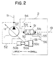
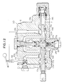
- the pump regulator 2 is detailed in Fig. 2.
- the pump regulator 2 comprises an actuator 50 operatively coupled to a swash plate 1a of the hydraulic pump 1 for controlling the displacement volume of the hydraulic pump 1, and a regulating valve 51 operated in response to the differential pressure Pd - PLXmax between the pump pressure Pd and the maximum control pressure PLXmax for controlling operation of the actuator 50.
- the actuator 50 comprises a double-acting cylinder having a piston 50a having opposite end faces of different pressure receiving areas from each other, and a small-diameter cylinder chamber 50b and a large-diameter cylinder chamber 50c positioned to receive the opposite end faces of the piston 50a, respectively.
- the small-diameter cylinder chamber 50b is communicated with a delivery line 1 b of the hydraulic pump 1 through a line 52, whereas the large-diameter cylinder chamber 50c is selectively communicated with the delivery line 1 b through a line 53, the regulating valve 51 and a line 54, or with a reservoir tank 56 through the line 53, the regulating valve 51 and a line 55.
- the regulating valve 51 has two drive parts 51a, 51b in opposite relation.
- the pump pressure Pd is loaded to one drive part 51a through a line 57 and the line 54, whereas the maximum control pressure PLXmax is loaded to the other drive part 51 b through a signal line 19 as a second signal passage described later.
- a spring 51 c is also disposed in the regulating valve 51 on the same side as the driver part 51 b.
- the regulating valve 51 As the maximum control pressure PLXmax detected by the signal line 19 rises, the regulating valve 51 is shifted leftwardly on the drawing to take an illustrated position. In this state, the large-diameter cylinder chamber 50c of the actuator 50 is communicated with the delivery line 1 b, whereupon the piston 50a is moved leftwardly on the drawing because of the difference in pressure receiving area between the opposite end faces of the piston 50a to increase the tilting amount of the swash plate 1a, i.e., the displacement volume of the hydraulic pump 1. As a result, the pump delivery rate is increased to raise the pump pressure Pd. With the pump pressure Pd raised, the regulating valve 51 is returned back rightwardly on the drawing.
- the regulating valve 51 When the differential pressure Pd - PLXmax reaches a target value determined by the spring 51c, the regulating valve 51 is stopped and the pump delivery rate is kept constant. On the contrary, as the maximum control pressure PLXmax lowers, the regulating valve 51 is shifted rightwardly on the drawing. At this shift position, the large-diameter cylinder chamber 50c of the actuator 50 is communicated with the reservoir tank 56, whereupon the piston 50a is moved rightwardly on the drawing to decrease the tilting amount of the swash plate 1a. As a result, the pump delivery rate is decreased to lower the pump pressure Pd. With the pump pressure Pd lowered, the regulating valve 51 is returned back leftwardly on the drawing.
- the regulating valve 51 When the differential pressure Pd - PLXmax reaches the target value determined by the spring 51 c, the regulating valve 51 is stopped and the pump delivery rate is kept constant. In this manner, the pump delivery rate is controlled such that the differential pressure Pd - PLXmax is held at the target differential pressure determined by the spring 51c.
- the valve apparatus 5 comprises a flow control valve 8 for controlling a flow rate of the hydraulic fluid supplied to the hydraulic motor 4, a pressure compensating valve 9 disposed upstream of the flow control valve 8 for controlling the differential pressure across the flow control valve 8 to supply the hydraulic fluid at a substantially constant flow rate irrespective of fluctuations in the load pressure PL of the hydraulic motor 4 and the pump pressure Pd during the combined operation, a supply passage 11 communicating with the pump 1 through the pressure compensating valve 9, and a load passage 12 capable of communicating with the supply passage 11 and connected to the hydraulic motor 4.
- the flow control valve 8 comprises a spool made up of a spool section 7a, a spool section 7b and a rod 7c integrally formed together.
- the spool section 7a has formed therein a first meter-in variable restrictor 14 having an opening variable dependent on the operation amount of the flow control valve 8, i.e., the spool stroke, to disconnect or connect between the supply passage 11 and the load passage 12, and a detection port 15 opened downstream of the first variable restrictor 14 for fluid communication with the load passage 12 to detect the load pressure of the hydraulic motor 4.
- the valve apparatus 5 also comprises a first signal passage (hereinafter simply referred to as a signal passage) 18 communicating with the detection port 15, a shuttle valve 10 disposed downstream of the signal passage 18, a discharge passage 30 branched from the signal passage 18, and a tank passage 13 communicating with the reservoir tank 56.
- the spool section 7b of the flow control valve 8 has formed therein a second variable restrictor 21 having an opening variable dependent on the spool stroke to connect or disconnect between the discharge passage 11 and the tank passage 13.
- the second variable restrictor 21 is configured such that it is opened with a predetermined opening when the flow control valve 8 is in a neutral position, and is closed after opening of the first variable restrictor 14 when the operation amount of the flow control valve 8, i.e., the spool stroke, increases.
- the signal passage 18 has a fixed restrictor 22 as auxiliary restrictor means disposed between the detection port 15 and the point where the discharge passage 30 is branched from the signal passage 18.
- the shuttle valve 10 serves as higher-pressure selector means for selecting maximum one of control pressures including the control pressure PLX.
- the selected maximum control pressure PLXmax is passed to a signal line 19 as a second signal passage so that the pump regulator 2 is controlled to regulate the displacement volume of the hydraulic pump 1 for implementation of the load sensing load sensing system, as mentioned above.
- the valve apparatus 5 further comprises passages 31, 32 for leading inlet pressure Pz of the first variable restrictor 14 and the control pressure PLX to the pressure compensating valve 9, respectively.
- the pressure compensating valve 9 operates so as to hold differential pressure Pz - PLX between the inlet pressure Pz of the first variable restrictor 14 and the control pressure PLX at substantially constant differential pressure AP * .
- the differential pressure across the flow control valve 8 is controlled to an almost fixed value.
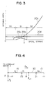
- the second variable restrictor 21 is open with a predetermined opening, and the control pressure in the signal passage 18 is equal to the tank pressure.
- the detection port 15 opens to communicate with the load passage 12 so that the load pressure PL of the hydraulic motor 4 shown in Fig. 1 is led to the detection port 15, as seen from the characteristic line 20b in Fig. 3. In this condition, the second variable restrictor 21 is still open.
- a hydraulic system including the first variable restrictor 14, the detection port 15, the fixed restrictor 22, the signal passage 18, the discharge passage 30, the second variable restrictor 21 and the tank passage 13 can be schematically depicted as shown in Fig. 4.
- the supply pressure i.e., the pump delivery pressure Pd
- the regulating valve 51 of the pump regulator 2 receives the differential pressure AP between the delivery pressure Pd of the hydraulic pump 1 and the control pressure PLX, as an input signal, to control the delivery rate of the hydraulic pump such that the differential pressure AP becomes equal to the fixed value determined by the spring 51c. Accordingly, the smaller differential pressure AP implies that the spring 51c must be set to a small setting value. With the setting value reduced, the control gain is so reduced that hunting is more likely to occur. With this embodiment, the differential pressure ⁇ P as the input signal of the pump regulator 2 can be set to a large value as mentioned above, it is possible to increase the control gain for enabling stable control of the hydraulic pump 1 free from hunting.
- control pressure PLX is created from the load pressure PL using two restrictors; the fixed restrictor 22 and the second variable restrictor 21. This results in the advantageous effect that the flow rate of the hydraulic fluid passing through the signal passage 18 and the discharge passage 30 to the reservoir tank 56 can be reduced, and the pressure control can be achieved with smaller energy loss.
- the restrictor 22 is a fixed one in the above first embodiment, it may be a variable one whose opening is variable dependent on the spool stroke of the flow control valve 8 as will be understood from the foregoing equations (5) through (7). This modification can further improve control characteristics.
- the spool of the flow control valve 8 comprises the spool sections 7a, 7b and the rod 7c integrally formed together
- the rod 7c may be made as a separate member.
- the spool sections 7a, 7b may be arranged to be movable independently and driven by a common pilot pressure.
- either one or both of the first and second variable restrictors 14, 21 may be in the form of a poppet valve.
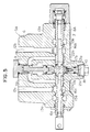
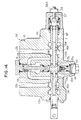
- FIG. 5 is a vertical sectional view of the valve apparatus
- Fig. 6 is a circuit diagram showing the valve apparatus in terms of function.
- the identical components to those shown in Fig. 1 are denoted by the same reference numerals.
- a valve apparatus 5A of this embodiment comprises a block 6 forming a body, a flow control valve 8A having a spool 7 slidable in a spool bore 6a defined in the block 6, a pressure compensating valve 9 provided upstream of the flow control valve 8A to control differential pressure between inlet pressure Pz and outlet pressure PLof the flow control valve 8A, i.e., differential pressure Pz - PL across the flow control valve 8A, and a shuttle valve 10 provided downstream of the flow control valve 8A.
- the block 6 has formed therein two supply passages 11a, 11 b communicating with a hydraulic pump 1, two load passages 12a, 12b capable of communicating with the supply passages 11 a, 11 b, respectively, and connected to a hydraulic actuator shown in Fig. 6, e.g., a swing motor 4A for driving a swing of a hydraulic excavator, and two tank passages 13a, 13b capable of communicating with the load passages 12a, 12b, respectively.
- a hydraulic actuator shown in Fig. 6 e.g., a swing motor 4A for driving a swing of a hydraulic excavator
- tank passages 13a, 13b capable of communicating with the load passages 12a, 12b, respectively.
- the spool 7 is also formed with a second variable restrictor 21a positioned between the passage 17b and the passage 18 and having its opening area variable dependent on the stroke of the spool 7 when the spool 7 is moved rightwardly on the drawing, a second variable restrictor 21 positioned between the passage 17a and the passage 18 and having its opening area variable dependent on the stroke of the spool 7 when the spool 7 is moved leftwardly on the drawing, a fixed restrictor 22a positioned between the passage 17a and the passage 18 and carrying out its function when the spool 7 is moved rightwardly on the drawing, and a fixed restrictor 22b positioned between the passage 17b and the passage 18 and carrying out its function when the spool 7 is moved leftwardly on the drawing.
- the detection port 15a, the passages 16a, 17a and the passage 18 jointly constitute a first signal passage for detecting the load pressure of the swing motor 4A downstream of the first variable restrictor 14a, when the spool 7 is moved rightwardly on the drawing.
- the detection port 15b, the passages 16b, 17b and the passage 18 jointly constitute a first signal passage for detecting the load pressure of the swing motor 4A downstream of the first variable restrictor 14b, when the spool 7 is moved leftwardly on the drawing.
- the detection port 15b and the passages 17b, 16b jointly constitute a discharge passage for communicating the first signal passage 15a, 16a, 17a, 18 established when the spool 7 is moved rightwardly on the drawing, with the tank passage 13b, the second variable restrictor 21a being disposed in this discharge passage.
- the detection port 15a and the passages 17a, 16a jointly constitute a discharge passage for communicating the first signal passage 15b, 16b, 17b, 18 established when the spool 7 is moved leftwardly on the drawing, with the tank passage 13a, the second variable restrictor 21 b being disposed in this discharge passage.
- the control pressure PLX produced in the passage 18 constituting a part of the first signal passage is, similarly to the first embodiment, introduced to a signal line 19 as a second signal passage through the shuttle valve 10 as higher-pressure selector means, and used for the load sensing control by the pump regulator 2.
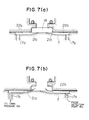
- Figs. 7(a) and 7(b) show a neutral state of the spool 7
- Fig. 7(b) shows a state in which the spool 7 has been moved leftwardly.
- Arrows in Fig. 7(b) indicate a flow of the hydraulic fluid in the signal passage and the discharge passage.
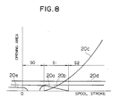
- Fig. 8 Shift timing of the first and second variable restrictors 14a, 14b and 21a, 21b and the detection ports 15a, 15b with respect to the spool stroke of the flow control valve 8A is shown in Fig. 8. Characteristics of the first variable restrictors 14a, 14b, i.e., the relations of their opening areas with respect to the stroke of the spool 7, are set identical to the characteristic line 20c in Fig. 3. Characteristics of the second variable restrictors 21 a, 21 are set identical to the characteristic line 20a in Fig. 3. Characteristics of the fixed restrictors 22a, 22b are set identical to the characteristic line 20d in Fig. 3.
- the opening areas between the detection ports 15a, 15b and the load passages 12a, 12b are set identical to the characteristic line 20b in Fig. 3.
- the characteristic line 20e indicates the opening area between the detection ports 15a, 15b and the tank passages 13a, 13b.
- the swing motor 4A is a double-acting actuator.
- a counter balance valve 35 for blocking off the holding pressure produced when the swing (not shown) is installed on a slope.
- the port pressure, i.e., the drive pressure PL, and the delivery pressure Pd of the hydraulic pump 1 can be controlled dependent on the operation amount of the flow control valve 8A, i.e., the spool stroke, thereby providing the similar advantageous effect to that in the first embodiment.
- the differential pressure AP Pd - PLX between the pump delivery pressure Pd and the control pressure PLX can be a satisfactorily large value.
- the control pressure PLX is created using two restrictors; the fixed restrictor 22a, 22b and the second variable restrictor 21a, 21 b, the flow rate of the hydraulic fluid passing from the detection port 15a, 15b as the signal passage to the tank passage 13b, 13a through the passage 18 and the detection port 15b, 15a as the discharge passage can be reduced, and the pressure control can be achieved with smaller energy loss. In this point, the similar advantageous effect to that in the first embodiment can also be obtained.
- restrictors 22a, 22b are fixed ones in this embodiment, they may be variable ones whose openings are variable dependent on the stroke of the spool 7, as with the foregoing first embodiment.
- a third embodiment of the present invention will be described with reference to Fig. 9. This embodiment is to give the valve apparatus with a function of reserving the holding pressure of the actuator.
- a valve apparatus 5B of this embodiment has second variable restrictors 21a, 21 and fixed restrictors 22a, 22b identical to those in the foregoing second embodiment.
- a check valve 23 with small spring pressure is slidably fitted in a spool 7 which constitutes a flow control valve 8B.
- the passage 16a is connected to the tank passage 13a through the check valve 23, thereby forming the discharge passage.
- the fixed restrictor 22a functions between the detection port 15a and the passage 18, and the supply passage 11 a is communicated with the load passage 12a through the check valve 23 upon opening of the first meter-in variable restrictor 14a.
- the passage 18 is communicated with the tank passage 13a through the second variable restrictor 21 b, the passage 17a, the passage 16a and the check valve 23 which jointly define the discharge passage.
- the dead load of the boom acts on the boom cylinder 4B and the holding pressure is produced in the head side line of the boom cylinder 4B, i.e., the load passage 12a.
- the detection port 15a is first disconnected from the tank passage 13a, and the detection port 15a is then communicated with the load passage 12a. Afterward, the passage 16a is communicated with the supply passage 11a through the first meter-in variable restrictor 14a. Consequently, the first variable restrictor 14a, the fixed restrictor 22a and the second variable restrictor 21a now constitute the foregoing hydraulic system shown in Fig. 4.
- the pressure in the passage 16a is determined by the stroke of the spool within the stroke range where the hydraulic system shown in Fig. 4 is established, and that pressure may be lower than the holding pressure produced in the load passage 12a.
- the check valve 23 acts to prevent the hydraulic fluid from flowing from the load passage 12a to the passage 16a.
- this embodiment can reserve a holding function to prevent contraction of the boom cylinder 4B, i.e., a drop of the boom by the gravity or dead load.
- the third embodiment can control the port pressure (drive pressure) PL and the pump delivery pressure dependent on the spool stroke of the flow control valve 8B, and can achieve force control for regulating thrust of the boom cylinder 4B with the control of the port pressure.
- the third embodiment includes the check valve 23 between the load passage 12a and the first variable restrictor 14a, when the spool 7 shown in Fig. 9 is moved rightwardly to extend the boom cylinder 4B, the hydraulic fluid held under pressure on the head side of the boom cylinder 4B will not flow into the passage 16a, and the boom (not shown) can be prevented from dropping by the dead load upon contraction of the boom cylinder 4B.
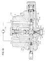
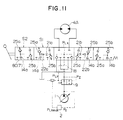
- FIG. 10 Afourth embodiment of the present invention will be described with reference to Figs. 10 and 11.
- This embodiment is to provide a valve apparatus for use in a double-acting actuator which has no counter balance valve.
- a valve apparatus 5C includes a pair of check valves 25a, 25b disposed in a spool 7 of the flow control valve 8C.
- the check valve 25a is disposed between the supply passage 11a and the load passage 12a as well as the tank passage 13a, while the check valve 25b is disposed between the supply passage 11 b and the load passage 12b as well as the tank passage 13b.
- a swing motor 4A having no counter balance valve is provided as an actuator to drive a swing (not shown).
- the holding pressure is produced in either the load passage 12a or 12b both connected to the swing motor 4A.
- the hydraulic system shown in Fig. 4 is established in a range of the region S1 shown in Fig. 11 as mentioned above, and the pressure in the passage 16a or 16b is determined by the stroke of the spool 7, resulting in that the pressure in the passage 16a or 16b may be lower than the holding pressure produced in the load passage 12a, 12b.
- a fifth embodiment of the present invention will be described with reference to Fig. 12.
- This embodiment has an operator check, in place of the check valve, to block off the holding pressure.
- a valve apparatus 5D of this embodiment has an operator check 26 in a load passage 12a which is defined in a block 6 constituting the valve apparatus body and is subjected to the holding pressure of a boom cylinder 4B.
- the remaining structure is identical to that of the third embodiment shown in Fig. 9.
- the foregoing equations (5) through (7) are satisfied on the basis of the hydraulic system including the first variable restrictors 14a, 14b, as well as the corresponding fixed restrictors 22a, 22b and the second variable restrictors 21a, 21 b. Therefore, the port pressure PL and the pump delivery pressure can be controlled dependent on the lever operation amount of the flow control valve 8B.
- the operator check 26 is opened only after the pressure in the load passage 12a becomes larger than the holding pressure acting on the head side of the boom cylinder4B, allowing the hydraulic fluid to be supplied to the head side of the boom cylinder 4B for driving of the boom cylinder 4B. Consequently, the hydraulic fluid boosted in pressure for holding the boom cylinder 4B is prevented from flowing into the supply passage 11a, and the similar advantageous effect to that in the third embodiment of Fig. 9 can be obtained.
- a valve apparatus 5E according to the sixth embodiment, shown in Fig. 13, has a limiter 36 for limiting the operation amount of a flow control valve 8E to a predetermined amount in short of the maximum stroke, in addition to the structure of the foregoing first embodiment shown in Fig. 1.
- the limiter 36 comprises, for example, a projection against which a spool section 7a of the flow control valve 8E strikes for restriction of its movement.
- a maximum value of the stroke restricted by the limiter 36 corresponds to a point X contained in the region S1 of Fig. 3 by way of example.
- this seventh embodiment can also limit the drive pressure of the actuator to be controlled by the valve apparatus 5F, and provide the similar advantageous effect to that in the sixth embodiment.
- a valve apparatus 5G according to the eighth embodiment has a pilot valve 39 and a pressure reducing valve 36B for reducing pilot pressure generated by the pilot valve 39.
- the pressure reducing valve 36B serves as a limiter for limiting the operation amount of a spool 7 of a flow control valve 8G.
- the remaining structure is identical to that of the foregoing second embodiment shown in Fig. 5.
- the maximum pilot pressure i.e., the maximum stroke, can be adjusted using an electric signal.
- the delivery pressure of the hydraulic pump and the drive pressure of the actuator can be controlled dependent on the operation amount of the flow control valve. This reliably eliminates the event that the pump delivery pressure may be increased up to the setting pressure of a main relief valve against the intention of an operator, and ensures excellent operability. Also, the control of the drive pressure permits force control of the actuator so that, when the actuator drives an inertial load, an acceleration of the inertial load may be controlled. As a result, the shock perceived by the operator can be alleviated.
- the load pressure is reduced by a fixed restrictor to create the control pressure
- the differential pressure between the pump delivery pressure and the control pressure can be set to a satisfactorily large value to thereby enable the loading sensing control of the hydraulic pump free from hunting.
- the control pressure is created using two restrictors; i.e., the fixed restrictor and the second variable restrictor, the flow rate of the hydraulic fluid flowing from the signal passage to the reservoir tank through the discharge passage can be reduced so as to achieve the pressure control with small energy loss.
Landscapes
- Engineering & Computer Science (AREA)
- General Engineering & Computer Science (AREA)
- Mining & Mineral Resources (AREA)
- Civil Engineering (AREA)
- Structural Engineering (AREA)
- Physics & Mathematics (AREA)
- Fluid Mechanics (AREA)
- Mechanical Engineering (AREA)
- Fluid-Pressure Circuits (AREA)
Abstract
Claims (15)
l'appareil à soupapes comprenant un dispositif formant un rétrécissement auxiliaire (22 ; 22a, 22b) placé dans le premier passage de signaux (18 ; 16a, 17a, 16b, 17b, 18) et destiné à réduire la pression de charge détectée dans la section de passage (15, 15a, 15b) du premier passage de signaux afin qu'une pression inférieure à la pression détectée de charge soit produite dans le premier passage de signaux sous forme de la pression de commande.
l'appareil à soupapes comprenant une paire de dispositifs auxiliaires de rétrécissement (22a, 22b) placés dans la paire de premiers passages de signaux (16a, 17a, 16b, 17b, 18) pour la réduction de la pression de charge détectée en alternance dans les sections de passage (15a, 15b) de la paire de premiers passages de signaux si bien qu'une pression inférieure à la pression détectée de charge est produite dans le premier passage correspondant de signaux comme pression de commande.
l'appareil à soupapes (5 ; 5A-5G) comprenant un dispositif auxiliaire de rétrécissement (22; 22a, 22b) placé dans le premier passage de signaux (18 ; 16a, 17a, 16b, 17b, 18) et destiné à réduire la pression de charge détectée dans la section de passage (15 ; 15a, 15b) du premier passage de signaux afin qu'une pression inférieure à la pression détectée de charge soit produite dans le premier passage de signaux sous forme de la pression de commande.
Applications Claiming Priority (3)
| Application Number | Priority Date | Filing Date | Title |
|---|---|---|---|
| JP2539/90 | 1990-01-11 | ||
| JP253990 | 1990-01-11 | ||
| PCT/JP1990/001407 WO1991010833A1 (fr) | 1990-01-11 | 1990-11-01 | Vanne et dispositif d'entrainement hydraulique |
Publications (4)
| Publication Number | Publication Date |
|---|---|
| EP0477370A1 EP0477370A1 (fr) | 1992-04-01 |
| EP0477370A4 EP0477370A4 (en) | 1993-05-26 |
| EP0477370B1 true EP0477370B1 (fr) | 1995-10-11 |
| EP0477370B2 EP0477370B2 (fr) | 1998-11-04 |
Family
ID=11532185
Family Applications (1)
| Application Number | Title | Priority Date | Filing Date |
|---|---|---|---|
| EP90916057A Expired - Lifetime EP0477370B2 (fr) | 1990-01-11 | 1990-11-01 | Valve hydraulique |
Country Status (5)
| Country | Link |
|---|---|
| US (1) | US5203678A (fr) |
| EP (1) | EP0477370B2 (fr) |
| KR (1) | KR940008821B1 (fr) |
| DE (1) | DE69022991T3 (fr) |
| WO (1) | WO1991010833A1 (fr) |
Families Citing this family (15)
| Publication number | Priority date | Publication date | Assignee | Title |
|---|---|---|---|---|
| DE69319400T2 (de) * | 1992-04-20 | 1998-12-03 | Hitachi Construction Machinery Co., Ltd., Tokio/Tokyo | Hydraulische schaltungsanordnung für erdbewegungsmaschinen |
| US5245827A (en) * | 1992-08-03 | 1993-09-21 | Deere & Company | Supply valve arrangement for closed center hydraulic system |
| JPH06137276A (ja) * | 1992-10-29 | 1994-05-17 | Komatsu Ltd | 可変容量油圧ポンプの容量制御装置 |
| DE4241848C2 (de) * | 1992-12-11 | 1994-12-22 | Danfoss As | Gesteuertes Proportionalventil |
| DE4313597B4 (de) * | 1993-04-26 | 2005-09-15 | Linde Ag | Verfahren zum Betreiben einer verstellbaren hydrostatischen Pumpe und dafür ausgebildetes hydrostatisches Antriebssystem |
| JPH07127607A (ja) * | 1993-09-07 | 1995-05-16 | Yutani Heavy Ind Ltd | 作業機械の油圧装置 |
| US5937645A (en) * | 1996-01-08 | 1999-08-17 | Nachi-Fujikoshi Corp. | Hydraulic device |
| CN1274810A (zh) * | 1999-05-21 | 2000-11-29 | 株式会社岛津制作所 | 多阀门装置 |
| US6666125B2 (en) | 2002-03-14 | 2003-12-23 | Sauer-Danfoss Inc. | Swing cylinder oscillation control circuit and valve for oscillating booms |
| US7211180B2 (en) * | 2003-02-10 | 2007-05-01 | Robert Bosch Corporation | Contamination-resistant gas sensor element |
| DE10308484A1 (de) * | 2003-02-26 | 2004-09-09 | Bosch Rexroth Ag | Hydraulische Steueranordnung |
| DE10357471A1 (de) * | 2003-12-09 | 2005-07-07 | Bosch Rexroth Ag | Hydraulische Steueranordnung |
| US20060198736A1 (en) * | 2005-03-01 | 2006-09-07 | Caterpillar Inc. | Pump control system for variable displacement pump |
| US20100158706A1 (en) * | 2008-12-24 | 2010-06-24 | Caterpillar Inc. | Pressure change compensation arrangement for pump actuator |
| SE533917C2 (sv) * | 2009-06-24 | 2011-03-01 | Nordhydraulic Ab | Ventilanordning |
Family Cites Families (17)
| Publication number | Priority date | Publication date | Assignee | Title |
|---|---|---|---|---|
| US3856436A (en) * | 1972-12-18 | 1974-12-24 | Sperry Rand Corp | Power transmission |
| US4167893A (en) * | 1978-02-06 | 1979-09-18 | Eaton Corporation | Load sensing valve |
| US4428400A (en) * | 1979-02-28 | 1984-01-31 | Atos Oleodinamica S.P.A. | Electrically and hydraulically actuated flow-distributing valve unit |
| US4336687A (en) * | 1980-04-21 | 1982-06-29 | Eaton Corporation | Load sensing controller |
| US4457341A (en) * | 1982-03-04 | 1984-07-03 | Vickers, Incorporated | Variable pressure drop proportional motor controlled hydraulic directional valve |
| US4617798A (en) * | 1983-04-13 | 1986-10-21 | Linde Aktiengesellschaft | Hydrostatic drive systems |
| US4515181A (en) * | 1983-05-25 | 1985-05-07 | Caterpillar Tractor Co. | Flow control valve assembly wth quick response |
| DE3436246C2 (de) * | 1984-10-03 | 1986-09-11 | Danfoss A/S, Nordborg | Steuereinrichtung für einen hydraulisch betriebenen Verbraucher |
| DE3515732A1 (de) * | 1985-05-02 | 1986-11-06 | Danfoss A/S, Nordborg | Steuereinrichtung fuer mindestens einen hydraulisch betriebenen verbraucher |
| US4738279A (en) * | 1985-12-17 | 1988-04-19 | Linde Aktiengesellschaft | Multiway valves with load feedback |
| JPS61266801A (ja) * | 1986-05-09 | 1986-11-26 | Daikin Ind Ltd | 油圧モ−タで駆動される旋回台を有する車両 |
| US4781219A (en) * | 1986-10-10 | 1988-11-01 | Eaton Corporation | Fluid controller and dampening fluid path |
| DE3634728A1 (de) * | 1986-10-11 | 1988-04-21 | Rexroth Mannesmann Gmbh | Ventilanordnung zum lastunabhaengigen steuern mehrerer gleichzeitig betaetigter hydraulischer verbraucher |
| DE3802672C2 (de) * | 1988-01-29 | 1993-12-16 | Danfoss As | Hydraulisches Steuerventil mit Druckfühleinrichtung |
| JP2683244B2 (ja) * | 1988-04-14 | 1997-11-26 | 株式会社ゼクセル | 制御弁 |
| JPH0786361B2 (ja) * | 1988-11-10 | 1995-09-20 | 株式会社ゼクセル | 油圧制御弁 |
| US4914913A (en) * | 1989-05-03 | 1990-04-10 | Caterpillar Inc. | Load responsive flow amplified control system for power steering |
-
1990
- 1990-11-01 WO PCT/JP1990/001407 patent/WO1991010833A1/fr not_active Ceased
- 1990-11-01 EP EP90916057A patent/EP0477370B2/fr not_active Expired - Lifetime
- 1990-11-01 KR KR1019910700309A patent/KR940008821B1/ko not_active Expired - Fee Related
- 1990-11-01 US US07/655,368 patent/US5203678A/en not_active Expired - Lifetime
- 1990-11-01 DE DE69022991T patent/DE69022991T3/de not_active Expired - Fee Related
Also Published As
| Publication number | Publication date |
|---|---|
| EP0477370A1 (fr) | 1992-04-01 |
| WO1991010833A1 (fr) | 1991-07-25 |
| KR920701732A (ko) | 1992-08-12 |
| EP0477370B2 (fr) | 1998-11-04 |
| EP0477370A4 (en) | 1993-05-26 |
| DE69022991D1 (de) | 1995-11-16 |
| DE69022991T2 (de) | 1996-03-14 |
| KR940008821B1 (ko) | 1994-09-26 |
| US5203678A (en) | 1993-04-20 |
| DE69022991T3 (de) | 1999-07-15 |
Similar Documents
| Publication | Publication Date | Title |
|---|---|---|
| EP0477370B1 (fr) | Vanne et dispositif d'entrainement hydraulique | |
| US5873245A (en) | Hydraulic drive system | |
| US5277027A (en) | Hydraulic drive system with pressure compensting valve | |
| EP3301229B1 (fr) | Dispositif d'entraînement hydraulique de machine de travail | |
| US7204084B2 (en) | Hydraulic system having a pressure compensator | |
| US5146747A (en) | Valve apparatus and hydraulic circuit system | |
| US4976106A (en) | Load-sensing variable displacement pump controller with adjustable pressure-compensated flow control valve in feedback path | |
| EP0251172A2 (fr) | Système de commande hydraulique | |
| EP0427865B1 (fr) | Dispositif d'entrainement hydraulique d'un engin de construction | |
| RU2427022C2 (ru) | Дозирующий клапан со встроенной функцией сброса давления и подпитки | |
| US6438952B1 (en) | Hydraulic circuit device | |
| EP0465655B1 (fr) | Dispositif de commande hydraulique d'engins de chantier/genie civil | |
| US4938022A (en) | Flow control system for hydraulic motors | |
| EP0877168A1 (fr) | Dispositif d'entrainement hydraulique | |
| US6397591B1 (en) | Hydraulic driving unit | |
| US7240604B2 (en) | Electro-hydraulic metering valve with integral flow control | |
| US11680385B1 (en) | Ride control valve | |
| US7614335B2 (en) | Hydraulic system with variable standby pressure | |
| EP0586214A1 (fr) | Dispositif de commande pour vérin | |
| JPH09317703A (ja) | 油圧駆動回路 | |
| EP0433454B1 (fr) | Appareil a circuit hydraulique | |
| JP2555361B2 (ja) | ロ−ドセンシング制御油圧回路装置 | |
| EP4729790A1 (fr) | Dispositif de commande de pompe et système de commande de pression de fluide | |
| JP2816024B2 (ja) | 弁装置及び油圧駆動装置 | |
| JPWO1991010833A1 (ja) | 弁装置及び油圧駆動装置 |
Legal Events
| Date | Code | Title | Description |
|---|---|---|---|
| PUAI | Public reference made under article 153(3) epc to a published international application that has entered the european phase |
Free format text: ORIGINAL CODE: 0009012 |
|
| 17P | Request for examination filed |
Effective date: 19910314 |
|
| AK | Designated contracting states |
Kind code of ref document: A1 Designated state(s): DE FR GB IT SE |
|
| A4 | Supplementary search report drawn up and despatched |
Effective date: 19930403 |
|
| AK | Designated contracting states |
Kind code of ref document: A4 Designated state(s): DE FR GB IT SE |
|
| 17Q | First examination report despatched |
Effective date: 19950130 |
|
| GRAA | (expected) grant |
Free format text: ORIGINAL CODE: 0009210 |
|
| RBV | Designated contracting states (corrected) |
Designated state(s): DE GB IT |
|
| AK | Designated contracting states |
Kind code of ref document: B1 Designated state(s): DE GB IT |
|
| REF | Corresponds to: |
Ref document number: 69022991 Country of ref document: DE Date of ref document: 19951116 |
|
| ITF | It: translation for a ep patent filed | ||
| PLBI | Opposition filed |
Free format text: ORIGINAL CODE: 0009260 |
|
| PLBF | Reply of patent proprietor to notice(s) of opposition |
Free format text: ORIGINAL CODE: EPIDOS OBSO |
|
| 26 | Opposition filed |
Opponent name: LINDE AKTIENGESELLSCHAFT, WIESBADEN Effective date: 19960711 |
|
| PLBF | Reply of patent proprietor to notice(s) of opposition |
Free format text: ORIGINAL CODE: EPIDOS OBSO |
|
| PLBF | Reply of patent proprietor to notice(s) of opposition |
Free format text: ORIGINAL CODE: EPIDOS OBSO |
|
| PLAW | Interlocutory decision in opposition |
Free format text: ORIGINAL CODE: EPIDOS IDOP |
|
| PLAW | Interlocutory decision in opposition |
Free format text: ORIGINAL CODE: EPIDOS IDOP |
|
| PUAH | Patent maintained in amended form |
Free format text: ORIGINAL CODE: 0009272 |
|
| STAA | Information on the status of an ep patent application or granted ep patent |
Free format text: STATUS: PATENT MAINTAINED AS AMENDED |
|
| 27A | Patent maintained in amended form |
Effective date: 19981104 |
|
| AK | Designated contracting states |
Kind code of ref document: B2 Designated state(s): DE GB IT |
|
| ITF | It: translation for a ep patent filed | ||
| REG | Reference to a national code |
Ref country code: GB Ref legal event code: IF02 |
|
| PGFP | Annual fee paid to national office [announced via postgrant information from national office to epo] |
Ref country code: DE Payment date: 20061026 Year of fee payment: 17 |
|
| PGFP | Annual fee paid to national office [announced via postgrant information from national office to epo] |
Ref country code: GB Payment date: 20061101 Year of fee payment: 17 |
|
| PGFP | Annual fee paid to national office [announced via postgrant information from national office to epo] |
Ref country code: IT Payment date: 20061130 Year of fee payment: 17 |
|
| GBPC | Gb: european patent ceased through non-payment of renewal fee |
Effective date: 20071101 |
|
| PG25 | Lapsed in a contracting state [announced via postgrant information from national office to epo] |
Ref country code: DE Free format text: LAPSE BECAUSE OF NON-PAYMENT OF DUE FEES Effective date: 20080603 |
|
| PG25 | Lapsed in a contracting state [announced via postgrant information from national office to epo] |
Ref country code: GB Free format text: LAPSE BECAUSE OF NON-PAYMENT OF DUE FEES Effective date: 20071101 |
|
| PG25 | Lapsed in a contracting state [announced via postgrant information from national office to epo] |
Ref country code: IT Free format text: LAPSE BECAUSE OF NON-PAYMENT OF DUE FEES Effective date: 20071101 |