EP0438932A1 - Hydromechanisme Steuervorrichtung zur Ausgabe eines Fluidstromes - Google Patents
Hydromechanisme Steuervorrichtung zur Ausgabe eines Fluidstromes Download PDFInfo
- Publication number
- EP0438932A1 EP0438932A1 EP90403345A EP90403345A EP0438932A1 EP 0438932 A1 EP0438932 A1 EP 0438932A1 EP 90403345 A EP90403345 A EP 90403345A EP 90403345 A EP90403345 A EP 90403345A EP 0438932 A1 EP0438932 A1 EP 0438932A1
- Authority
- EP
- European Patent Office
- Prior art keywords
- receiver
- motor
- shaft
- pump
- cam
- Prior art date
- Legal status (The legal status is an assumption and is not a legal conclusion. Google has not performed a legal analysis and makes no representation as to the accuracy of the status listed.)
- Withdrawn
Links
Images

Classifications
-
- F—MECHANICAL ENGINEERING; LIGHTING; HEATING; WEAPONS; BLASTING
- F04—POSITIVE - DISPLACEMENT MACHINES FOR LIQUIDS; PUMPS FOR LIQUIDS OR ELASTIC FLUIDS
- F04B—POSITIVE-DISPLACEMENT MACHINES FOR LIQUIDS; PUMPS
- F04B49/00—Control, e.g. of pump delivery, or pump pressure of, or safety measures for, machines, pumps, or pumping installations, not otherwise provided for, or of interest apart from, groups F04B1/00 - F04B47/00
- F04B49/02—Stopping, starting, unloading or idling control
- F04B49/022—Stopping, starting, unloading or idling control by means of pressure
-
- G—PHYSICS
- G05—CONTROLLING; REGULATING
- G05D—SYSTEMS FOR CONTROLLING OR REGULATING NON-ELECTRIC VARIABLES
- G05D16/00—Control of fluid pressure
- G05D16/20—Control of fluid pressure characterised by the use of electric means
- G05D16/2006—Control of fluid pressure characterised by the use of electric means with direct action of electric energy on controlling means
- G05D16/208—Control of fluid pressure characterised by the use of electric means with direct action of electric energy on controlling means using a combination of controlling means as defined in G05D16/2013 and G05D16/2066
Definitions
- the invention relates to a hydromechanical control device for the distribution of a fluid flow which pressurizes single-acting hydraulic receivers such as jacks, brake or clutch cylinders.
- the invention also relates to a hydraulic circuit comprising a flow generator constituted by a volumetric hydraulic pump, with one or two flow directions, driven by an electric motor whose direction of rotation and the magnitude of the torque are controlled by an electronic circuit, especially from a setpoint.
- the pressurization of the receiver is obtained by the flow generated by the pump.
- the pressure reached in steady state at the receiver is approximately proportional to the torque delivered by the engine.
- Such a hydraulic circuit is known from the publication FR-A 2 620 097.
- a problem encountered in this circuit lies in that the energy is consumed during the pressure maintenance cycles of the circuit without displacement of the receiver.
- the invention relates to a device for switching a fluid flow rate as a function of the direction of rotation of the pump shaft of a hydraulic circuit.
- Another object of the invention is to insulate the hydraulic receiver in the absence of rotation of the shaft and maintain the pressure of said receiver without energy consumption.
- the invention also relates to the command for switching the fluid flow rate and the isolation of the receiver by means of a torque control device delivered by the engine.
- a hydromechanical control device for distributing a fluid flow in which an electric motor drives a pressurizing pump of a hydraulic receiver is characterized in that the motor shaft controls a mechanical actuation means for a receiver pressure relief valve; in order to avoid modification of the state of said receiver during engine and pump stops or to allow the decompression of said receiver during the reversal of the direction of rotation of the motor shaft.
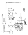
- the device represented in FIG. 1 schematically shows an electric motor 1 supplied from a processing circuit 2 which transforms the signals supplied by sensors such as a sensor 33 delivering a signal representative of a set pressure and a sensor 23 delivering a signal representative of the effective pressure of a hydraulic receiver.
- a first one-way clutch such as a freewheel 4
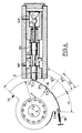
- the driven part of which is constituted by a cam 5 with return spring 18 and with stroke limited by movable stops 25, 26 whose profile Evolutionary 6 is defined by angular sectors of radius R1 and R2 and by angles ⁇ , ⁇ , ⁇ and or ⁇ , ⁇ 1, ⁇ 2, ⁇ 3, ⁇ as shown in Figures 3 and 4.
- the shaft 3 is extended by a drive shaft 7 of a second unidirectional clutch such as a freewheel 8, the driven part 9 of which is coupled to the drive shaft 10 of the pump 11.
- a second unidirectional clutch such as a freewheel 8
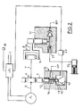
- the pump 11 can be constituted either by a volumetric pump with two flow directions as shown in FIG. 1, or by a valve pump shown schematically in FIG. 2.
- the cam 5 of the motor 1 is supported on a spring finger 12 of constant or variable section of actuation of a sequential control valve 13 constituted for example according to the examples described by a ball 14 capable of coming to rest on its seat 15 under the action of a return spring 17.
- the valve 13 is connected, as shown in Figures 1 and 2, in the form a relief valve (fig. 3) or a relief valve with throttle (fig. 4).
- the pump 11 supplies the hydraulic receiver such as a spring-acting single-acting cylinder 20 which actuates a load.
- the hydraulic circuit comprises a high pressure channel HP and a low pressure channel BP to which are connected non-return valves 21, 22 and a pressure sensor 23 delivering a signal to the treatment circuit 2.
- the freewheel 4 ensures the free rotation of the shaft 3 relative to the cam 5.
- the properly calibrated spring 18 returns the cam 5 to a stop 25.
- the cam 5 traverses the angle ⁇ and its external radius goes from the value R2 to the value R1 (R1 ⁇ R2).
- the finger 12 moves on a race R2 - R1 under the action of the springs 16 and 17 and releases the ball 14 which closes the seat 15. This isolates the HP from the BP.
- a device has thus been produced which makes it possible to open or close the valve 13 as a function of the direction of rotation of the shaft and subsequently to isolate or to put the HP and the BP in communication.
- the engine torque on the shaft 3 acts in the direction determined by the free wheel 4 and drives the cam 5 to an angular position against the opposing torque provided by the spring of reminder 18.
- Each position of the cam 5 corresponds to a position of the actuating finger 12 relative to its guide sleeve 30.
- Preferred positions ( ⁇ 1, ⁇ 2, ⁇ 3) are predetermined by notches 31a, 31b, 31c on the cam 5.
- Each position corresponds to a fluid passage section between the guide sleeve 30 and the finger 12 with variable section 34 of conical configuration.
- an increasing setpoint voltage U delivered by the sensor 33 is imposed on the processing circuit 2.
- the circuit 2 detects a pressure fault using the pressure sensor 23 and then imposes a current on the motor 1 so as to obtain a torque on the shaft 3 in the direction which releases the freewheel device 4 and will engage the freewheel device 8.
- the valve 13 closes and the pump 11 generates a flow of the low pressure towards the receiver 20. This flow generates a pressure as a function of the characteristic dP dV (Pressure / Volume) of the receiver
- circuit 2 When circuit 2 receives the pressure signal equal to the set value delivered by the pressure sensor 23, the supply to motor 1 is interrupted. Pump 11 stops and pressure is maintained at the receiver 20 by the non-return valve 21 without energy consumption.
- the setpoint voltage delivered by the sensor 33 is reduced. From the magnitude of the signal from the pressure sensor 23, the circuit 2 receives a signal corresponding to an excess of pressure , and then imposes on the motor 1 a voltage which makes it possible to reverse the direction of the torque on the shaft 3. The device 4 is disengaged and the device 8 is engaged.
- the pump 11 stops and the valve 13 opens.
- the pressure of the receiver 20 decreases to the set value.
- the electronic unit 2 cancels and reverses the voltage of the motor 1 until the decompression of the receiver 20 is stopped.
Landscapes
- Engineering & Computer Science (AREA)
- Physics & Mathematics (AREA)
- Mechanical Engineering (AREA)
- General Engineering & Computer Science (AREA)
- Fluid Mechanics (AREA)
- General Physics & Mathematics (AREA)
- Automation & Control Theory (AREA)
- Rotary Pumps (AREA)
- Control Of Fluid Gearings (AREA)
Applications Claiming Priority (2)
| Application Number | Priority Date | Filing Date | Title |
|---|---|---|---|
| FR9000721 | 1990-01-23 | ||
| FR9000721A FR2657442B1 (fr) | 1990-01-23 | 1990-01-23 | Dispositif de commande hydromecanique de distribution d'un debit de fluide. |
Publications (1)
| Publication Number | Publication Date |
|---|---|
| EP0438932A1 true EP0438932A1 (de) | 1991-07-31 |
Family
ID=9393007
Family Applications (1)
| Application Number | Title | Priority Date | Filing Date |
|---|---|---|---|
| EP90403345A Withdrawn EP0438932A1 (de) | 1990-01-23 | 1990-11-27 | Hydromechanisme Steuervorrichtung zur Ausgabe eines Fluidstromes |
Country Status (2)
| Country | Link |
|---|---|
| EP (1) | EP0438932A1 (de) |
| FR (1) | FR2657442B1 (de) |
Cited By (1)
| Publication number | Priority date | Publication date | Assignee | Title |
|---|---|---|---|---|
| US5271722A (en) * | 1993-01-11 | 1993-12-21 | Sauer Inc. | Automotive control system for hydrostatic pumps |
Citations (2)
| Publication number | Priority date | Publication date | Assignee | Title |
|---|---|---|---|---|
| DE2139362A1 (de) * | 1971-08-06 | 1973-02-15 | Rexroth Gmbh G L | Verfahren und vorrichtung zum regeln der leistung von verstellbaren hydraulikpumpen |
| FR2620097A1 (fr) * | 1987-09-04 | 1989-03-10 | Renault | Dispositif generateur de pression pour circuits de freinage de vehicules automobiles |
-
1990
- 1990-01-23 FR FR9000721A patent/FR2657442B1/fr not_active Expired - Lifetime
- 1990-11-27 EP EP90403345A patent/EP0438932A1/de not_active Withdrawn
Patent Citations (2)
| Publication number | Priority date | Publication date | Assignee | Title |
|---|---|---|---|---|
| DE2139362A1 (de) * | 1971-08-06 | 1973-02-15 | Rexroth Gmbh G L | Verfahren und vorrichtung zum regeln der leistung von verstellbaren hydraulikpumpen |
| FR2620097A1 (fr) * | 1987-09-04 | 1989-03-10 | Renault | Dispositif generateur de pression pour circuits de freinage de vehicules automobiles |
Cited By (1)
| Publication number | Priority date | Publication date | Assignee | Title |
|---|---|---|---|---|
| US5271722A (en) * | 1993-01-11 | 1993-12-21 | Sauer Inc. | Automotive control system for hydrostatic pumps |
Also Published As
| Publication number | Publication date |
|---|---|
| FR2657442A1 (fr) | 1991-07-26 |
| FR2657442B1 (fr) | 1992-04-17 |
Similar Documents
| Publication | Publication Date | Title |
|---|---|---|
| FR2635364A1 (fr) | Amortisseur de vibrations hydraulique regulable pour vehicule automobile | |
| EP0524032B1 (de) | Druckregeleinrichtung für hydraulischen Schaltkreis | |
| FR2654788A1 (fr) | Variateur de vitesse. | |
| EP0452174B1 (de) | Elektrisch betätigte Druckregeleinrichtung für Hydraulikschaltung | |
| FR2517740A1 (fr) | Dispositif de commande d'actionnement des soupapes d'un moteur a combustion interne | |
| FR2750746A1 (fr) | Installation a agent pressurise et un procede pour son utilisation | |
| FR2490726A1 (fr) | Dispositif d'arret pour pompes d'injection de carburant | |
| FR2573711A1 (fr) | Systeme hydraulique de freinage avec regulation du glissement | |
| FR2786238A1 (fr) | Dispositif d'actionnement pour un embrayage a friction | |
| FR2607571A1 (fr) | Soupape a deux obturateurs notamment pour electrovanne de suspension de vehicule | |
| FR2720447A1 (fr) | Dispositif de servocommande, notamment direction assistée. | |
| FR2627253A1 (fr) | Soupape de non-retour hydrauliquement deverrouillable, notamment pour systemes de soutenement hydrauliques | |
| FR2661013A1 (fr) | Systeme de regulation de pression a commande electrique pour un circuit hydraulique. | |
| FR2549561A1 (fr) | Transmission a commande mecanique a rapport variable, a courroie trapezoidale et a poulies extensibles | |
| FR2657442A1 (fr) | Dispositif de commande hydromecanique de distribution d'un debit de fluide. | |
| CH368358A (fr) | Appareil moteur à transmission hydraulique | |
| FR2813926A1 (fr) | Dispositif hydraulique a soupapes | |
| FR2602478A1 (fr) | Generateur de pression de freinage | |
| FR2516170A1 (fr) | Ensemble de pompes pour l'injection de combustible | |
| FR2650912A1 (fr) | Commutateur a detection de pression dependant de la temperature et dispositif de commande de pression hydraulique utilisant ce commutateur | |
| FR2964273A1 (fr) | Entrainement lineaire pour une unite d'alimentation en pression et unite ainsi equipee | |
| EP0194928A1 (de) | Drucksteuer-Servoeinrichtung für hydraulische Anlage, insbesondere für Kraftfahrzeugservolenkung | |
| FR2725760A1 (fr) | Electrovalve de regulation de pression hydraulique et application aux circuits de freinage | |
| FR2853033A1 (fr) | Entrainement par roue a friction pour des equipements d'un moteur a combustion interne | |
| EP0520844A1 (de) | Elektroventil für Antiblockiervorrichtung |
Legal Events
| Date | Code | Title | Description |
|---|---|---|---|
| PUAI | Public reference made under article 153(3) epc to a published international application that has entered the european phase |
Free format text: ORIGINAL CODE: 0009012 |
|
| AK | Designated contracting states |
Kind code of ref document: A1 Designated state(s): DE ES GB IT |
|
| K1C3 | Correction of patent application (complete document) published |
Effective date: 19910731 |
|
| 17P | Request for examination filed |
Effective date: 19920106 |
|
| STAA | Information on the status of an ep patent application or granted ep patent |
Free format text: STATUS: THE APPLICATION HAS BEEN WITHDRAWN |
|
| 17Q | First examination report despatched |
Effective date: 19940301 |
|
| 18W | Application withdrawn |
Withdrawal date: 19940314 |