EP0438947B1 - System zum Bestimmen der Position an Bord eines Luftfahrzeugs und seine Anwendungen - Google Patents
System zum Bestimmen der Position an Bord eines Luftfahrzeugs und seine Anwendungen Download PDFInfo
- Publication number
- EP0438947B1 EP0438947B1 EP90403789A EP90403789A EP0438947B1 EP 0438947 B1 EP0438947 B1 EP 0438947B1 EP 90403789 A EP90403789 A EP 90403789A EP 90403789 A EP90403789 A EP 90403789A EP 0438947 B1 EP0438947 B1 EP 0438947B1
- Authority
- EP
- European Patent Office
- Prior art keywords
- landmarks
- memory
- computing unit
- landmark
- computing
- Prior art date
- Legal status (The legal status is an assumption and is not a legal conclusion. Google has not performed a legal analysis and makes no representation as to the accuracy of the status listed.)
- Expired - Lifetime
Links
- 230000015654 memory Effects 0.000 claims description 41
- 238000000034 method Methods 0.000 claims description 15
- 239000011159 matrix material Substances 0.000 claims description 10
- 230000004927 fusion Effects 0.000 claims description 8
- 238000000605 extraction Methods 0.000 claims description 5
- 230000002194 synthesizing effect Effects 0.000 claims 1
- 238000004364 calculation method Methods 0.000 description 48
- 238000005259 measurement Methods 0.000 description 15
- 230000008901 benefit Effects 0.000 description 4
- 238000001514 detection method Methods 0.000 description 3
- 238000010586 diagram Methods 0.000 description 3
- 230000007717 exclusion Effects 0.000 description 3
- 238000009472 formulation Methods 0.000 description 3
- 239000000203 mixture Substances 0.000 description 3
- 238000012545 processing Methods 0.000 description 3
- 238000011282 treatment Methods 0.000 description 3
- 210000004027 cell Anatomy 0.000 description 2
- 230000008859 change Effects 0.000 description 2
- 238000012512 characterization method Methods 0.000 description 2
- 238000002592 echocardiography Methods 0.000 description 2
- 230000006870 function Effects 0.000 description 2
- 230000010354 integration Effects 0.000 description 2
- 230000000737 periodic effect Effects 0.000 description 2
- 238000013439 planning Methods 0.000 description 2
- 230000008569 process Effects 0.000 description 2
- 230000000717 retained effect Effects 0.000 description 2
- 230000007704 transition Effects 0.000 description 2
- 241000135309 Processus Species 0.000 description 1
- 238000009825 accumulation Methods 0.000 description 1
- 230000032683 aging Effects 0.000 description 1
- 238000004458 analytical method Methods 0.000 description 1
- 238000012550 audit Methods 0.000 description 1
- 230000015572 biosynthetic process Effects 0.000 description 1
- 235000019658 bitter taste Nutrition 0.000 description 1
- 238000010276 construction Methods 0.000 description 1
- 238000007796 conventional method Methods 0.000 description 1
- 238000005314 correlation function Methods 0.000 description 1
- 238000011156 evaluation Methods 0.000 description 1
- 238000001914 filtration Methods 0.000 description 1
- 238000003384 imaging method Methods 0.000 description 1
- 238000003331 infrared imaging Methods 0.000 description 1
- 238000009434 installation Methods 0.000 description 1
- 230000004807 localization Effects 0.000 description 1
- 238000007726 management method Methods 0.000 description 1
- 238000012986 modification Methods 0.000 description 1
- 230000004048 modification Effects 0.000 description 1
- 239000003607 modifier Substances 0.000 description 1
- 238000012634 optical imaging Methods 0.000 description 1
- 238000002360 preparation method Methods 0.000 description 1
- 238000013179 statistical model Methods 0.000 description 1
- 238000003786 synthesis reaction Methods 0.000 description 1
Images

Classifications
-
- G—PHYSICS
- G01—MEASURING; TESTING
- G01C—MEASURING DISTANCES, LEVELS OR BEARINGS; SURVEYING; NAVIGATION; GYROSCOPIC INSTRUMENTS; PHOTOGRAMMETRY OR VIDEOGRAMMETRY
- G01C21/00—Navigation; Navigational instruments not provided for in groups G01C1/00 - G01C19/00
- G01C21/005—Navigation; Navigational instruments not provided for in groups G01C1/00 - G01C19/00 with correlation of navigation data from several sources, e.g. map or contour matching
-
- F—MECHANICAL ENGINEERING; LIGHTING; HEATING; WEAPONS; BLASTING
- F41—WEAPONS
- F41G—WEAPON SIGHTS; AIMING
- F41G7/00—Direction control systems for self-propelled missiles
- F41G7/34—Direction control systems for self-propelled missiles based on predetermined target position data
- F41G7/343—Direction control systems for self-propelled missiles based on predetermined target position data comparing observed and stored data of target position or of distinctive marks along the path towards the target
-
- G—PHYSICS
- G05—CONTROLLING; REGULATING
- G05D—SYSTEMS FOR CONTROLLING OR REGULATING NON-ELECTRIC VARIABLES
- G05D1/00—Control of position, course, altitude or attitude of land, water, air or space vehicles, e.g. using automatic pilots
- G05D1/12—Target-seeking control
Definitions
- the present invention relates to an on-board system for determining the position of an air vehicle, which can be used both for the automatic guidance of said vehicle (in particular but not exclusively in the case of an unmanned vehicle) and for the provision of assistance to the driver of a controlled vehicle.
- inertial navigation systems using an inertial unit, have advantages of autonomy compared to the environment and discretion, which is particularly appreciable for military vehicles intended to penetrate into enemy territory.
- the current position of the vehicle is determined by updating a previous position using the integration of accelerometric and gyrometric measurements. As a result, they are subject to drifts which must be compensated for so that the current position of the vehicle can be known with sufficient precision.
- these periodic readjustment measurements result from the correlation between the current image of the terrain being overflown provided by an on-board sensor and an image of reference of the terrain to be overflown, this reference image being established before the flight and stored in a memory provided on board said air vehicle.
- the altimeter the image is then constituted by the terrain relief
- millimeter radar millimeter radiometer
- infrared or optical imaging systems or even laser.
- the reference image includes all the information equivalent to that which said sensor is capable of giving for the current image, that is to say that it is necessary to learn the all of the terrain to be overflown for the quantity measured by the sensor and for all observation conditions.
- Such learning is difficult, if not impossible, to acquire with sufficient reliability; in any case, it is delicate and time-consuming to develop.
- the object of the present invention is to remedy these drawbacks.
- the system according to the present invention makes it possible to determine the position of said aerial vehicle, only from discrete landmarks and not, as in the prior art, from all of the elements of a map. This results in savings in computing and memory capacities.
- reference maps are easier and simpler to produce.
- said discrete landmarks are treated one by one and not in their entirety.
- said calculation means calculate, for the information coming from said first comparison device, the probability that each bitter recognized by said sensitive means belongs to each of said types of bitters, that said second memory contains for each bitter describes by its geographical position the probability that said bitter has of being of each of said types of bitters and that said second comparison device compares, for each of the bitters contained in said second memory, the probabilities of being of each of said types of landmarks with similar probabilities delivered by said first comparison device for a landmark recognized by said sensitive means.
- said sensitive means comprise a plurality of different sensors.
- said second comparison device infers said probabilities according to rules developed from the theory of evidence of Dempster and Shafer, while the determination of the unique innovation by said calculation means is implemented. by Bar Shalom's PDAF technique.
- the system according to the present invention can be used in a navigation aid system or in an automatic guidance system.
- a display device is provided on which the output signals of the KALMAN filter are displayed; in the second, devices using the output signals from the KALMAN filter are arranged to act on the control members in the direction of said vehicle.
- the system according to the invention shown schematically in Figure 1, is intended to be mounted on board a aerial vehicle (not shown). It includes a set of sensors 1, calculation means 2 receiving the signals from said set of sensors 1 and intended to deliver the position of said air vehicle with respect to landmarks detected by said set 1, means 3 for extracting the characteristics of said landmarks detected, a first memory 4 containing the general characteristics of particular landmarks, a comparison device 5 receiving the output signals from the extraction means 3 and from said first memory 4, a second memory 6 containing the positions of said particular landmarks capable of '' be encountered on the ground overflown by said aerial vehicle, calculation means 7 and a KALMAN filter assembly 8.
- the system according to the present invention does not process, at a given instant, the image of an entire area of land, but a small local image, suitable for enabling the recognition of particular landmarks.
- the characteristics corresponding to those retained for the different types of preselected landmarks are determined by means 3.
- the characteristics obtained at the output of the means 3 are then compared in the device 5 with similar characteristics available in the first memory 4, for each type li preselected.
- the statistical distribution models of these characteristic measures then allow the calculation means 7 to evaluate the probability that one has of being in front of a bitter of each of the types li listed. Knowing the possible errors of the statistical model can moreover make it possible to define this probability in an uncertain manner, that is to say for example by an interval of possible probabilities ⁇ (l).
- the second memory 6 there is also a map of the landmarks belonging to one or the other of the types li listed, for the envisaged navigation area.
- the system is in fact presented here in such a way as to leave the latitude to use uncertain landmarks by the information available on them, for example because of information aging, an inappropriate means of analysis or poor quality, etc.
- the inference of these uncertain probabilities advantageously takes into account the "certain” probability that each of the landmarks listed in the second memory 6 of being the landmark detected, taking into account its position and the statistical characteristics of the position estimate delivered by the prediction filter of the device 8. The result of this operation provides an overall "certain" probability that each of the landmarks in the area of uncertainty of navigation will be the landmark detected.
- the PDAF technique is usually used to track targets when their detection is carried out in an environment with a high rate of false alarms; it then allows the appropriate management of false echoes and lack of detection.
- the ambiguities in identity and location of the bitters can be assimilated to such false echoes of position measurement of the detected bitter, that is to say of the position of the air vehicle when taking into account counts the relative position measurement between the vehicle and the detected landmark, provided by the calculation means 2 to the assembly 8.
- additional position information can be supplied (at 9) to said assembly 8 by an inertial unit (not shown).
- the information produced by the KALMAN filter of the assembly 8, relative to the state of navigation (position and speed of the vehicle in particular), is then available at the output of said assembly for a vehicle guidance module, or for a display, depending on the application envisaged.
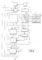
- Figure 2 there is shown in block diagram, a practical embodiment of the system according to the invention.
- the calculation means 7 consist of several calculation units 10, 11, 12, 17 and 18, while the assembly 8 comprises several calculation units 13, 14 and 15, as well as the KALMAN 16 filter itself.
- the assembly 8 comprises several calculation units 13, 14 and 15, as well as the KALMAN 16 filter itself.
- the calculation means 2 develop a vector z for measuring the relative position of the landmark detected by the sensors 1 relative to the vehicle.
- the position measurements extracted from the different sensors 1 supply the different successive components of this vector.
- the calculation unit 13 connected to the calculation means 2 and to the KALMAN filter 16, makes it possible to estimate the absolute position (A) of the bitter observed. D artir of the estimated D osition y of the vehicle issued by said filter 16. as well as the covariance matrix S of the innovation on the position of the bitter observed, from the predicted covariance matrix P on the state estimation error (filter 16), and knowing the matrix d observation H of the system:
- the calculation unit 10 connected to the memory 6 and to the calculation unit 13 operates a statistical windowing of the landmarks referenced at A k in the navigation map (memory 6), that is to say a first selection bitters a priori sufficiently probable thanks to their proximity to the bitter observed, estimated at A; they are chosen on the basis of the condition: where the constants y allows to adjust the probability chosen for the association of A k and of ⁇ .
- This fusion is carried out according to the classical Dempster inference rules to provide masses m LRC ( ⁇ k ) only to the hypotheses ⁇ k , to the exclusion of any set of these hypotheses (property linked to the similarity of the masses m L ): or : ⁇ denoting any possible combination of hypotheses ⁇ k .
- the calculation unit 14 connected to the calculation unit 12, makes it possible to evaluate the innovation of the filter, ⁇ , according to the classic PDAF technique, the probabilities ⁇ k of associating the detected bitter with the bitters referenced in A k after taking into account the recognition information (unit 12) being given by the masses m LRC ⁇ k ):
- the filter 16 also provides the output P of the system, that is to say the prediction of the state x ⁇ at the instants, possibly intermediate, suitable for guiding or viewing, depending on the application envisaged.
- the characteristic extraction means 3, associated with the comparison device 5, carry out the local treatments carried out at each sensor, and specific to each of these sensors, with a view to recognizing the bitter observed.
- these treatments deliver, for each sensor, an interval of probabilities that this bitter is of a given (or unknown) type, and this for all the types listed a priori .
- the bounds of each interval are assimilated to the notions of support S j (I i ) and of plausibility P j (I i ) of the theory of evidence, relative to each hypothesis of identity I i and to each of the M sensors j .
- This calculation unit 17 therefore has a logical function for managing conjunctions, and a function for calculating masses.
- the system of the invention can be used on board an unmanned vehicle (missile, drone, etc.) or on board an aircraft.
- the sensors 1 supply the system 2 to 8 described in the above chapter which supplies a guide module 21 with the state of the machine (position, speed, etc.) available at its output P.
- the guide module 21 develops , taking into account the purpose of the mission, the trajectory to be followed, which it communicates to a piloting module 22, which then draws up the orders to be sent to the control members 23 of the control surfaces 24 of the craft, so as to slaving on the nominal path defined by the guide module 21.
- the output of the system 2 to 8 described can be sent to a display unit (not shown) available to the pilot or the navigator.
Landscapes
- Engineering & Computer Science (AREA)
- Radar, Positioning & Navigation (AREA)
- Remote Sensing (AREA)
- Automation & Control Theory (AREA)
- Physics & Mathematics (AREA)
- General Physics & Mathematics (AREA)
- Aviation & Aerospace Engineering (AREA)
- Chemical & Material Sciences (AREA)
- Combustion & Propulsion (AREA)
- General Engineering & Computer Science (AREA)
- Navigation (AREA)
- Radar Systems Or Details Thereof (AREA)
- Electric Propulsion And Braking For Vehicles (AREA)
Claims (8)
Applications Claiming Priority (2)
| Application Number | Priority Date | Filing Date | Title |
|---|---|---|---|
| FR9000331A FR2657160B1 (fr) | 1990-01-12 | 1990-01-12 | Systeme embarque pour determiner la position d'un vehicule aerien et ses applications. |
| FR9000331 | 1990-01-12 |
Publications (2)
| Publication Number | Publication Date |
|---|---|
| EP0438947A1 EP0438947A1 (de) | 1991-07-31 |
| EP0438947B1 true EP0438947B1 (de) | 1994-02-16 |
Family
ID=9392717
Family Applications (1)
| Application Number | Title | Priority Date | Filing Date |
|---|---|---|---|
| EP90403789A Expired - Lifetime EP0438947B1 (de) | 1990-01-12 | 1990-12-27 | System zum Bestimmen der Position an Bord eines Luftfahrzeugs und seine Anwendungen |
Country Status (8)
| Country | Link |
|---|---|
| US (1) | US5208757A (de) |
| EP (1) | EP0438947B1 (de) |
| CA (1) | CA2033872C (de) |
| CH (1) | CH684127A5 (de) |
| DE (1) | DE69006709T2 (de) |
| DK (1) | DK0438947T3 (de) |
| ES (1) | ES2050409T3 (de) |
| FR (1) | FR2657160B1 (de) |
Families Citing this family (33)
| Publication number | Priority date | Publication date | Assignee | Title |
|---|---|---|---|---|
| US5525883A (en) * | 1994-07-08 | 1996-06-11 | Sara Avitzour | Mobile robot location determination employing error-correcting distributed landmarks |
| US5646857A (en) * | 1995-03-31 | 1997-07-08 | Trimble Navigation Limited | Use of an altitude sensor to augment availability of GPS location fixes |
| FR2736146B1 (fr) * | 1995-06-28 | 1997-08-22 | Aerospatiale | Systeme de guidage en alignement d'un missile sur une cible |
| US5774826A (en) * | 1995-11-30 | 1998-06-30 | Trimble Navigation Limited | Optimization of survey coordinate transformations |
| WO1998010307A1 (en) | 1996-09-09 | 1998-03-12 | Dennis Jay Dupray | Location of a mobile station |
| US6236365B1 (en) | 1996-09-09 | 2001-05-22 | Tracbeam, Llc | Location of a mobile station using a plurality of commercial wireless infrastructures |
| US9134398B2 (en) | 1996-09-09 | 2015-09-15 | Tracbeam Llc | Wireless location using network centric location estimators |
| GB2335324B (en) * | 1998-03-13 | 2003-02-19 | Marconi Gec Ltd | Improvements in or relating to navigational systems |
| US6360193B1 (en) * | 1998-09-17 | 2002-03-19 | 21St Century Systems, Inc. | Method and system for intelligent agent decision making for tactical aerial warfare |
| US9875492B2 (en) * | 2001-05-22 | 2018-01-23 | Dennis J. Dupray | Real estate transaction system |
| US10684350B2 (en) | 2000-06-02 | 2020-06-16 | Tracbeam Llc | Services and applications for a communications network |
| US10641861B2 (en) | 2000-06-02 | 2020-05-05 | Dennis J. Dupray | Services and applications for a communications network |
| US6822583B2 (en) * | 2002-08-12 | 2004-11-23 | Bae Systems Information And Electronic Systems Integration Inc. | Method for passive “360-degree coverage” tactical fighter target tracking incorporating adaptive pilot maneuver cue processing |
| US7132961B2 (en) * | 2002-08-12 | 2006-11-07 | Bae Systems Information And Electronic Systems Integration Inc. | Passive RF, single fighter aircraft multifunction aperture sensor, air to air geolocation |
| US7191056B2 (en) * | 2005-01-04 | 2007-03-13 | The Boeing Company | Precision landmark-aided navigation |
| US7631834B1 (en) | 2006-02-24 | 2009-12-15 | Stealth Robotics, Llc | Aerial robot with dispensable conductive filament |
| ES2345995T3 (es) * | 2006-09-15 | 2010-10-07 | Saab Ab | Dispositivo de simulacion y procedimiento de simulacion de a bordo. |
| US8178825B2 (en) * | 2007-10-29 | 2012-05-15 | Honeywell International Inc. | Guided delivery of small munitions from an unmanned aerial vehicle |
| US8213706B2 (en) * | 2008-04-22 | 2012-07-03 | Honeywell International Inc. | Method and system for real-time visual odometry |
| US20100188280A1 (en) * | 2009-01-23 | 2010-07-29 | Honeywell International Inc. | Systems and methods for determining location of an airborne vehicle using radar images |
| US20110282580A1 (en) * | 2010-05-11 | 2011-11-17 | Honeywell International Inc. | Method of image based navigation for precision guidance and landing |
| US9538493B2 (en) | 2010-08-23 | 2017-01-03 | Finetrak, Llc | Locating a mobile station and applications therefor |
| US8868344B2 (en) * | 2011-09-22 | 2014-10-21 | Honeywell International Inc. | Systems and methods for combining a priori data with sensor data |
| CN102707726B (zh) * | 2012-05-28 | 2014-03-26 | 北京航空航天大学 | 一种无人机目标定位方法 |
| US20170060810A1 (en) * | 2012-12-13 | 2017-03-02 | Eagle Harbor Holdings, LLC. | System and method for the operation of an automotive vehicle system with modeled sensors |
| US9290269B2 (en) | 2013-03-15 | 2016-03-22 | CyPhy Works, Inc. | Spooler for unmanned aerial vehicle system |
| IL227982B (en) * | 2013-08-15 | 2018-11-29 | Rafael Advanced Defense Systems Ltd | Missile system with navigation capability based on image processing |
| US10001376B1 (en) * | 2015-02-19 | 2018-06-19 | Rockwell Collins, Inc. | Aircraft position monitoring system and method |
| EP3454079B1 (de) * | 2017-09-12 | 2023-11-01 | Aptiv Technologies Limited | Verfahren zur bestimmung der angemessenheit eines radarziels als ein positionsorientierungspunkt |
| US10685229B2 (en) | 2017-12-21 | 2020-06-16 | Wing Aviation Llc | Image based localization for unmanned aerial vehicles, and associated systems and methods |
| US11061145B2 (en) * | 2018-11-19 | 2021-07-13 | The Boeing Company | Systems and methods of adjusting position information |
| IL274997B2 (en) | 2020-05-27 | 2023-06-01 | Israel Aerospace Ind Ltd | Location according to Levin Communications |
| CN120742905B (zh) * | 2025-09-03 | 2025-11-07 | 杭州丰坦机器人有限公司 | 一种巡检机器人巡检路径自动纠偏方法 |
Family Cites Families (11)
| Publication number | Priority date | Publication date | Assignee | Title |
|---|---|---|---|---|
| FR2451040A1 (fr) * | 1979-03-08 | 1980-10-03 | Virnot Alain | Procede et dispositif permettant de faire automatiquement le point a bord d'un vehicule pourvu d'un equipement radar |
| DE2938853A1 (de) * | 1979-09-26 | 1981-04-09 | Vereinigte Flugtechnische Werke Gmbh, 2800 Bremen | Flaechennavigationssystem fuer luftfahrzeuge |
| US4602336A (en) * | 1983-05-16 | 1986-07-22 | Gec Avionics Limited | Guidance systems |
| US4584646A (en) * | 1983-06-29 | 1986-04-22 | Harris Corporation | System for correlation and recognition of terrain elevation |
| US4700307A (en) * | 1983-07-11 | 1987-10-13 | General Dynamics Corp./Convair Division | Feature navigation system and method |
| US4829304A (en) * | 1986-05-20 | 1989-05-09 | Harris Corp. | Map-aided navigation system employing TERCOM-SITAN signal processing |
| GB2212687A (en) * | 1987-11-17 | 1989-07-26 | Gen Electric Co Plc | Vehicle navigation |
| US4891762A (en) * | 1988-02-09 | 1990-01-02 | Chotiros Nicholas P | Method and apparatus for tracking, mapping and recognition of spatial patterns |
| US4939663A (en) * | 1988-04-04 | 1990-07-03 | Harris Corporation | Elevation map-referenced mechanism for updating vehicle navigation system estimates |
| US5086396A (en) * | 1989-02-02 | 1992-02-04 | Honeywell Inc. | Apparatus and method for an aircraft navigation system having improved mission management and survivability capabilities |
| DE3915633A1 (de) * | 1989-05-12 | 1990-11-15 | Dornier Luftfahrt | Verfahren zur navigation |
-
1990
- 1990-01-12 FR FR9000331A patent/FR2657160B1/fr not_active Expired - Fee Related
- 1990-12-27 DK DK90403789.2T patent/DK0438947T3/da active
- 1990-12-27 DE DE69006709T patent/DE69006709T2/de not_active Expired - Fee Related
- 1990-12-27 ES ES90403789T patent/ES2050409T3/es not_active Expired - Lifetime
- 1990-12-27 EP EP90403789A patent/EP0438947B1/de not_active Expired - Lifetime
-
1991
- 1991-01-09 CA CA002033872A patent/CA2033872C/fr not_active Expired - Fee Related
- 1991-01-11 US US07/639,987 patent/US5208757A/en not_active Expired - Fee Related
- 1991-01-14 CH CH87/91A patent/CH684127A5/fr not_active IP Right Cessation
Also Published As
| Publication number | Publication date |
|---|---|
| CH684127A5 (fr) | 1994-07-15 |
| US5208757A (en) | 1993-05-04 |
| CA2033872C (fr) | 2000-10-03 |
| EP0438947A1 (de) | 1991-07-31 |
| DE69006709D1 (de) | 1994-03-24 |
| CA2033872A1 (fr) | 1991-07-13 |
| DE69006709T2 (de) | 1994-08-25 |
| FR2657160B1 (fr) | 1992-05-07 |
| ES2050409T3 (es) | 1994-05-16 |
| FR2657160A1 (fr) | 1991-07-19 |
| DK0438947T3 (da) | 1994-06-27 |
Similar Documents
| Publication | Publication Date | Title |
|---|---|---|
| EP0438947B1 (de) | System zum Bestimmen der Position an Bord eines Luftfahrzeugs und seine Anwendungen | |
| EP0586302B1 (de) | Bordnavigationssystem für ein Flugzeug mit einem Seitensichtradar mit synthetischer Apertur | |
| EP2513668B1 (de) | Verfahren zur georeferenzierung eines abgebildeten bereichs | |
| EP0565399A1 (de) | Verfahren und Vorrichtung zur Grundkollisionsvermeidung für Flugzeuge | |
| US20220398825A1 (en) | Method for generating 3d reference points in a map of a scene | |
| FR2961897A1 (fr) | Filtre de navigation pour un systeme de navigation par correlation de terrain | |
| EP0357515A1 (de) | Terrestrisches Navigationssystem, das die Position eines Fahrzeugs in der Realzeit darstellt | |
| EP0675374A1 (de) | Verfahren zur Verfolgung beweglicher Körper | |
| FR2736149A1 (fr) | Dispositif de reconnaissance et de poursuite d'objets | |
| WO2021099493A1 (fr) | Procédé d'aide à l'atterrissage d'un aéronef sur une piste d'atterrissage | |
| FR3005187A1 (fr) | Recalage d'images sar par information mutuelle. | |
| FR3016694A1 (fr) | Procede d'assistance a la navigation pour giravion, par affichage dynamique d'une representation du monde exterieur construite en vol instantanement et/ou en differe | |
| US20120274766A1 (en) | Method for classifying objects in an imaging surveillance system | |
| FR2582390A1 (fr) | Systeme de localisation d'un point de navigation | |
| EP4587897A1 (de) | Verfahren zur steuerung der flugbahn eines flugzeugs | |
| EP4588030A1 (de) | Navigationsverfahren und -vorrichtung für ein flugzeug und zugehöriges system, flugzeug, computerprogramm und datenspeichermedium | |
| EP2366094A1 (de) | Verfahren zum korrigieren der barometrischen höhe eines flugzeugs, das in einem flugleitzentrum implementiert wird | |
| EP4217681B1 (de) | Verfahren zur aktualisierung einer vielzahl von landmarken und zugehöriges computerprogrammprodukt und aktualisierungsvorrichtung | |
| WO2024056973A1 (fr) | Procede et dispositif de navigation pour un vehicule, systeme, vehicule, programme d'ordinateur et support d'informations associes | |
| JP7824479B1 (ja) | 推定システム、推定方法、および推定プログラム | |
| EP4006491B1 (de) | Navigationshilfssystem für einen frachtträger mithilfe von landmarken | |
| FR3080177A1 (fr) | Securisation d’une cartographie de conduite autonome | |
| EP4073465B1 (de) | Teilchenfilterungsverfahren und navigationssystem mit messkorrelation | |
| Butenuth et al. | Analysis of image sequences for the detection and monitoring of moving traffic | |
| FR3096142A1 (fr) | Procédé de géolocalisation d'une plateforme se déplaçant en formation avec d'autres plateformes, produit programme d'ordinateur et module de géolocalisation associes |
Legal Events
| Date | Code | Title | Description |
|---|---|---|---|
| PUAI | Public reference made under article 153(3) epc to a published international application that has entered the european phase |
Free format text: ORIGINAL CODE: 0009012 |
|
| AK | Designated contracting states |
Kind code of ref document: A1 Designated state(s): BE DE DK ES GB IT NL SE |
|
| 17P | Request for examination filed |
Effective date: 19910809 |
|
| 17Q | First examination report despatched |
Effective date: 19930208 |
|
| GRAA | (expected) grant |
Free format text: ORIGINAL CODE: 0009210 |
|
| AK | Designated contracting states |
Kind code of ref document: B1 Designated state(s): BE DE DK ES GB IT NL SE |
|
| GBT | Gb: translation of ep patent filed (gb section 77(6)(a)/1977) |
Effective date: 19940216 |
|
| REF | Corresponds to: |
Ref document number: 69006709 Country of ref document: DE Date of ref document: 19940324 |
|
| ITF | It: translation for a ep patent filed | ||
| REG | Reference to a national code |
Ref country code: ES Ref legal event code: FG2A Ref document number: 2050409 Country of ref document: ES Kind code of ref document: T3 |
|
| REG | Reference to a national code |
Ref country code: DK Ref legal event code: T3 |
|
| PLBE | No opposition filed within time limit |
Free format text: ORIGINAL CODE: 0009261 |
|
| STAA | Information on the status of an ep patent application or granted ep patent |
Free format text: STATUS: NO OPPOSITION FILED WITHIN TIME LIMIT |
|
| EAL | Se: european patent in force in sweden |
Ref document number: 90403789.2 |
|
| 26N | No opposition filed | ||
| PGFP | Annual fee paid to national office [announced via postgrant information from national office to epo] |
Ref country code: DK Payment date: 19991126 Year of fee payment: 10 |
|
| PGFP | Annual fee paid to national office [announced via postgrant information from national office to epo] |
Ref country code: SE Payment date: 19991130 Year of fee payment: 10 Ref country code: DE Payment date: 19991130 Year of fee payment: 10 |
|
| PGFP | Annual fee paid to national office [announced via postgrant information from national office to epo] |
Ref country code: BE Payment date: 19991214 Year of fee payment: 10 |
|
| PGFP | Annual fee paid to national office [announced via postgrant information from national office to epo] |
Ref country code: GB Payment date: 19991222 Year of fee payment: 10 |
|
| PGFP | Annual fee paid to national office [announced via postgrant information from national office to epo] |
Ref country code: ES Payment date: 19991229 Year of fee payment: 10 |
|
| PGFP | Annual fee paid to national office [announced via postgrant information from national office to epo] |
Ref country code: NL Payment date: 19991231 Year of fee payment: 10 |
|
| PG25 | Lapsed in a contracting state [announced via postgrant information from national office to epo] |
Ref country code: GB Free format text: LAPSE BECAUSE OF NON-PAYMENT OF DUE FEES Effective date: 20001227 Ref country code: DK Free format text: LAPSE BECAUSE OF NON-PAYMENT OF DUE FEES Effective date: 20001227 |
|
| PG25 | Lapsed in a contracting state [announced via postgrant information from national office to epo] |
Ref country code: SE Free format text: LAPSE BECAUSE OF NON-PAYMENT OF DUE FEES Effective date: 20001228 |
|
| PG25 | Lapsed in a contracting state [announced via postgrant information from national office to epo] |
Ref country code: BE Free format text: LAPSE BECAUSE OF NON-PAYMENT OF DUE FEES Effective date: 20001231 |
|
| BERE | Be: lapsed |
Owner name: AEROSPATIALE SOC. NATIONALE INDUSTRIELLE Effective date: 20001231 |
|
| PG25 | Lapsed in a contracting state [announced via postgrant information from national office to epo] |
Ref country code: NL Free format text: LAPSE BECAUSE OF NON-PAYMENT OF DUE FEES Effective date: 20010701 |
|
| EUG | Se: european patent has lapsed |
Ref document number: 90403789.2 |
|
| GBPC | Gb: european patent ceased through non-payment of renewal fee |
Effective date: 20001227 |
|
| NLV4 | Nl: lapsed or anulled due to non-payment of the annual fee |
Effective date: 20010701 |
|
| REG | Reference to a national code |
Ref country code: DK Ref legal event code: EBP |
|
| PG25 | Lapsed in a contracting state [announced via postgrant information from national office to epo] |
Ref country code: DE Free format text: LAPSE BECAUSE OF NON-PAYMENT OF DUE FEES Effective date: 20011002 |
|
| PG25 | Lapsed in a contracting state [announced via postgrant information from national office to epo] |
Ref country code: ES Free format text: LAPSE BECAUSE OF NON-PAYMENT OF DUE FEES Effective date: 20011228 |
|
| REG | Reference to a national code |
Ref country code: ES Ref legal event code: FD2A Effective date: 20020112 |
|
| PG25 | Lapsed in a contracting state [announced via postgrant information from national office to epo] |
Ref country code: IT Free format text: LAPSE BECAUSE OF NON-PAYMENT OF DUE FEES;WARNING: LAPSES OF ITALIAN PATENTS WITH EFFECTIVE DATE BEFORE 2007 MAY HAVE OCCURRED AT ANY TIME BEFORE 2007. THE CORRECT EFFECTIVE DATE MAY BE DIFFERENT FROM THE ONE RECORDED. Effective date: 20051227 |