EP0439100B1 - Optische Kopfanordnung - Google Patents
Optische Kopfanordnung Download PDFInfo
- Publication number
- EP0439100B1 EP0439100B1 EP91100703A EP91100703A EP0439100B1 EP 0439100 B1 EP0439100 B1 EP 0439100B1 EP 91100703 A EP91100703 A EP 91100703A EP 91100703 A EP91100703 A EP 91100703A EP 0439100 B1 EP0439100 B1 EP 0439100B1
- Authority
- EP
- European Patent Office
- Prior art keywords
- optical
- light beam
- head device
- plate
- objective lens
- Prior art date
- Legal status (The legal status is an assumption and is not a legal conclusion. Google has not performed a legal analysis and makes no representation as to the accuracy of the status listed.)
- Expired - Lifetime
Links
- 230000003287 optical effect Effects 0.000 title claims description 183
- 230000004075 alteration Effects 0.000 claims description 46
- 230000004907 flux Effects 0.000 claims description 12
- 239000011521 glass Substances 0.000 claims description 6
- 230000007246 mechanism Effects 0.000 description 16
- 201000009310 astigmatism Diseases 0.000 description 10
- 230000001678 irradiating effect Effects 0.000 description 10
- 239000000428 dust Substances 0.000 description 7
- 239000004065 semiconductor Substances 0.000 description 4
- 230000008901 benefit Effects 0.000 description 3
- 230000015556 catabolic process Effects 0.000 description 2
- 238000006731 degradation reaction Methods 0.000 description 2
- 230000001419 dependent effect Effects 0.000 description 2
- 238000010586 diagram Methods 0.000 description 2
- 238000004519 manufacturing process Methods 0.000 description 2
- 238000007789 sealing Methods 0.000 description 2
- 229910000808 amorphous metal alloy Inorganic materials 0.000 description 1
- 239000005357 flat glass Substances 0.000 description 1
- 239000000463 material Substances 0.000 description 1
- 230000004048 modification Effects 0.000 description 1
- 238000012986 modification Methods 0.000 description 1
- 238000012544 monitoring process Methods 0.000 description 1
- 229910052761 rare earth metal Inorganic materials 0.000 description 1
- 150000002910 rare earth metals Chemical class 0.000 description 1
- 229910052706 scandium Inorganic materials 0.000 description 1
- 239000010409 thin film Substances 0.000 description 1
- 229910052723 transition metal Inorganic materials 0.000 description 1
- 150000003624 transition metals Chemical class 0.000 description 1
Images


Classifications
-
- G—PHYSICS
- G11—INFORMATION STORAGE
- G11B—INFORMATION STORAGE BASED ON RELATIVE MOVEMENT BETWEEN RECORD CARRIER AND TRANSDUCER
- G11B7/00—Recording or reproducing by optical means, e.g. recording using a thermal beam of optical radiation by modifying optical properties or the physical structure, reproducing using an optical beam at lower power by sensing optical properties; Record carriers therefor
- G11B7/12—Heads, e.g. forming of the optical beam spot or modulation of the optical beam
-
- G—PHYSICS
- G11—INFORMATION STORAGE
- G11B—INFORMATION STORAGE BASED ON RELATIVE MOVEMENT BETWEEN RECORD CARRIER AND TRANSDUCER
- G11B7/00—Recording or reproducing by optical means, e.g. recording using a thermal beam of optical radiation by modifying optical properties or the physical structure, reproducing using an optical beam at lower power by sensing optical properties; Record carriers therefor
- G11B7/08—Disposition or mounting of heads or light sources relatively to record carriers
- G11B7/09—Disposition or mounting of heads or light sources relatively to record carriers with provision for moving the light beam or focus plane for the purpose of maintaining alignment of the light beam relative to the record carrier during transducing operation, e.g. to compensate for surface irregularities of the latter or for track following
- G11B7/0908—Disposition or mounting of heads or light sources relatively to record carriers with provision for moving the light beam or focus plane for the purpose of maintaining alignment of the light beam relative to the record carrier during transducing operation, e.g. to compensate for surface irregularities of the latter or for track following for focusing only
- G11B7/0909—Disposition or mounting of heads or light sources relatively to record carriers with provision for moving the light beam or focus plane for the purpose of maintaining alignment of the light beam relative to the record carrier during transducing operation, e.g. to compensate for surface irregularities of the latter or for track following for focusing only by astigmatic methods
-
- G—PHYSICS
- G11—INFORMATION STORAGE
- G11B—INFORMATION STORAGE BASED ON RELATIVE MOVEMENT BETWEEN RECORD CARRIER AND TRANSDUCER
- G11B7/00—Recording or reproducing by optical means, e.g. recording using a thermal beam of optical radiation by modifying optical properties or the physical structure, reproducing using an optical beam at lower power by sensing optical properties; Record carriers therefor
- G11B7/12—Heads, e.g. forming of the optical beam spot or modulation of the optical beam
- G11B7/135—Means for guiding the beam from the source to the record carrier or from the record carrier to the detector
- G11B7/1365—Separate or integrated refractive elements, e.g. wave plates
-
- G—PHYSICS
- G11—INFORMATION STORAGE
- G11B—INFORMATION STORAGE BASED ON RELATIVE MOVEMENT BETWEEN RECORD CARRIER AND TRANSDUCER
- G11B7/00—Recording or reproducing by optical means, e.g. recording using a thermal beam of optical radiation by modifying optical properties or the physical structure, reproducing using an optical beam at lower power by sensing optical properties; Record carriers therefor
- G11B7/12—Heads, e.g. forming of the optical beam spot or modulation of the optical beam
- G11B7/135—Means for guiding the beam from the source to the record carrier or from the record carrier to the detector
- G11B7/1392—Means for controlling the beam wavefront, e.g. for correction of aberration
- G11B7/13922—Means for controlling the beam wavefront, e.g. for correction of aberration passive
Definitions
- the present invention relates to an optical head device employed in an optical disk device or the like.
- An optical disk device records and/or reproduces information by bringing an optical head device near to an optical recording medium.
- an optical head device comprises a light source, an objective lens mechanism, a photo detector and an optical system needed.
- a light beam emitted from the light source is converged on the optical recording medium by means of an objective lens or the like.
- the converged light beam is reflected from the optical recording medium.
- the reflected light is led by the optical system to the photo detector. Then the optical head device carries out focusing and tracking for recording or reproducing information.
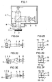
- Fig. 1 schematically shows a structure of a general optical head device.
- the device comprises a fixed optical portion A and an objective lens driving mechanism B.
- An optical recording medium C is positioned below the objective lens.
- a light beam emitted from a semiconductor laser 1 is turned into parallel beam flux by a collimator lens 2.
- the parallel beam flux passes through a beam splitter 3 to enter the objective lens 4.
- the objective lens 4 converges the parallel beam flux on the optical recording medium C.
- the position of convergence is adjusted by driving the objective lens 4 by a driving mechanism, not shown.
- the optical recording medium C comprises a transparent plate 5, tracks 6 and guide tracks 6′.
- the alternating tracks 6 and guide tracks 6′ formed of thin film of an amorphous alloy of rare earth or a transition metal constitute a recording medium.
- the light beam is controlled to be converged on a track 6 by means of the objective lens 4.
- the light beam reflected from the optical recording medium C passes through the objective lens 4 to enter the fixed optical portion A.
- the light beam from the objective lens 4 is reflected by the beam splitter 3.
- the reflected light passes through a convergent lens 8 to enter a cylindrical lens 9.
- the light beam passed through the cylindrical lens 9 is turned into beam flux having astigmatism to be converged on a photo detector 10 whose dividing line is inclined by 45° with respect to the generator of the cylindrical lens 9.
- An output from the photo detector 10 is processed by circuit means, not shown, and then it is converted into a focusing error signal.
- a focusing mechanism of the objective lens is controlled by the focusing error signal.
- Figs. 2A, 2C and 2E show optical paths of the light beam reflected from the optical recording medium C passing through the objective lens 4, the convergent lens 8 and the cylindrical lens 9 to reach the photo detector 10.
- Figs. 2B, 2D and 2F show the light beam irradiating a photo sensitive portion 20 of the photo detector 10.
- the photo sensitive portion 20 comprises for elements 10a, 10b, 10c and 10d.
- the boundaries of the four elements are two lines intersecting with each other perpendicularly. The boundaries are inclined with respect to the generator of the cylindrical lens 9 shown by an arrow in the figure.
- the center of the photo sensitive portion that is, the intersecting point of the boundaries, is positioned at midway between two focusing points generated by astigmatism, when the light beam converges on a track 6 of the optical recording medium C as shown in Fig. 2A.
- Figs. 2A and 2B show the light beam converged on a track 6.
- Figs. 2C and 2D show the light beam converged in front of the track 6.
- Figs. 2E and 2F show the light beam converged behind the track 6.
- the focusing error signal is represented as the following equation (1), where Sa, Sb, Sc and Sd represent light intensities irradiating the elements 10a, 10b, 10c and 10d of the photo sensitive portion 20, respectively.
- FES (Sa + Sc) - (Sb + Sd)
- the spot on the photo sensitive portion 20 is circular, and the light intensities irradiating the elements are the same, so that the signal FES provided in accordance with the above equation is 0.
- the spot on the photo sensitive portion 20 is an ellipse having its major axis parallel to the generator (shown by an arrow) of the cylindrical lens.
- the light intensities Sb and Sd are higher than Sa and Sc. Therefore, the signal FES has a negative value.
- the point of focus is behind the track 6 as shown in Fig.
- the spot on the photo sensitive portion 20 is an ellipse having its major axis vertical to the generator of the cylindrical lens 9. Then the light intensities Sa and Sc are higher than Sb and Sd, and the signal FES has a positive value.
- the direction of defocus depends on whether the signal FES is positive or negative, and the amount of defocus depends on the level of the signal FES. Accordingly, the objective lens driving mechanism moves the objective lens to an appropriate position in accordance with the signal FES to converge the light beam on the optical recording medium.
- Figs. 3A to 3F show this ideal state.
- Figs. 3A, 3C and 3E show positional relation between a track 6 of the optical recording medium C and a spot 11 of a light beam irradiating the optical recording medium C.
- Figs. 3B, 3D and 3F show spot shapes of the light beam irradiating the photo sensitive portion 20 of the photo detector 10. If the center of the spot 11 is off the track 6 as shown in Figs. 3A and 3E, the shape of the spot on the photo sensitive portion 20 is as shown in Figs. 3B and 3F, respectively. If the track 6 is positioned at the center of the spot 11 as shown in Fig. 3C, the shape of the spot of the light beam irradiating the photo sensitive portion 20 is circular as shown in Fig. 3D.
- the horizontal boundary X-X of the photo sensitive portion 20 is parallel to the longitudinal direction of the track 6, while the vertical boundary Y-Y is vertical to the longitudinal direction of the track 6.
- the photo sensitive portion 20 is arranged such that the optical axis of the light beam passes through the center thereof.
- the spot will be circular as shown in Fig. 3D.
- distribution of light intensity irradiating the photo sensitive portion 20 of the detector changes dependent on how much the track is off. If the optical system has no aberration, the distribution of light intensity is symmetrical about the boundary Y-Y. Therefore, even if the position of the track is off, the value of the focusing error calculated in accordance with the equation (1) is 0. Namely, imbalance of the distribution of the light intensity is offset, and the focusing error signal is not changed dependent on the deviation.
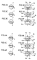
- Figs. 4A to 4F show deviation of the track and the shapes of the spot irradiating the photo sensitive portion of the photo detector when the optical system has the aberration.
- the three cases shown in Figs. 4A to 4F correspond to the three cases shown in Figs. 3A to 3F, respectively.
- the light spot irradiating the photo sensitive portion 20 of the photo detector 10 is symmetrical about the boundary Y-Y as shown in Figs. 3A to 3F. If the optical system has the aberration, the light spot is distorted as shown in Figs. 4B, 4D and 4F. The distortion is especially conspicuous when the direction of the aberration is inclined by about 45° to the longitudinal direction of the track 6. The distortion is not noticed when the direction of aberration is vertical or parallel to the longitudinal direction of the track 6. When the center of the light spot 11 is off the track 6, the shape of the light spot on the photo sensitive portion 20 is as shown in Figs. 4B and 4F, respectively.
- Figs. 4A and 4B show a waveform of a focusing error signal generated when the light spot 11 crosses the track 6.
- the abscissa represents distance between the objective lens 4 and optical recording medium C, while the ordinate represents the level of the focusing error signal.
- the optical system has an aberration, an erroneous signal is generated due to the deviation between the track 6 and the light spot 11, so that the waveform of the focusing error signal fluctuates. Especially, there is considerable fluctuation near the point of in-focus. In an ideal state where the optical system has no aberration, the waveform of the focusing error signal is a smooth curve.
- the aberration existing in the optical system makes unstable the control of focusing, and may prevents normal recording and reproducing.
- Japanese patent Laying Open JP-A-63-244416 corresponding to EP-A-0.255.305 discloses an optical information detecting device comprising an optical system having a flat glass plate for reducing influence of aberration.
- Fig. 6 shows one embodiment of the optical information detecting device.
- a flat plate 12 formed of glass having both surfaces flat is arranged between a collimator lens 2 and a semiconductor laser 1 as a light source.
- the flat plate 12 can be rotated about a optical axis 13.
- Other components of the device are the same as those shown in Fig. 1.
- This device eliminates the astigmatism remaining in the optical system by utilizing the astigmatism in accordance with the equation (2) and provides superior focusing error signal.
- the direction of the astigmatism can be adjusted by rotating the flat plate 12 about the optical axis 13.
- the magnitude of the astigmatism can be changed by the inclination ⁇ , the thickness t or the reflection index n of the parallel flat plate.
- EP-A-0 338 840 discloses a housing for accomodating a light source, a photo-detector and a monitoring photo-detector.
- the housing is closed with a hermetically sealed glass window before which a diffracting element is disposed.
- the diffracting element may be directly secured to the housing instead of the glass window to seal the interior thereby.
- An object of the present invention is to provide an optical head device capable of reducing aberration of an optical system by a mechanism which is more simple than the prior art.
- Another object of the present invention is to provide a simple system preventing degradation of a focusing error signal derived from aberration in an optical system of an optical head device.
- a further object of the present invention is to provide an optical head device which is easy to handle comprising simple mechanism for correcting the aberration provided in a housing accommodating an optical system.
- a still further object of the present invention is to provide an optical head device having a housing accommodating a light source and an optical system sealed so as to protect the light source and the optical system from dust.
- an optical head device for recording and/or reproducing information by using an optical recording medium comprising: a light source; an objective lens drivably provided for converging a light beam emitted from said light source on the optical recording medium; photo detecting means for detecting the light beam reflected by said optical recording medium; an optical system for guiding the light beam emitted from said light source to said objective lens and for guiding the light beam reflected from said optical recording medium to said photo detecting means; and an optical plate being rotatable about the optical axis of the light beam to a position reducing aberration of said objective lens and of said optical system to be set there, is characterized in that a housing is provided for accomodating said light source, said photo detecting means and said optical system, having an opening formed between said optical system and said objective lens; and that the optical plate is provided substantially perpendicular to said optical axis of the light beam passing through the opening of said housing to seal said housing.
- the optical plate is generally formed of glass.
- the optical plate may have both surfaces substantially flat or it may have one surface spherical.
- the optical plate may be provided in a holder.
- the holder holding the optical plate is rotatably attached to the housing, and by rotating the holder about the optical axis, the optical plate can be set at a position to reduce the aberration. After setting, the optical plate as well as the holder may be fixed.
- the optical system in accordance with the present invention comprises, for example, a collimator lens for turning the light beam emitted from the light source into parallel beam flux, a beam splitter passing the parallel beam flux from the collimator lens and reflecting the light reflected from the optical recording medium to the direction of the photo detector, and a lens for turning the light beam reflected by the beam splitter to a light beam having astigmatism and for converging the light beam onto the photo detector.
- An advantage of the present invention is that an optical head device capable of reducing aberration of the objective lens and of the optical system can be realized by a simple mechanism.
- the optical plate for reducing the aberration is provided to close the opening of the housing.
- the optical plate may be provided as a lid of the opening. Provision of the optical plate can be realized by a very simple structure.
- Another advantage of the present invention is that an optical head device having the housing accommodating the light source, the optical system and the photo detector sealed by the optical plate is provided.
- the sealing of the housing prevents entrance of dust into the housing. Therefore, parts of the elements in the housing, especially the optical system can be protected from dust. Thus the optical head device has longer life.
- the most important characteristic of the present invention is that the optical plate for reducing the aberration is used for sealing the housing.
- the optical head device comprises a fixed optical portion A accommodated in a housing 17, and an objective lens 4 for converging a light beam from the fixed optical portion A onto an optical recording medium C.
- the fixed optical portion A comprises a semiconductor laser 1 as a light source, a collimator lens 2, a beam splitter 3, a convergent lens 8, a cylindrical lens 9 and a photo detector 10.
- the objective lens 4 is provided movable in a driving mechanism B.
- the housing 17 has an opening 14 at a portion facing the objective lens 4.
- the opening 14 is closed by an optical plate 15 formed of a transparent glass having both surfaces flat.
- the optical plate 15 is set rotatable about the optical axis 16 of the light beam.
- the optical plate 15 is the most important part of the optical head device of the present invention.
- the light beam emitted from the semiconductor laser 1 is turned into parallel beam flux by the collimator lens 2.
- the parallel beam flux passes through the beam splitter 3 and the optical plate 15 to enter the objective lens 4.
- the objective lens 4 converges the parallel beam flux on the optical recording medium C.
- the convergence is controlled by driving the objective lens 4.
- the light beam reflected by the optical recording medium C passes through the objective lens.
- the light beam from the objective lens 4 is reflected by the beam splitter 3.
- the reflected light is converged on the photo detector 10 by the convergent lens 8 and the cylindrical lens 9.
- the system for focusing is in accordance with the principle of the above described conventional device.
- the optical plate 15 closing the opening 14 reduces the aberration of the optical system comprising the fixed optical portion A and the objective lens 4. Since the optical plate is flat, theoretically it does not generate any aberration in the parallel beam flux and it does not operate as a lens. However, actually an aberration is always generated in the optical system by the optical plate. It is very difficult to eliminate the aberration.
- the aberration is drived from small roughness of the surfaces, small warps formed during manufacturing of the optical plate and from distortion in the material.
- the optical head device of this embodiment positively utilizes the aberration generated by the optical plate.
- the aberration existing in the optical system, especially, the astigmatism is offset by the aberration generated by the optical plate. The offset of the aberration provides a superior focusing error signal.
- the direction of aberration generated by the optical plate 15 can be changed by rotating the optical plate 15 about the optical axis 16. Therefore, even if the direction of the aberration is different in different optical systems, correction can be made corresponding to the optical systems by changing the rotation angle of the optical plate.
- the focusing error signal provided by the optical head device of this embodiment is as shown in Fig. 8.
- the abscissa represents the distance between the objective lens 4 and the optical recording medium C
- the ordinate represents the level of the focusing error signal.
- the optical plate 15 for reducing the aberration has a disk shape.
- the optical plate 15 is fitted in a holder 15a.
- the holder 15a having the optical plate 15 fitted therein is fitted to a concave portion 17a of the housing 17.
- the opening 14 of the housing 17 is formed at the bottom of the concave portion 17a. Namely, the opening 14 of the housing 17 is closed by the optical plate 15 as shown in the figure.
- a notched portion 17b is formed on the housing 17 which is communicated to the concave portion 17a from a side surface.
- the driving mechanism B of the objective lens is attached to the housing 17 by means of a screw.
- the holder 15a By sticking an appropriate member through the notched portion 17b to move the holder 15a, the holder 15a can be rotated.
- the optical plate 15 is rotated together with the holder 15a. Even if the direction of aberration in the optical system and in the objective lens is different, aberrations in different directions can be reduced by using the same optical plate, by rotating the optical plate 15.
- the holder 15a may be fixed by adhesion or the like.
- the optical plate for reducing the aberration can be attached very easily by fitting the same at a concave portion of the housing by means of a holder.
- Such a structure for reducing the aberration is very simple. Since the aberration of the optical system is sufficiently reduced by this optical plate, a superior focusing error signal can be provided. Even if the directions of aberrations of the optical systems are different in different optical head devices assembled, the aberrations can be reduced by rotating the optical plate.
- the rotatably provided adjusting mechanism in the above described embodiment is very simple and manufacturing thereof is very easy compared with the prior art.
- the opening 14 of the housing 17 is sealed by the optical plate 15, so that the optical plate 15 serves to prevent entrance of dust into the housing.
- the optical system in the housing having complicated structure and having a number of exposed optical surfaces was much affected by dust, and in the worst case, recording and/or reproduction of information could not be carried out.
- entrance of dust can be prevented as the housing is sealed by the optical plate, and accordingly degradation of optical characteristics of the optical system can be prevented.
- the optical plate mainly has two functions, those are, to reduce the aberration in the optical system and to prevent entrance of dust.
- the optical plate in the above embodiment has both surfaces made flat. Such a flat plate can be manufactured relatively easily, and is ready to be practically used.
- the optical plate in accordance with the present invention may not necessarily be flat.
- An optical plate having at least one surface made spherical can be formed in accordance with the present invention.
- the optical plate can reduce the expected aberration by the function of the lens.
- the mechanism for mounting the optical plate and for adjusting rotation is not limited to that shown in the above embodiment but various modifications may be made within the scope of the invention.
Landscapes
- Physics & Mathematics (AREA)
- Optics & Photonics (AREA)
- Optical Head (AREA)
- Optical Recording Or Reproduction (AREA)
Claims (6)
- Optischer Kopf zum Aufzeichnen und/oder Wiedergeben von Information unter Verwendung eines optischen Aufzeichnungsmediums (C), mit
einer Lichtquelle (1);
einer antreibbaren Objektivlinse (4) zum Bündeln eines von der Lichtquelle (1) abgegebenen Lichtstrahls auf das optische Aufzeichnungsmedium (C);
einem Photodetektor (10) zum Erfassen des durch das optische Aufzeichnungsmedium (C) reflektierten Lichtstrahls;
einem optischen System (2, 3, 8, 9) zum Führen des von der Lichtquelle (1) abgegebenen Lichtstrahls zu der Objektivlinse (4) und zum Führen des von dem optischen Aufzeichnungsmedium (C) reflektierten Lichtstrahls zu dem Photodetektor (10); und mit
einer zum Einstellen in eine Position zum Vermindern der Aberration der Objektivlinse (4) und des optischen Systems um die optische Achse (16) des Lichtstrahls drehbaren optischen Platte (15), dadurch gekennzeichnet, daß
ein Gehäuse (17) zum Aufnehmen der Lichtquelle (1), des Photodetektors (10) und des optischen Systems (2, 3, 8, 9) vorgesehen ist, mit einer zwischen dem optischen System und der Objektivlinse vorhanden Öffnung (14); und daß
die optische Platte (15) im wesentlichen senkrecht zu der optischen Achse (16) des durch die Öffnung (14) des Gehäuses (17) gelangenden Lichtstrahls steht, um das Gehäuse (17) abzudichten. - Optischer Kopf nach Anspruch 1, dadurch gekennzeichnet, daß die optische Platte (15) aus Glas besteht.
- Optischer Kopf nach Anspruch 1, dadurch gekennzeichnet, daß beide Oberflächen der optischen Platte (15) im wesentlichen flach sind.
- Optischer Kopf nach Anspruch 1, dadurch gekennzeichnet, daß mindestens eine Oberfläche der optischen Platte (15) sphärisch ausgebildet ist.
- Optischer Kopf nach Anspruch 1, dadurch gekennzeichnet, daß die optische Platte (15) in einem drehbar in dem Gehäuse (17) gehaltenen Träger (15a) getragen wird, bevor durch Drehen des Trägers (15a) die Position der optischen Platte zum Vermindern der Aberration eingestellt wird.
- Optischer Kopf nach Anspruch 1, dadurch gekennzeichnet, daß das optische System aufweist
eine Kollimatorlinse (2) zum Wandeln des von der Lichtquelle (1) abgegebenen Lichtstrahls in einen parallelen Strahlfluß, einen Strahlteiler (3) zum Durchlassen des parallelen Strahls von der Kollimatorlinse (2) und zum Reflektieren des von dem optischen Aufzeichnungsmedium (C) reflektierten Lichtstrahls in Richtung des Photodetektors (10), sowie eine Linse (8) zum Bündeln des von dem Strahlteiler reflektierten Lichtstrahls auf den Photodetektor (10).
Applications Claiming Priority (2)
| Application Number | Priority Date | Filing Date | Title |
|---|---|---|---|
| JP12987/90 | 1990-01-22 | ||
| JP2012987A JP2655923B2 (ja) | 1990-01-22 | 1990-01-22 | 光ヘッド装置 |
Publications (3)
| Publication Number | Publication Date |
|---|---|
| EP0439100A2 EP0439100A2 (de) | 1991-07-31 |
| EP0439100A3 EP0439100A3 (en) | 1992-01-15 |
| EP0439100B1 true EP0439100B1 (de) | 1995-12-27 |
Family
ID=11820559
Family Applications (1)
| Application Number | Title | Priority Date | Filing Date |
|---|---|---|---|
| EP91100703A Expired - Lifetime EP0439100B1 (de) | 1990-01-22 | 1991-01-21 | Optische Kopfanordnung |
Country Status (4)
| Country | Link |
|---|---|
| US (1) | US5270997A (de) |
| EP (1) | EP0439100B1 (de) |
| JP (1) | JP2655923B2 (de) |
| DE (1) | DE69115721T2 (de) |
Families Citing this family (9)
| Publication number | Priority date | Publication date | Assignee | Title |
|---|---|---|---|---|
| USRE37185E1 (en) * | 1990-04-20 | 2001-05-22 | Matsushita Electric Industrial Co., Ltd. | Optical head |
| US5148421A (en) * | 1990-04-20 | 1992-09-15 | Matsushita Electric Industrial Co., Ltd. | Optical head |
| DE4135011C2 (de) * | 1990-10-23 | 1996-06-05 | Asahi Optical Co Ltd | Bildplattengerät |
| JP2807589B2 (ja) * | 1992-02-13 | 1998-10-08 | シャープ株式会社 | 光源ユニット及び該光源ユニットを使用した光学ヘッド |
| US5777961A (en) * | 1994-06-27 | 1998-07-07 | Nec Corporation | Astigmatic difference correcting method for optical head and apparatus therefor |
| JPH10172243A (ja) * | 1996-12-11 | 1998-06-26 | Sony Corp | 円盤状記録媒体および円盤状記録媒体再生装置 |
| JPH10199005A (ja) * | 1996-12-26 | 1998-07-31 | Sony Corp | 光学ピックアップ装置 |
| AU8160198A (en) | 1997-07-16 | 1999-02-10 | Rockshox, Inc. | Bicycle fork suspension having a single primary compression spring system |
| US7059868B1 (en) | 2000-03-07 | 2006-06-13 | Western Digital (Fremont), Inc. | Connection of trace circuitry in a computer disk drive system |
Family Cites Families (9)
| Publication number | Priority date | Publication date | Assignee | Title |
|---|---|---|---|---|
| NL8004892A (nl) * | 1980-08-29 | 1982-04-01 | Philips Nv | Inrichting voor het verwerken van optische informatie en werkwijze voor het vervaardigen van een coma-correctieplaat zoals toegepast in een dergelijke inrichting. |
| DE3575805D1 (de) * | 1984-10-11 | 1990-03-08 | Hitachi Ltd | Halterung fuer optische linse. |
| NL8502802A (nl) * | 1985-10-14 | 1987-05-04 | Philips Nv | Inrichting voor het uitlezen en/of inschrijven van een optische spoorvormige informatiestruktuur. |
| JPH0648543B2 (ja) * | 1985-12-04 | 1994-06-22 | 三菱電機株式会社 | 光学ヘツド装置 |
| CA1319194C (en) * | 1986-07-28 | 1993-06-15 | Hideaki Satou | Focusing error detector and optical data detecting device incorporating the focusing error detector |
| JPS63244416A (ja) * | 1987-03-31 | 1988-10-11 | Sharp Corp | 光情報検出装置 |
| JP2633535B2 (ja) * | 1986-09-18 | 1997-07-23 | ソニー株式会社 | 光学ピツクアツプ装置 |
| JPH0770065B2 (ja) * | 1988-04-20 | 1995-07-31 | シャープ株式会社 | 光ピックアップ装置 |
| US5023858A (en) * | 1989-02-28 | 1991-06-11 | Ricoh Company, Ltd. | Separation type optical pickup device |
-
1990
- 1990-01-22 JP JP2012987A patent/JP2655923B2/ja not_active Expired - Lifetime
-
1991
- 1991-01-15 US US07/641,261 patent/US5270997A/en not_active Expired - Lifetime
- 1991-01-21 EP EP91100703A patent/EP0439100B1/de not_active Expired - Lifetime
- 1991-01-21 DE DE69115721T patent/DE69115721T2/de not_active Expired - Lifetime
Also Published As
| Publication number | Publication date |
|---|---|
| EP0439100A2 (de) | 1991-07-31 |
| EP0439100A3 (en) | 1992-01-15 |
| DE69115721D1 (de) | 1996-02-08 |
| JPH03216823A (ja) | 1991-09-24 |
| DE69115721T2 (de) | 1997-02-06 |
| US5270997A (en) | 1993-12-14 |
| JP2655923B2 (ja) | 1997-09-24 |
Similar Documents
| Publication | Publication Date | Title |
|---|---|---|
| EP0351953B1 (de) | Optischer Kopf mit Kippkorrekturservomechanismus | |
| US5513158A (en) | Optical disk pickup device with focusing correction by electrostriction | |
| US6498330B1 (en) | Spherical aberration detector and optical pickup device | |
| EP0199565B1 (de) | Halbleiterlaservorrichtung für optischen Kopf | |
| EP0198655B1 (de) | Optische Köpfe | |
| US20060018233A1 (en) | Read write device for optical memory and method therefore | |
| US5638353A (en) | Optical head device | |
| EP0777221B1 (de) | Optischer Abtastkopf zur Wiedergabe und Aufzeichnung für Plattendicke unterschiedlicher Stärke | |
| EP0184750B1 (de) | Optische Aufnahme- und Wiedergabevorrichtung | |
| EP0439100B1 (de) | Optische Kopfanordnung | |
| CA1319194C (en) | Focusing error detector and optical data detecting device incorporating the focusing error detector | |
| US6751175B1 (en) | Aberration correcting device and optical pickup apparatus using the same | |
| US5018127A (en) | Light emitting apparatus having a plurality of light emitting points | |
| JP3260426B2 (ja) | 光学式ピックアップ装置 | |
| US6188528B1 (en) | Optical lens, and optical pickup and optical disc apparatus using such lens | |
| KR100486818B1 (ko) | 다른구조를갖는광기록매체에기록및/또는이로부터판독하기위한장치 | |
| US5761176A (en) | Optical head device with optically variable aperture for disks with different thicknesses | |
| JPH06324281A (ja) | 光ピックアップ装置 | |
| JP2605636B2 (ja) | 光ヘッドの非点隔差補正方法および装置 | |
| EP1554722B1 (de) | Optische scanning einrichtung mit neigungsdetektion | |
| US6055221A (en) | Galvano-mirror optical head capable of adjusting relative positions | |
| US7274649B2 (en) | Holographic ROM system | |
| JPH0935319A (ja) | 光情報記録装置及び光学装置、並びに収差調整方法 | |
| JPH03266224A (ja) | 光ピックアップ | |
| JP2000222767A (ja) | 光学ヘッド |
Legal Events
| Date | Code | Title | Description |
|---|---|---|---|
| PUAI | Public reference made under article 153(3) epc to a published international application that has entered the european phase |
Free format text: ORIGINAL CODE: 0009012 |
|
| AK | Designated contracting states |
Kind code of ref document: A2 Designated state(s): DE GB |
|
| PUAL | Search report despatched |
Free format text: ORIGINAL CODE: 0009013 |
|
| AK | Designated contracting states |
Kind code of ref document: A3 Designated state(s): DE GB |
|
| 17P | Request for examination filed |
Effective date: 19920407 |
|
| 17Q | First examination report despatched |
Effective date: 19940629 |
|
| GRAA | (expected) grant |
Free format text: ORIGINAL CODE: 0009210 |
|
| AK | Designated contracting states |
Kind code of ref document: B1 Designated state(s): DE GB |
|
| REF | Corresponds to: |
Ref document number: 69115721 Country of ref document: DE Date of ref document: 19960208 |
|
| PLBE | No opposition filed within time limit |
Free format text: ORIGINAL CODE: 0009261 |
|
| STAA | Information on the status of an ep patent application or granted ep patent |
Free format text: STATUS: NO OPPOSITION FILED WITHIN TIME LIMIT |
|
| 26N | No opposition filed | ||
| REG | Reference to a national code |
Ref country code: GB Ref legal event code: IF02 |
|
| PGFP | Annual fee paid to national office [announced via postgrant information from national office to epo] |
Ref country code: GB Payment date: 20100120 Year of fee payment: 20 Ref country code: DE Payment date: 20100114 Year of fee payment: 20 |
|
| REG | Reference to a national code |
Ref country code: GB Ref legal event code: PE20 Expiry date: 20110120 |
|
| PG25 | Lapsed in a contracting state [announced via postgrant information from national office to epo] |
Ref country code: GB Free format text: LAPSE BECAUSE OF EXPIRATION OF PROTECTION Effective date: 20110120 |
|
| PG25 | Lapsed in a contracting state [announced via postgrant information from national office to epo] |
Ref country code: DE Free format text: LAPSE BECAUSE OF EXPIRATION OF PROTECTION Effective date: 20110121 |