EP0439663B1 - Procédé de commande d'un laminoir continu à plusieurs cages - Google Patents
Procédé de commande d'un laminoir continu à plusieurs cages Download PDFInfo
- Publication number
- EP0439663B1 EP0439663B1 EP90102109A EP90102109A EP0439663B1 EP 0439663 B1 EP0439663 B1 EP 0439663B1 EP 90102109 A EP90102109 A EP 90102109A EP 90102109 A EP90102109 A EP 90102109A EP 0439663 B1 EP0439663 B1 EP 0439663B1
- Authority
- EP
- European Patent Office
- Prior art keywords
- rolling
- mill
- tension
- value
- values
- Prior art date
- Legal status (The legal status is an assumption and is not a legal conclusion. Google has not performed a legal analysis and makes no representation as to the accuracy of the status listed.)
- Revoked
Links
- 238000005096 rolling process Methods 0.000 title claims abstract description 26
- 238000000034 method Methods 0.000 title claims description 10
- 239000000463 material Substances 0.000 claims description 4
- 229910000831 Steel Inorganic materials 0.000 claims description 2
- 239000010959 steel Substances 0.000 claims description 2
- 230000005540 biological transmission Effects 0.000 claims 1
- 230000015654 memory Effects 0.000 abstract description 3
- 238000010079 rubber tapping Methods 0.000 description 5
- 230000001914 calming effect Effects 0.000 description 4
- 230000006870 function Effects 0.000 description 2
- 238000006243 chemical reaction Methods 0.000 description 1
- 230000001276 controlling effect Effects 0.000 description 1
- 230000001419 dependent effect Effects 0.000 description 1
- 238000010586 diagram Methods 0.000 description 1
- 230000001105 regulatory effect Effects 0.000 description 1
Images

Classifications
-
- B—PERFORMING OPERATIONS; TRANSPORTING
- B21—MECHANICAL METAL-WORKING WITHOUT ESSENTIALLY REMOVING MATERIAL; PUNCHING METAL
- B21B—ROLLING OF METAL
- B21B37/00—Control devices or methods specially adapted for metal-rolling mills or the work produced thereby
- B21B37/48—Tension control; Compression control
- B21B37/52—Tension control; Compression control by drive motor control
Definitions
- the invention relates to a method for controlling a continuous, multi-stand rolling mill, in particular a steel mill, whereby, depending on the armature currents of the rolling motors in the individual stands, before and after tapping the rolling stock in the subsequent stands, additional speed setpoints are generated according to a predetermined calculation rule, and the The speeds of the individual stands are controlled via the additional speed setpoints in the sense of a minimum tension control.
- Such a method is known from AEG-Mitannonen, 56, (1966), No. 1, pages 54-57, or Technische Mitteilungen AEG-TELEFUNKEN, 66 (1976), No. 6, pages 255-261, under the name minimum tension control .
- a scanning system can also be provided which, in the time between the tapping of two successive stands, only executes a single actuating step for adapting the speed to the change in the motor current before and after tapping. This should enable a draft and pressure-free rolling. With a single setting step for speed adjustment between two successive stands, however, a more or less high residual error is to be expected, which is why several successive setting steps between two taps are aimed for. However, high throughput speeds prevent this.
- the additional speed setpoints are additionally generated as a function of a tensile current setpoint, which is predetermined as empirical value in the form of a specific setpoint tension in the rolling stock.
- the predetermined tensile tension prevents the occurrence of compressive forces in the rolling stock.
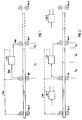
- the individual roll stands are denoted by 1 and an index.
- the symbolically represented rolling stock passes through one after the other in the direction of the arrow.
- the minimum tension control by the control device 2 is shown in this example between the roll stands 1 m and 1 m + 1 .
- the armature current J A1 and J A2 is measured on the roll stand 1 m and is supplied to the control device 2 via the signal path 12.
- the additional speed setpoint n * Z % determined and given to the scaffold 1 m + 1 via signal path 13.
- the lead time of the Rolled material between the stands 1 m and 1 m + 1 is divided into a calming time t A1 for regulating the tapping in the stand 1 m and a safety time t S1 , the setpoint change for the following stand 1 m + 1 being determined after the calming time t A1 .
- the control direction can also run according to the dashed line 14, that is to say in the opposite direction.
- the individual stands are adjusted at high rolling stock speeds, for example in the case of rolling head times from stand to stand under one to two seconds, in such a way that the additional speed setpoint n * Z % is not changed until the next rolling pass.
- the control cycle therefore extends from rod to rod.
- FIG. 2 in which the rolling stands are denoted by 1 n , the arrangement and mode of operation of the control device 2 is in principle corresponding to FIG. 1, but here the next following stand 1 n + 1 is already influenced during the same pass through the rolling stock.
- the tapping of stand 1 n is first corrected in a calming time t A1
- the current value J A2 is stored in control device 2 n-1 and an adjustment is carried out.
- the resulting renewed load current is corrected in the calming time t B1 and the current J A1 is stored for the calculations of the minimum draft control 2 n .
- a safety time t S1 is also provided here, which avoids a time overlap.
- 2 also designates the control device according to the invention, in the computer part 2 'of which a rolling path replica is included as a model. Furthermore, the control device 2 has a setpoint setting part 2 ′′ in which the speed setpoint n * is formed, the signal of which is designated by 11. 2 '''denotes the parameter input unit of the control device 2, to which signals from a keyboard or a monitor are applied via the signal path 8. The replica of the rolling stock is entered via various photo cells etc. via signal path 9, the respective position of the rolling stock.
- the computer 2 can enter the armature currents J A1 , J A2 , which are input via the preferably six-pole Butterworth filter 10, divided into the closed state and the tensile state, into the memories 3 and 4 in a position-related manner.
- the signals of the armature currents J A1 , J A2 for the draft-free and the tensile state reach the difference-forming device 5, which also contains the tension current setpoint ⁇ J * A , an empirical value that is dependent on the speed and rolling program is entered from parameter input 2 '''.
- the traction current error is determined from this data and, together with the empirical value K E, fed to the multiplier 6, in which the speed setpoint n * Z % is formed.
- the transfer unit which ensures that the signal is formed as a function of the speed in a rolling gap or when the rod is running as shown in FIG. 2 as an adjustment command via the setpoint adjuster 2 ′′ as setpoint n *, is designated by 7.
- the units 3, 4, 5, 6 and 7 together form the computing part of the control device 2 for the continuous determination and timely delivery of the speed setpoint n *.
Landscapes
- Engineering & Computer Science (AREA)
- Mechanical Engineering (AREA)
- Control Of Metal Rolling (AREA)
- Metal Rolling (AREA)
- Control Of Heat Treatment Processes (AREA)
- Machines For Manufacturing Corrugated Board In Mechanical Paper-Making Processes (AREA)
- Feedback Control In General (AREA)
- Control Of Velocity Or Acceleration (AREA)
- Electric Propulsion And Braking For Vehicles (AREA)
Claims (6)
- Procédé pour commander un laminoir continu à plusieurs cages, notamment un laminoir pour barres, selon lequel, en fonction des courants d'induit (JA1, JA2) des moteurs du laminoir, des valeurs de consigne supplémentaires de la vitesse de rotation (n*Z%) sont produites, selon une règle de calcul prédéterminée, dans les différentes cages (m;n) en amont et en aval de l'insertion du produit à laminer dans les cages respectives suivantes (m+1;n+1), et selon lequel les vitesses de rotation des différentes cages sont commandées par l'intermédiaire des valeurs de consigne supplémentaires de la vitesse de rotation (n*Z%), dans le sens du réglage de la traction minimale,
caractérisé par le fait que les valeurs de consigne supplémentaires de la vitesse de rotation (n*Z%) sont produites en supplément en fonction d'une valeur de consigne (D J*A) du courant de tirage, qui est prédéterminée en tant que valeur empirique sous la forme d'une traction de consigne spécifique (σ*AZ) dans le produit à laminer. - Procédé suivant la revendication 1, caractérisé par le fait que les valeurs de consigne supplémentaires de la vitesse de rotation (n*Z%) sont formées selon la règle de calcul

- Procédé suivant la revendication 2, caractérisé par le fait que la valeur empirique KE est formée sous la forme d'une variation en pourcentage de la vitesse de rotation pour chaque N/mm².
- Procédé suivant la revendication 2 ou 3, caractérisé par le fait que la valeur empirique KE est à nouveau prédéterminée après les déplacements de commande, qui dépassent des valeurs limites.
- Procédé suivant l'une des revendications précédentes, caractérisé par le fait que la valeur de consigne (Δ JA*) du courant de tirage est formée conformément à la relation

- Procédé suivant l'une des revendications précédentes, caractérisé par le fait que la valeur de consigne (Δ JA*) du courant de tirage est déterminée sur la base de tolérances de valeurs réelles de traction, sur plusieurs passes non réglées.
Priority Applications (6)
| Application Number | Priority Date | Filing Date | Title |
|---|---|---|---|
| ES199090102109T ES2046545T3 (es) | 1990-02-02 | 1990-02-02 | Instalacion de control para un tren de laminacion continuo de varios bastidores. |
| EP90102109A EP0439663B1 (fr) | 1990-02-02 | 1990-02-02 | Procédé de commande d'un laminoir continu à plusieurs cages |
| AT90102109T ATE97838T1 (de) | 1990-02-02 | 1990-02-02 | Verfahren zum steuern einer kontinuierlichen, mehrgeruestigen walzstrasse. |
| DE90102109T DE59003705D1 (de) | 1990-02-02 | 1990-02-02 | Verfahren zum Steuern einer kontinuierlichen, mehrgerüstigen Walzstrasse. |
| FI910011A FI93805C (fi) | 1990-02-02 | 1991-01-02 | Menetelmä jatkuvatoimisen, useamman valssituolin käsittävän valssauslinjan ohjaamiseksi |
| JP3032293A JPH04220109A (ja) | 1990-02-02 | 1991-01-30 | 複数スタンド連続圧延ライン用制御装置 |
Applications Claiming Priority (1)
| Application Number | Priority Date | Filing Date | Title |
|---|---|---|---|
| EP90102109A EP0439663B1 (fr) | 1990-02-02 | 1990-02-02 | Procédé de commande d'un laminoir continu à plusieurs cages |
Publications (2)
| Publication Number | Publication Date |
|---|---|
| EP0439663A1 EP0439663A1 (fr) | 1991-08-07 |
| EP0439663B1 true EP0439663B1 (fr) | 1993-12-01 |
Family
ID=8203579
Family Applications (1)
| Application Number | Title | Priority Date | Filing Date |
|---|---|---|---|
| EP90102109A Revoked EP0439663B1 (fr) | 1990-02-02 | 1990-02-02 | Procédé de commande d'un laminoir continu à plusieurs cages |
Country Status (6)
| Country | Link |
|---|---|
| EP (1) | EP0439663B1 (fr) |
| JP (1) | JPH04220109A (fr) |
| AT (1) | ATE97838T1 (fr) |
| DE (1) | DE59003705D1 (fr) |
| ES (1) | ES2046545T3 (fr) |
| FI (1) | FI93805C (fr) |
Families Citing this family (1)
| Publication number | Priority date | Publication date | Assignee | Title |
|---|---|---|---|---|
| DE10137246A1 (de) * | 2001-07-30 | 2003-02-20 | Siemens Ag | Walzstraße |
Family Cites Families (6)
| Publication number | Priority date | Publication date | Assignee | Title |
|---|---|---|---|---|
| AU475854B2 (en) * | 1972-09-06 | 1976-09-02 | Mitsubishi Electric Corporation | System for controlling rolling mills |
| JPS595364B2 (ja) * | 1977-01-07 | 1984-02-04 | 株式会社日立製作所 | 張力制御方法 |
| FR2399883A1 (fr) * | 1977-08-08 | 1979-03-09 | Siderurgie Fse Inst Rech | Procede de prereglage d'un train continu a cages tandem pour le laminage a chaud de produits metalliques |
| DE2834102C2 (de) * | 1978-08-03 | 1982-11-18 | Siemens AG, 1000 Berlin und 8000 München | Vorrichtung zur Regelung der im Walzgut übertragenenZugkraft in einer m Gerüste enthaltenden Walzstraße |
| EP0130231B1 (fr) * | 1983-07-04 | 1987-01-21 | Siemens Aktiengesellschaft | Arrangement de circuits pour la régulation de la force de traction transmise entre les cages de cylindres d'un train de laminoir à cages multiples |
| DE3821990A1 (de) * | 1988-06-30 | 1990-01-11 | Schloemann Siemag Ag | Regelung fuer profilstrassen |
-
1990
- 1990-02-02 AT AT90102109T patent/ATE97838T1/de not_active IP Right Cessation
- 1990-02-02 EP EP90102109A patent/EP0439663B1/fr not_active Revoked
- 1990-02-02 ES ES199090102109T patent/ES2046545T3/es not_active Expired - Lifetime
- 1990-02-02 DE DE90102109T patent/DE59003705D1/de not_active Revoked
-
1991
- 1991-01-02 FI FI910011A patent/FI93805C/fi active
- 1991-01-30 JP JP3032293A patent/JPH04220109A/ja not_active Withdrawn
Also Published As
| Publication number | Publication date |
|---|---|
| ATE97838T1 (de) | 1993-12-15 |
| DE59003705D1 (de) | 1994-01-13 |
| ES2046545T3 (es) | 1994-02-01 |
| FI93805B (fi) | 1995-02-28 |
| FI910011A0 (fi) | 1991-01-02 |
| EP0439663A1 (fr) | 1991-08-07 |
| FI93805C (fi) | 1995-06-12 |
| JPH04220109A (ja) | 1992-08-11 |
| FI910011L (fi) | 1991-08-03 |
Similar Documents
| Publication | Publication Date | Title |
|---|---|---|
| DE102010013387B4 (de) | Steuervorrichtung und -verfahren für ein Walzwerk | |
| DE4105321A1 (de) | Regelung eines warm- und/oder kaltwalzprozesses | |
| EP2603337B1 (fr) | Procédé de production de laminés à l'aide d'une installation combinée de laminage direct, dispositif de commande et/ou de régulation pour une installation combinée de laminage direct, et installation combinée de laminage direct | |
| DE4125095C2 (de) | Motorregelsystem | |
| DE10047381A1 (de) | Verfahren und Vorrichtung zum Betreiben einer Anlage der Grundstoffindustrie | |
| DE69607781T2 (de) | Warmbandwalzanlage | |
| EP2621645B1 (fr) | Procédé de commande d'un train de laminoir tandem, dispositif de commande et/ou de régulation pour un train de laminoir tandem, code de programme lisible par machine, support de stockage et train de laminoir tandem | |
| WO2004080628A1 (fr) | Installation de coulee continue et de laminage pour produire un feuillard d'acier | |
| EP0972581A2 (fr) | Procédé de laminage pour produits en forme de barres, notamment d'acier en barres ou de fils | |
| EP1314491B1 (fr) | Mode d'opération d'un laminoir étireur-réducteur et laminoir étireur-réducteur | |
| DE2713053A1 (de) | Verfahren zum regeln der spannung zwischen den walzgeruesten in einer walzstrasse | |
| DE1919815A1 (de) | Verfahren und Vorrichtung zum kontinuierlichen Walzen duenner Baender | |
| EP0008037A1 (fr) | Dispositif de commande de la tension dans un laminoir continu | |
| EP2268427B1 (fr) | Procédé d'exploitation pour un train de laminoir à froid avec dynamique améliorée | |
| EP0348777B1 (fr) | Commande pour trains de laminoirs à profilés | |
| AT225655B (de) | Mehrständerwalzwerk | |
| DE4232685A1 (de) | Vorrichtung zum Regeln der Drehzahlen der Walzen eines Walzwerkes | |
| EP0775537A2 (fr) | Procédé pour la régulation de la section transversale d'un produit laminé | |
| DE19881709B4 (de) | Verfahren zum Schneiden eines Metallbandes, das aus einer Warmwalzstraße ausläuft, und Vorrichtung zur Durchführung des Verfahrens | |
| DE3317635A1 (de) | Warmwalzverfahren | |
| DE102022208499A1 (de) | Verfahren und Computerprogrammprodukt zum Betreiben einer Gieß-Walzanlage | |
| DE3121851C2 (de) | Walzanlage mit mehreren, hintereinander angeordneten Gerüsten zum kontinuierlichen Walzen von Knüppeln | |
| EP1669141B1 (fr) | Procédé pour le réglage de la section des fils sortant d'un train de laminage de fil et train de laminage de fil | |
| EP0439663A1 (fr) | Procédé de commande d'un laminoir continu à plusieurs cages | |
| DE10126220C2 (de) | Verfahren und Vorrichtung zum Betreiben einer Drahtwalzstraße |
Legal Events
| Date | Code | Title | Description |
|---|---|---|---|
| PUAI | Public reference made under article 153(3) epc to a published international application that has entered the european phase |
Free format text: ORIGINAL CODE: 0009012 |
|
| 17P | Request for examination filed |
Effective date: 19901220 |
|
| AK | Designated contracting states |
Kind code of ref document: A1 Designated state(s): AT BE CH DE ES FR GB GR IT LI LU NL SE |
|
| 17Q | First examination report despatched |
Effective date: 19920406 |
|
| GRAA | (expected) grant |
Free format text: ORIGINAL CODE: 0009210 |
|
| AK | Designated contracting states |
Kind code of ref document: B1 Designated state(s): AT BE CH DE ES FR GB GR IT LI LU NL SE |
|
| PG25 | Lapsed in a contracting state [announced via postgrant information from national office to epo] |
Ref country code: SE Effective date: 19931201 Ref country code: NL Effective date: 19931201 |
|
| REF | Corresponds to: |
Ref document number: 97838 Country of ref document: AT Date of ref document: 19931215 Kind code of ref document: T |
|
| REF | Corresponds to: |
Ref document number: 59003705 Country of ref document: DE Date of ref document: 19940113 |
|
| REG | Reference to a national code |
Ref country code: ES Ref legal event code: FG2A Ref document number: 2046545 Country of ref document: ES Kind code of ref document: T3 |
|
| PG25 | Lapsed in a contracting state [announced via postgrant information from national office to epo] |
Ref country code: AT Effective date: 19940202 |
|
| ITF | It: translation for a ep patent filed | ||
| PG25 | Lapsed in a contracting state [announced via postgrant information from national office to epo] |
Ref country code: LU Free format text: LAPSE BECAUSE OF NON-PAYMENT OF DUE FEES Effective date: 19940228 Ref country code: LI Free format text: LAPSE BECAUSE OF NON-PAYMENT OF DUE FEES Effective date: 19940228 Ref country code: CH Free format text: LAPSE BECAUSE OF NON-PAYMENT OF DUE FEES Effective date: 19940228 |
|
| PG25 | Lapsed in a contracting state [announced via postgrant information from national office to epo] |
Ref country code: GR Free format text: LAPSE BECAUSE OF FAILURE TO SUBMIT A TRANSLATION OF THE DESCRIPTION OR TO PAY THE FEE WITHIN THE PRESCRIBED TIME-LIMIT Effective date: 19940304 |
|
| ET | Fr: translation filed | ||
| GBT | Gb: translation of ep patent filed (gb section 77(6)(a)/1977) |
Effective date: 19940225 |
|
| NLV1 | Nl: lapsed or annulled due to failure to fulfill the requirements of art. 29p and 29m of the patents act | ||
| PLBI | Opposition filed |
Free format text: ORIGINAL CODE: 0009260 |
|
| PLBI | Opposition filed |
Free format text: ORIGINAL CODE: 0009260 |
|
| 26 | Opposition filed |
Opponent name: ELPRO AG Effective date: 19940701 |
|
| 26 | Opposition filed |
Opponent name: AEG AKTIENGESELLSCHAFT Effective date: 19940817 Opponent name: ELPRO AG Effective date: 19940701 |
|
| REG | Reference to a national code |
Ref country code: CH Ref legal event code: PL |
|
| RDAH | Patent revoked |
Free format text: ORIGINAL CODE: EPIDOS REVO |
|
| APAC | Appeal dossier modified |
Free format text: ORIGINAL CODE: EPIDOS NOAPO |
|
| APAE | Appeal reference modified |
Free format text: ORIGINAL CODE: EPIDOS REFNO |
|
| APCC | Communication from the board of appeal sent |
Free format text: ORIGINAL CODE: EPIDOS OBAPO |
|
| PLAB | Opposition data, opponent's data or that of the opponent's representative modified |
Free format text: ORIGINAL CODE: 0009299OPPO |
|
| R26 | Opposition filed (corrected) |
Opponent name: ELPRO AG * 940817 AEG AKTIENGESELLSCHAFT Effective date: 19940701 |
|
| PLBQ | Unpublished change to opponent data |
Free format text: ORIGINAL CODE: EPIDOS OPPO |
|
| PLAB | Opposition data, opponent's data or that of the opponent's representative modified |
Free format text: ORIGINAL CODE: 0009299OPPO |
|
| PGFP | Annual fee paid to national office [announced via postgrant information from national office to epo] |
Ref country code: GB Payment date: 19980113 Year of fee payment: 9 |
|
| R26 | Opposition filed (corrected) |
Opponent name: ELPRO AG * 940817 EHG ELEKTROHOLDING GMBH Effective date: 19940701 |
|
| PGFP | Annual fee paid to national office [announced via postgrant information from national office to epo] |
Ref country code: ES Payment date: 19980211 Year of fee payment: 9 |
|
| PGFP | Annual fee paid to national office [announced via postgrant information from national office to epo] |
Ref country code: BE Payment date: 19980218 Year of fee payment: 9 |
|
| PGFP | Annual fee paid to national office [announced via postgrant information from national office to epo] |
Ref country code: FR Payment date: 19980223 Year of fee payment: 9 |
|
| PGFP | Annual fee paid to national office [announced via postgrant information from national office to epo] |
Ref country code: DE Payment date: 19980420 Year of fee payment: 9 |
|
| PLAB | Opposition data, opponent's data or that of the opponent's representative modified |
Free format text: ORIGINAL CODE: 0009299OPPO |
|
| R26 | Opposition filed (corrected) |
Opponent name: GE INDUSTRIAL SYSTEMS GMBH * 940817 EHG ELEKTROHOL Effective date: 19940701 |
|
| APCC | Communication from the board of appeal sent |
Free format text: ORIGINAL CODE: EPIDOS OBAPO |
|
| APAC | Appeal dossier modified |
Free format text: ORIGINAL CODE: EPIDOS NOAPO |
|
| RDAG | Patent revoked |
Free format text: ORIGINAL CODE: 0009271 |
|
| STAA | Information on the status of an ep patent application or granted ep patent |
Free format text: STATUS: PATENT REVOKED |
|
| 27W | Patent revoked |
Effective date: 19981125 |
|
| GBPR | Gb: patent revoked under art. 102 of the ep convention designating the uk as contracting state |
Free format text: 981125 |
|
| APAH | Appeal reference modified |
Free format text: ORIGINAL CODE: EPIDOSCREFNO |