EP0439788A2 - Composition de verre et méthode de fabrication d'une plaque de microcanaux à haute performance - Google Patents
Composition de verre et méthode de fabrication d'une plaque de microcanaux à haute performance Download PDFInfo
- Publication number
- EP0439788A2 EP0439788A2 EP90124783A EP90124783A EP0439788A2 EP 0439788 A2 EP0439788 A2 EP 0439788A2 EP 90124783 A EP90124783 A EP 90124783A EP 90124783 A EP90124783 A EP 90124783A EP 0439788 A2 EP0439788 A2 EP 0439788A2
- Authority
- EP
- European Patent Office
- Prior art keywords
- glass
- mole percent
- present
- composition
- glass composition
- Prior art date
- Legal status (The legal status is an assumption and is not a legal conclusion. Google has not performed a legal analysis and makes no representation as to the accuracy of the status listed.)
- Granted
Links
- 239000011521 glass Substances 0.000 title claims abstract description 258
- 239000000203 mixture Substances 0.000 title claims abstract description 106
- 238000000034 method Methods 0.000 title claims abstract description 17
- 238000004519 manufacturing process Methods 0.000 title claims abstract description 14
- 230000009466 transformation Effects 0.000 claims abstract description 7
- 239000005373 porous glass Substances 0.000 claims abstract description 6
- QVQLCTNNEUAWMS-UHFFFAOYSA-N barium oxide Inorganic materials [Ba]=O QVQLCTNNEUAWMS-UHFFFAOYSA-N 0.000 claims description 15
- 229910001953 rubidium(I) oxide Inorganic materials 0.000 claims description 12
- 238000007493 shaping process Methods 0.000 claims description 12
- VYPSYNLAJGMNEJ-UHFFFAOYSA-N silicon dioxide Inorganic materials O=[Si]=O VYPSYNLAJGMNEJ-UHFFFAOYSA-N 0.000 claims description 12
- KOPBYBDAPCDYFK-UHFFFAOYSA-N Cs2O Inorganic materials [O-2].[Cs+].[Cs+] KOPBYBDAPCDYFK-UHFFFAOYSA-N 0.000 claims description 10
- GOLCXWYRSKYTSP-UHFFFAOYSA-N arsenic trioxide Inorganic materials O1[As]2O[As]1O2 GOLCXWYRSKYTSP-UHFFFAOYSA-N 0.000 claims description 10
- ADCOVFLJGNWWNZ-UHFFFAOYSA-N antimony trioxide Inorganic materials O=[Sb]O[Sb]=O ADCOVFLJGNWWNZ-UHFFFAOYSA-N 0.000 claims description 8
- 238000000137 annealing Methods 0.000 claims description 4
- 150000001875 compounds Chemical class 0.000 claims description 4
- FZLIPJUXYLNCLC-UHFFFAOYSA-N lanthanum atom Chemical group [La] FZLIPJUXYLNCLC-UHFFFAOYSA-N 0.000 claims description 3
- 230000004323 axial length Effects 0.000 claims description 2
- 239000000156 glass melt Substances 0.000 claims description 2
- 239000000835 fiber Substances 0.000 description 13
- 238000005530 etching Methods 0.000 description 9
- 239000003365 glass fiber Substances 0.000 description 9
- HTUMBQDCCIXGCV-UHFFFAOYSA-N lead oxide Chemical compound [O-2].[Pb+2] HTUMBQDCCIXGCV-UHFFFAOYSA-N 0.000 description 5
- 239000000463 material Substances 0.000 description 5
- TYIXMATWDRGMPF-UHFFFAOYSA-N dibismuth;oxygen(2-) Chemical compound [O-2].[O-2].[O-2].[Bi+3].[Bi+3] TYIXMATWDRGMPF-UHFFFAOYSA-N 0.000 description 4
- 238000010438 heat treatment Methods 0.000 description 4
- TWNQGVIAIRXVLR-UHFFFAOYSA-N oxo(oxoalumanyloxy)alumane Chemical compound O=[Al]O[Al]=O TWNQGVIAIRXVLR-UHFFFAOYSA-N 0.000 description 4
- 239000000377 silicon dioxide Substances 0.000 description 4
- 235000012239 silicon dioxide Nutrition 0.000 description 4
- 235000012431 wafers Nutrition 0.000 description 4
- UFHFLCQGNIYNRP-UHFFFAOYSA-N Hydrogen Chemical compound [H][H] UFHFLCQGNIYNRP-UHFFFAOYSA-N 0.000 description 3
- 229910000416 bismuth oxide Inorganic materials 0.000 description 3
- JKWMSGQKBLHBQQ-UHFFFAOYSA-N diboron trioxide Chemical compound O=BOB=O JKWMSGQKBLHBQQ-UHFFFAOYSA-N 0.000 description 3
- 238000010304 firing Methods 0.000 description 3
- 229910000464 lead oxide Inorganic materials 0.000 description 3
- 239000007787 solid Substances 0.000 description 3
- VEXZGXHMUGYJMC-UHFFFAOYSA-N Hydrochloric acid Chemical compound Cl VEXZGXHMUGYJMC-UHFFFAOYSA-N 0.000 description 2
- 230000003321 amplification Effects 0.000 description 2
- 230000015572 biosynthetic process Effects 0.000 description 2
- 229910001942 caesium oxide Inorganic materials 0.000 description 2
- 238000003486 chemical etching Methods 0.000 description 2
- 238000001514 detection method Methods 0.000 description 2
- 230000005670 electromagnetic radiation Effects 0.000 description 2
- 238000002844 melting Methods 0.000 description 2
- 230000008018 melting Effects 0.000 description 2
- 238000003199 nucleic acid amplification method Methods 0.000 description 2
- 230000003287 optical effect Effects 0.000 description 2
- 239000000126 substance Substances 0.000 description 2
- YEAUATLBSVJFOY-UHFFFAOYSA-N tetraantimony hexaoxide Chemical compound O1[Sb](O2)O[Sb]3O[Sb]1O[Sb]2O3 YEAUATLBSVJFOY-UHFFFAOYSA-N 0.000 description 2
- 239000002253 acid Substances 0.000 description 1
- 238000004458 analytical method Methods 0.000 description 1
- 238000003491 array Methods 0.000 description 1
- 238000000429 assembly Methods 0.000 description 1
- 229910052810 boron oxide Inorganic materials 0.000 description 1
- 238000006243 chemical reaction Methods 0.000 description 1
- 239000011248 coating agent Substances 0.000 description 1
- 238000000576 coating method Methods 0.000 description 1
- 230000003247 decreasing effect Effects 0.000 description 1
- AKUNKIJLSDQFLS-UHFFFAOYSA-M dicesium;hydroxide Chemical compound [OH-].[Cs+].[Cs+] AKUNKIJLSDQFLS-UHFFFAOYSA-M 0.000 description 1
- 229920006240 drawn fiber Polymers 0.000 description 1
- 239000003574 free electron Substances 0.000 description 1
- 239000001257 hydrogen Substances 0.000 description 1
- 229910052739 hydrogen Inorganic materials 0.000 description 1
- 150000002500 ions Chemical class 0.000 description 1
- 239000000155 melt Substances 0.000 description 1
- 230000004297 night vision Effects 0.000 description 1
- 239000002245 particle Substances 0.000 description 1
- 230000037361 pathway Effects 0.000 description 1
- 230000000704 physical effect Effects 0.000 description 1
- NOTVAPJNGZMVSD-UHFFFAOYSA-N potassium monoxide Inorganic materials [K]O[K] NOTVAPJNGZMVSD-UHFFFAOYSA-N 0.000 description 1
- 229910001404 rare earth metal oxide Inorganic materials 0.000 description 1
- 239000002994 raw material Substances 0.000 description 1
- 239000004065 semiconductor Substances 0.000 description 1
Images
Classifications
-
- H—ELECTRICITY
- H01—ELECTRIC ELEMENTS
- H01J—ELECTRIC DISCHARGE TUBES OR DISCHARGE LAMPS
- H01J43/00—Secondary-emission tubes; Electron-multiplier tubes
- H01J43/04—Electron multipliers
- H01J43/06—Electrode arrangements
- H01J43/18—Electrode arrangements using essentially more than one dynode
- H01J43/24—Dynodes having potential gradient along their surfaces
- H01J43/246—Microchannel plates [MCP]
-
- C—CHEMISTRY; METALLURGY
- C03—GLASS; MINERAL OR SLAG WOOL
- C03C—CHEMICAL COMPOSITION OF GLASSES, GLAZES OR VITREOUS ENAMELS; SURFACE TREATMENT OF GLASS; SURFACE TREATMENT OF FIBRES OR FILAMENTS MADE FROM GLASS, MINERALS OR SLAGS; JOINING GLASS TO GLASS OR OTHER MATERIALS
- C03C3/00—Glass compositions
- C03C3/04—Glass compositions containing silica
- C03C3/062—Glass compositions containing silica with less than 40% silica by weight
- C03C3/064—Glass compositions containing silica with less than 40% silica by weight containing boron
- C03C3/068—Glass compositions containing silica with less than 40% silica by weight containing boron containing rare earths
-
- C—CHEMISTRY; METALLURGY
- C03—GLASS; MINERAL OR SLAG WOOL
- C03C—CHEMICAL COMPOSITION OF GLASSES, GLAZES OR VITREOUS ENAMELS; SURFACE TREATMENT OF GLASS; SURFACE TREATMENT OF FIBRES OR FILAMENTS MADE FROM GLASS, MINERALS OR SLAGS; JOINING GLASS TO GLASS OR OTHER MATERIALS
- C03C3/00—Glass compositions
- C03C3/04—Glass compositions containing silica
- C03C3/076—Glass compositions containing silica with 40% to 90% silica, by weight
- C03C3/095—Glass compositions containing silica with 40% to 90% silica, by weight containing rare earths
-
- C—CHEMISTRY; METALLURGY
- C03—GLASS; MINERAL OR SLAG WOOL
- C03C—CHEMICAL COMPOSITION OF GLASSES, GLAZES OR VITREOUS ENAMELS; SURFACE TREATMENT OF GLASS; SURFACE TREATMENT OF FIBRES OR FILAMENTS MADE FROM GLASS, MINERALS OR SLAGS; JOINING GLASS TO GLASS OR OTHER MATERIALS
- C03C3/00—Glass compositions
- C03C3/04—Glass compositions containing silica
- C03C3/076—Glass compositions containing silica with 40% to 90% silica, by weight
- C03C3/102—Glass compositions containing silica with 40% to 90% silica, by weight containing lead
- C03C3/108—Glass compositions containing silica with 40% to 90% silica, by weight containing lead containing boron
-
- G—PHYSICS
- G02—OPTICS
- G02B—OPTICAL ELEMENTS, SYSTEMS OR APPARATUS
- G02B6/00—Light guides; Structural details of arrangements comprising light guides and other optical elements, e.g. couplings
- G02B6/04—Light guides; Structural details of arrangements comprising light guides and other optical elements, e.g. couplings formed by bundles of fibres
- G02B6/06—Light guides; Structural details of arrangements comprising light guides and other optical elements, e.g. couplings formed by bundles of fibres the relative position of the fibres being the same at both ends, e.g. for transporting images
- G02B6/08—Light guides; Structural details of arrangements comprising light guides and other optical elements, e.g. couplings formed by bundles of fibres the relative position of the fibres being the same at both ends, e.g. for transporting images with fibre bundle in form of plate
Definitions
- This invention relates to a glass composition suitable for use in manufacturing microchannel plates and more particularly applies to a glass composition consisting essentially of silicon dioxide (SiO2), lead oxide (Pb0), bismuth oxide (Bi2O3), boron oxide (B2O3), aluminum oxide (Al2O3), barium oxide (BaO) and cesium oxide (Cs2O) which results in an improved microchannel plate having increased electron amplification capability and wherein the surface resistivity of the microchannel is substantially improved over the known prior glass compositions when treated with hydrogen gas.
- Glass compositions suitable for use in manufacturing micro-channel plates are well know in the art.
- One example of such a glass composition is disclosed in U.K. Patent Application GB 2 120 232 A filed May 16, 1983.
- microchannel plates and the process of making the same is well know in the art. Examples of such art is disclosed in U.S. Patents 4,853,020, 4,737,013 and 4,629,486.
- microchannel plate as an electron multiplier is also well know in the art.
- Such devices which utilize micro-channel plates are disclosed in U.S. Patents 4,714,861; 3,341,730 and 3,128,408.
- a method for making a channel type electron multiplier is disclosed in U.S. Patent 4,853,020.
- microchannel plate electron multiplier devices are utilized with electromagnetic radiation sources and/or sources of electrons. Electromagnetic radiation received by a device is converted through an appropriate conversion device into electrons and the electrons are utilized as an input to the electron multiplier utilizing a channel type multichannel device.
- a multichannel device consists of a plurality of continuous path or microchannels through a thin glass plate. The microchannel paths have the walls thereof chemically and thermally treated to form an emissive layer. Secondary emissive properties are imparted to the walls as the result of such treatment. Electrons received at one end of a microchannel are transported through the paths or microchannels. During passage therethrough, each electron subsequently generates a large number of free electrons due to multiple collisions with the electron emissive treated surface.
- the known glass compositions and the components present in the glass determine, to some extent the ability for the micro-channel to be produced and to be chemically and thermally treated, so as to have appropriate resistivity characteristics such that a large electron multiplication can occur.
- a glass composition consisting essentially of the following components present in the glass in the following mole percent ranges:
- the known glass compositions used in manufacturing microchannel plates fabricated from the know glass compositions have resulted in reaching a plateau wherein the number of electrons that can be generated by a microchannel are limited by the glass composition and components therein.
- the glass composition of the present invention is an improved glass composition which can be utilized for manufacturing a high performance microchannel plate.
- the glass composition consists essentially of the following components present in the glass in the following mole percent ranges:
- the glass composition of the present invention has a combination of components which interact such that when a glass tubing or shaped, non-porous tubing, is fabricated from the glass composition and the inner surfaces thereof are subsequently chemically and thermally treated to form an emissive layer.
- the formation of an emission layer is part of the process of preparing the microchannel plate wherein the surface resistivity thereof is greatly decreased or reduced which, in turn, increases the surface conductivity which then results in a larger number of electrons being produced by an electron multiplier fabricated from such a microchannel plate.
- the glass composition consists essentially of the following components present in the glass in the following mole percentage ranges:
- At least one component is selected from the group consisting of Mg0 and CaO, the total amount of which together with the BaO can be present in the glass in mole percent of 10-20.4.
- the glass composition can further contain at least one compound selected from the group consisting of Rb20 and K20, the total amount of which together with Cs20 can be present in the glass in mole percent of 0 - 3.0.
- the glass composition can contain components comprising Sb2O3 and As2O3 which can be present in the glass in mole percent of 0.1 to 1.1.
- the glass composition can further contain Sb2O3 which can be present in the glass in mole percent of 0 - 0.5.
- the glass composition can further contain As2O3 which can be present in the glass in mole percent of 0 through 0.6.
- the glass composition can further consist of Rb2O which can be present in the glass in mole percent of 0 - 0.5.
- the glass composition can further consist of K2O which can be present in the glass in mole percent of 0 - 3.0.
- the glass composition can contain components Cs2O, Rb2O and K2O which can be present in the glass in mole percent of 0 - 3.
- Another aspect of the present invention is that a glass composition for manufacturing a high performance microchannel plate comprising a glass having the composition, as described herein, is taught by this invention.
- micro-channel plate is made from a glass composition consisting of the components as described herein, is taught by the present invention.
- Another aspect of the present invention is that a method for making a non-porous glass tubing comprising a hollowed out central area having a transformation temperature in range of about 570°C to about 610°C is taught by the present invention.
- the method comprises the steps of making a thermally stable glass melt having a liquidus temperature below 1000°C wherein the composition consists essentially of the components described herein and when the total mole percent of Si02 + PbO + BaO is at least 78; forming and shaping the glass tubing from the glass; and thereafter thermally annealing the glass in initial temperature range which is at least as high as annealing temperature of the glass for a sufficient period of time to produce an annealed elongated glass tubing wherein the glass tubing has an average lineal coefficient of thermal expansion in the range of about 63 x 10 ⁇ 7 °C to about 82 x 10 ⁇ 7 °C at a temperature between 25°C and 300°C is disclosed.
- the step of forming and shaping the glass tube can include the step of extruding the glass tube from the glass.
- the method step of forming and shaping the glass tube can include the method of forming and shaping a hollowed out central area of the tubing to define a cross-section having a predetermined shape.
- the glass tubing can have an outer surface and wherein the step of forming and shaping includes forming and shaping the exterior surface and the hollowed out central area of the tubing into a circular cross-section to define an elongated cylindrically shaped tube having a selected wall thickness.
- the method includes the step of cutting the elongated cylindrical shape type into selected axial lengths.
- a shaped, non-porous glass tubing comprising a hollowed out central area having a transformation temperature in the range of about 570°C to about 610°C and a liqudus temperature below 1000°C in which the glass has a composition consisting of the components described herein wherein the total mole percent of SiO2 + PbO + BaO is at least 78 and wherein the glass tubing has an average linear coefficient of thermal expansion at a range of about 63 x 10 ⁇ 7 °C to 82 x 10 ⁇ 7 °C at a temperature between 25°C to 300°C is shown.
- Another aspect of the present invention is that a glass composition for core glass is disclosed for use in manufacturing a high performance microchannel plate wherein the core glass has excellent etching characteristics and substantially the same lineal coefficient of thermal expansion as the glass composition used for glass in a shaped, non-porous glass tubing used for manufacturing a high performance microchannel plate.
- Glass compositions used in the manufacture of microchannel plates determine the secondary emission properties and gain stability of the microchannel plate.
- the count of electrons entering into a plurality of parallel microchannels is multiplied such that a plurality of electrons are emitted interiorly in the microchannel or path by the process of secondary emission.
- each glass channel defines a microchannel for each electron that strikes it.
- various additional components can be added to the glass composition to vary working temperature and other characteristics of the glass including its secondary emission properties.
- the glass composition of the present invention has a transformation temperature in a range of about 570°C to about 610°C.
- the glass has a liquidus temperature below 1000°C.
- a glass having the glass composition and property of the present invention has a linear thermal expansion coefficient in the order of 63 x 10 ⁇ 7 °C to about 82 x 10 ⁇ 7 °C at a temperature between 25°C and 300°C.
- the surface conductivity, after hydrogen firing of the microchannel will be in the order of about 1012 to about 1013 ohms per square.
- Tg transformation temperature
- T7.6 Littleton softening temperature
- the chemical solubility is less than 0.05 milligrams per cm2 per hour in a 10% hydrochloric acid solution at 20°C.
- compositions and examples of compositions for practicing the invention is set forth in Chart II A and B hereinbelow.
- composition of the preferred embodiment of the invention is presented in the column under Example Ex-9 in the above described table.
- the components utilized in the above described glass compositions is prepared from appropriate raw materials in proportions to supply to specific amounts of oxide components by standard melting practices.
- compositions identified in examples Ex-1 through Ex-8, and Ex-10 and Ex-11 likewise result in a glass composition which, when manufactured into microchannel plates, have high performance characteristics in terms of improved secondary emission and gain stability.
- Example 1 Example 1 (Ex-1) through Example 11 (Ex-11) in the above chart result in a glass composition consisting essentially of the forming components present in the glass in the following low percent ranges:
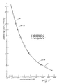
- the graph of Figure 1 is a plot of the viscosity [(log n (poise)] plotted as a function of temperature in °C.
- the solid line 20 is Example 11 (Ex-11) in the Chart II B set forth above.
- the viscosity-temperature curve is based upon various measured values of viscosity which were measured using three different melts of glass of the same composition. As such, the viscosity-temperature curve 20 depicts the desired characteristic of a glass composition of the present invention.
- the preferred embodiment of the glass composition is Example 9 (Ex-9) shown.
- the viscosity-temperature curve for Example 9 (Ex-9) is depicted by dashed line 22.
- the viscosity at the liquidus temperature stage is less than 104.
- firing temperature which is greater than 550°C, and the viscosity of the glass is well in excess of 1013 poise.
- T 7.6 the temperature is in the range of about 720°C to about 790°C.
- the viscosity of the glass is in the range of about 103 to about 105 poise.
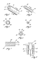
- the perspective view of Figure 2 shows a glass clad tube, shown generally as 28, formed of a glass composition of the present invention.
- the glass clad tube 28 has two ends which are shown as ends 30 and 32.
- the glass clad tube is cylindrical in shape and has a hollowed out central area 34 and an interior surface 36.
- the cross-sectional shape of the hollowed out central area 34 is preferably circular in cross-section.
- the exterior surface 40 of the glass clad tube 28 is circular.
- the outer surface 40 and the hollowed out central area 34 define a thick wall 38 to form the hollow glass tube 28.
- the hollowed out central area 34 extends axially through the center of the glass tube 28.
- FIG. 3 is a perspective view of a core glass rod, shown generally as 46.
- the glass rod 46 can be formed from any one of several known glass core compositions which is capable of being chemically etched.
- Several examples of compatible core glass can have the following composition:
- These glass core compositions have excellent etching characteristics and substantially the same lineal coefficient of thermal expansion as the glass composition used for the glass clad tube 28.
- a glass composition for core glass for use in manufacturing a high performance microchannel plate consisting essentially of the following composition in mole percent ranges: wherein the Re203 comprises any one or more of the Lanthanum Group rare earth oxides, the total mole percent of which is within the above mole percent ranges for Re203.
- the core glass rod 46 is solid in cross-section as depicted by the solid end 50.
- the exterior shape of the glass rod 46, defined by the exterior surface 48, is generally circular in cross-section.
- the diameter of the glass rod 46 is less than the diameter of the hollowed out central area 34 as defined in the glass tube 28 of Figure 2.
- Figure 2 shows that the hollowed out central area 34 defines an interior surface 36 which would be spaced from the exterior surface 48 of the glass rod of Figure 3.
- Figure 4 is a cross-sectional view taken along section lines 4-4 of Figure 2 showing the details of the cross-section of the glass clad tube 28.
- the glass clad tube 28 has an exterior surface 40, a hollowed out central area 34, an interior surface 36 and a thick wall 38.
- Figure 5 is a cross-sectional view taken along section line 5-5 of Figure 3 showing that the cross-section 50 of glass rod 46 is circular in cross-section and has an exterior surface 48.
- Figure 6 is a pictorial representation, in cross-section, of the core glass rod 46 of Figure 3 inserted into the hollowed out central area 34 of the glass clad tube 28 of Figure 2.
- Figure 6 illustrates that the exterior surface 48 of the glass rod 46 is spaced a predetermined distance from the inner surface 36 of thick wall 38 of the glass clad tube 28. The distance therebetween is referred to as space 60 and provides a means for permitting relative movement of the glass rod 46 within the interior of the glass clad tube 28.
- the width of the spacing could be in the order of about .001" to about .010". The spacing widths determined by a number of factors such as, for example, the bow of the glass rod 46, the tolerances of the hollowed out central area 34 of the glass clad tube 28 and the like.
- Figure 7 is a pictorial cross-section representation showing the relationship between the glass clad tube 28 and the glass rod 46.
- the combination is referred to as a clad/core glass assembly 52.
- the glass clad tube 28 and the glass rod 46 are fabricated of clear glass, with the glass composition of the glass rod 46 being susceptible to chemical etching by an appropriate etching solution.
- the clad/core glass assembly 52 is drawn into a glass fiber in accordance with the pictorial representation of a heating furnace illustrated in Figure 8.
- the clad/core glass assembly 52 is slowly fed downwards into furnace 56.
- the core glass assembly 52 has a holder 54 on top thereof to support and transport the subassembly 52 downward into the furnace 56.
- the furnace 56 includes heating coils 58 which are heated by applying electrical energy through input terminals 64. The heating coils 58 within the furnace 56 heat the lower end of the clad/core glass assembly 52 at point 62.
- the glass begins a viscous flow.
- the glass exhibits viscous flow to form a cone 66 as illustrated in Figure 8.
- the glass melting begins by forming or pulling a glass rod from cone 66 and extending the rod past the bottom of the furnace 46 where the rod then begins to harden.
- the rod is removed and the glass is then drawn downward forming a glass fiber 68.
- the fiber 68 is continuously drawn off of the viscous cone 66.
- the clad/core glass subassembly 52 is fed slowly into the furnace such that the lower end thereof is continuously heated and maintained at a constant temperature.
- the glass fiber 68 is drawn off the continuously heated subassembly at a continuous rate of speed forming a uniform diameter fiber.
- the clad tube and the glass core are fused together so that the fiber consists of a solid center core with a fused outer coating.
- the center core is of uniform diameter as is the outer core and the outer core is completely coated with no breaks, cracks or the like.
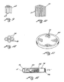
- Figure 9 is a pictorial representation of a plurality of drawn fibers 68 depicted as 68 formed into a multi fiber assembly. As illustrated in Figure 9, the fibers are individual cylindrical rods which have been reduced to a desired size, say in the order of 4,000 to 1. Each fiber 68 includes a glass core whose outer periphery is surrounded by a glass clad layer.
- the core of each of the fibers 68 is fabricated of material such that the core glass is etchable in an appropriate etching solution such that the core glass can be removed during subsequent processing to form a microchannel plate.
- the glass clad tube is made from a glass composition which has a softening temperature substantially the same as that of the glass core.
- the glass material of the clad tube is different from the glass material of the core glass in that the glass clad tube has a higher lead content which renders it non-etchable under those conditions used for etching the core glass material.
- the clad tube remains after the chemical etching of the glass core and becomes a means defining a pathway for electrons in the form of a chemically and thermally treated channel which is defined within the hollowed out central area of the clad glass.
- a plurality of hexagonal arrays 70, each having several thousand single fibers, are assembled into a multi-assembly.
- the multi-assembly is fused together in a furnace at appropriate temperatures to maintain the hexagonal configuration within an annular outer ring.
- the fused multi-assembly is ultimately cut into individual wafers to form microchannel plates 80.
- Figure 11 is a pictorial representation of a wafer 80 having a plurality of multi-assemblies 70 formed therein which is utilized for forming a multichannel plate. Subsequently, the wafer is subject to further processing to form the microchannels.
- the microchannels are formed by chemically etching the core glass from area 76, preferably by etching with a dilute acid. After etching, the clad glass 74 remains to form a microchannel which is illustrated in Figure 13. Also, the clad glass 74 remains solid and provides a mechanical support for the wafer 80 illustrated in Figure 11.
- the microchannel plates are heat treated in an atmosphere of hydrogen gas whereby certain reducible oxides, such as lead oxide, are reduced to render the clad tube inner channel surface electronically conductive.
- certain reducible oxides such as lead oxide
- a semiconductor layer is formed in each of the glass clad interior surfaces and the latter extends inwardly from the surface which defines a microchannel 76.
- Figure 13 is a pictorial representation of a microchannel 76 which has the interior surface thereof chemically and thermally treated to make the same subject to secondary emission.
- electron e- enters into the microchannel 76 it collides with the secondary emissive interior surface causing other electrons, such as electrons shown by lines 80, to be emitted from the secondary emission surface.
- the electrons e ⁇ emitted by the first collision again collide with the secondary emissive surface producing additional electrons shown by lines 84 which results in the amplification of the electron e ⁇ as it is transported through the microchannel 76.
- the electron e ⁇ is amplified to produce Ne ⁇ as depicted by electrons being emitted in the form of Ne ⁇ electrons shown as 86 in Figure 13.
- microchannel plates could be used in a wide variety of applications, such as for detecting charged particles, UV-Photon detection, X-ray and ion detection and for night vision glasses.
Landscapes
- Chemical & Material Sciences (AREA)
- Materials Engineering (AREA)
- Engineering & Computer Science (AREA)
- Chemical Kinetics & Catalysis (AREA)
- General Chemical & Material Sciences (AREA)
- Geochemistry & Mineralogy (AREA)
- Life Sciences & Earth Sciences (AREA)
- Organic Chemistry (AREA)
- Physics & Mathematics (AREA)
- General Physics & Mathematics (AREA)
- Optics & Photonics (AREA)
- Glass Compositions (AREA)
- Electron Tubes For Measurement (AREA)
- Common Detailed Techniques For Electron Tubes Or Discharge Tubes (AREA)
Applications Claiming Priority (2)
| Application Number | Priority Date | Filing Date | Title |
|---|---|---|---|
| US458849 | 1989-12-29 | ||
| US07/458,849 US5015909A (en) | 1989-12-29 | 1989-12-29 | Glass composition and method for manufacturing a high performance microchannel plate |
Publications (3)
| Publication Number | Publication Date |
|---|---|
| EP0439788A2 true EP0439788A2 (fr) | 1991-08-07 |
| EP0439788A3 EP0439788A3 (en) | 1992-04-08 |
| EP0439788B1 EP0439788B1 (fr) | 1995-04-12 |
Family
ID=23822335
Family Applications (1)
| Application Number | Title | Priority Date | Filing Date |
|---|---|---|---|
| EP90124783A Expired - Lifetime EP0439788B1 (fr) | 1989-12-29 | 1990-12-19 | Composition de verre et méthode de fabrication d'une plaque de microcanaux à haute performance |
Country Status (5)
| Country | Link |
|---|---|
| US (1) | US5015909A (fr) |
| EP (1) | EP0439788B1 (fr) |
| JP (1) | JPH04331741A (fr) |
| AT (1) | ATE121057T1 (fr) |
| DE (1) | DE69018604T2 (fr) |
Cited By (2)
| Publication number | Priority date | Publication date | Assignee | Title |
|---|---|---|---|---|
| US7144633B2 (en) | 2002-07-29 | 2006-12-05 | Evanite Fiber Corporation | Glass compositions |
| US7160824B2 (en) | 2002-07-29 | 2007-01-09 | Evanite Fiber Corporation | Glass compositions |
Families Citing this family (24)
| Publication number | Priority date | Publication date | Assignee | Title |
|---|---|---|---|---|
| US5108961A (en) * | 1989-12-29 | 1992-04-28 | Circon Corporation | Etchable core glass compositions and method for manufacturing a high performance microchannel plate |
| US5158812A (en) * | 1991-09-13 | 1992-10-27 | Corning Incorporated | Semiconducting glass and article |
| US5265327A (en) * | 1991-09-13 | 1993-11-30 | Faris Sadeg M | Microchannel plate technology |
| US6205819B1 (en) | 1994-06-16 | 2001-03-27 | The Regents Of The University Of California | Method for vacuum fusion bonding |
| US6103648A (en) * | 1998-05-28 | 2000-08-15 | Circon Corporation | Bulk conducting glass compositions and fibers |
| US6082140A (en) * | 1999-06-16 | 2000-07-04 | The Regents Of The University Of California | Fusion bonding and alignment fixture |
| US6303918B1 (en) * | 1999-08-25 | 2001-10-16 | Litton Systems, Inc. | Method and system for detecting radiation incorporating a hardened photocathode |
| JP3675326B2 (ja) * | 2000-10-06 | 2005-07-27 | キヤノン株式会社 | マルチチャネルプレートの製造方法 |
| KR100387984B1 (ko) * | 2001-02-16 | 2003-06-18 | 한국과학기술원 | 미소 채널 플레이트의 제조방법 |
| RU2235072C2 (ru) * | 2001-09-03 | 2004-08-27 | Государственное унитарное предприятие "Всероссийский научный центр "Государственный оптический институт им. С.И. Вавилова" | Способ изготовления волоконно-оптических элементов и микроканальных структур |
| RU2291124C2 (ru) * | 2003-11-04 | 2007-01-10 | Федеральное государственное унитарное предприятие "Научно-исследовательский и технологический институт оптического материаловедения Всероссийского научного центра "Государственный оптический институт им.С.И.Вавилова" (ФГУП "НИТИОМ ВНЦ"ГОИ им. С.И.Вавилова") | Микроканальная пластина |
| JP4567404B2 (ja) * | 2004-09-14 | 2010-10-20 | 浜松ホトニクス株式会社 | マイクロチャンネルプレート及びその製造方法 |
| US8207506B2 (en) * | 2007-07-03 | 2012-06-26 | Nova Scientific, Inc. | Neutron detection |
| US7791038B2 (en) * | 2007-07-03 | 2010-09-07 | Nova Scientific, Inc. | Neutron detection |
| US8445858B2 (en) * | 2008-11-19 | 2013-05-21 | Nova Scientific, Inc. | Neutron detection and collimation |
| DE102009027109B4 (de) * | 2009-06-23 | 2012-02-16 | Schott Ag | Bleihaltiges Weltraumglas, seine Herstellung und Verwendung |
| JP6949014B2 (ja) | 2015-10-22 | 2021-10-13 | コーニング インコーポレイテッド | 高透過率ガラス |
| CN111463102B (zh) * | 2020-05-09 | 2023-03-31 | 北方夜视技术股份有限公司 | 微通道板 |
| WO2022072209A1 (fr) | 2020-09-30 | 2022-04-07 | Corning Incorporated | Composition de verre sans plomb pour la fabrication de plaques à microcanaux |
| JP7519311B2 (ja) * | 2021-02-04 | 2024-07-19 | 新光電気工業株式会社 | 紫外線検出物及び紫外線検出装置、並びにそれらの製造方法 |
| WO2022183396A1 (fr) * | 2021-03-03 | 2022-09-09 | 中国建筑材料科学研究总院有限公司 | Composition de verre résistante au bombardement ionique, verre de revêtement de plaque à microcanaux, plaque à microcanaux et procédé de préparation |
| CN112979160B (zh) * | 2021-03-03 | 2025-09-12 | 中国建筑材料科学研究总院有限公司 | 耐离子轰击玻璃组合物、微通道板皮料玻璃、微通道板及制备方法 |
| CN116143407A (zh) * | 2022-11-16 | 2023-05-23 | 中建材光子科技有限公司 | 一种高二次电子产额、耐烘烤的玻璃材料及其制备方法 |
| JP2024158865A (ja) * | 2023-04-28 | 2024-11-08 | 株式会社ジーシー | ガラス組成物、及びx線造影性組成物 |
Family Cites Families (10)
| Publication number | Priority date | Publication date | Assignee | Title |
|---|---|---|---|---|
| GB1020795A (en) * | 1963-03-02 | 1966-02-23 | Obara Optical Glass | Laser glass |
| NL7005457A (fr) * | 1970-04-16 | 1971-10-19 | ||
| GB1455530A (en) * | 1975-04-23 | 1976-11-10 | Corning Glass Works | Barium borosilicate optical glasses |
| DE3228826C2 (de) * | 1982-08-02 | 1986-09-25 | Schott Glaswerke, 6500 Mainz | Hochabsorbierendes Pb-haltige Gläser für Kathodenstrahlröhrenbildschirme |
| DE3404363A1 (de) * | 1984-02-08 | 1985-08-14 | Schott Glaswerke, 6500 Mainz | Hoch pbo-haltige glaeser im system sio(pfeil abwaerts)2(pfeil abwaerts)pbo-m(pfeil abwaerts)2(pfeil abwaerts)o mit erhoehter chemischer bestaendigkeit |
| FR2563826B1 (fr) * | 1984-05-07 | 1991-08-30 | Verre Fluore Sa | Procedes de fabrication de fibres et de composants optiques en verres fluores et appareils destines a les mettre en oeuvre |
| DD239586C2 (de) * | 1985-07-23 | 1987-10-28 | Jenaer Glaswerk Veb | Optisches lanthankronglas mit erhoehtem inneren lichttransmissionsgrad |
| US4737475A (en) * | 1985-10-07 | 1988-04-12 | General Electric Company | Arsenic-free lead silicate vacuum tube glass |
| US4737013A (en) * | 1986-11-03 | 1988-04-12 | Litton Systems, Inc. | Microchannel plate having an etch limiting barrier |
| WO1990014316A1 (fr) * | 1989-05-17 | 1990-11-29 | National Research Development Corporation | Procede de fabrication d'objets presentant des sections transversales complexes de petite dimension |
-
1989
- 1989-12-29 US US07/458,849 patent/US5015909A/en not_active Expired - Lifetime
-
1990
- 1990-12-19 EP EP90124783A patent/EP0439788B1/fr not_active Expired - Lifetime
- 1990-12-19 DE DE69018604T patent/DE69018604T2/de not_active Expired - Fee Related
- 1990-12-19 AT AT90124783T patent/ATE121057T1/de not_active IP Right Cessation
- 1990-12-28 JP JP2416065A patent/JPH04331741A/ja active Pending
Cited By (5)
| Publication number | Priority date | Publication date | Assignee | Title |
|---|---|---|---|---|
| US7144633B2 (en) | 2002-07-29 | 2006-12-05 | Evanite Fiber Corporation | Glass compositions |
| US7160824B2 (en) | 2002-07-29 | 2007-01-09 | Evanite Fiber Corporation | Glass compositions |
| US8012629B2 (en) | 2002-07-29 | 2011-09-06 | Hollingsworth & Vose Company | Batteries containing bismuth glass compositions |
| US8211575B2 (en) | 2002-07-29 | 2012-07-03 | Hollingsworth & Vose Company | Batteries containing bismuth glass compositions |
| US7939166B2 (en) | 2004-07-21 | 2011-05-10 | Hollingsworth & Vose Company | Glass compositions |
Also Published As
| Publication number | Publication date |
|---|---|
| JPH04331741A (ja) | 1992-11-19 |
| EP0439788A3 (en) | 1992-04-08 |
| US5015909A (en) | 1991-05-14 |
| EP0439788B1 (fr) | 1995-04-12 |
| ATE121057T1 (de) | 1995-04-15 |
| DE69018604T2 (de) | 1996-01-04 |
| DE69018604D1 (de) | 1995-05-18 |
Similar Documents
| Publication | Publication Date | Title |
|---|---|---|
| EP0439788B1 (fr) | Composition de verre et méthode de fabrication d'une plaque de microcanaux à haute performance | |
| US5108961A (en) | Etchable core glass compositions and method for manufacturing a high performance microchannel plate | |
| US3979621A (en) | Microchannel plates | |
| US8052884B2 (en) | Method of fabricating microchannel plate devices with multiple emissive layers | |
| EP0413482B1 (fr) | Dynodes continus du type à couche mince | |
| US3275428A (en) | Method of making honeycomb structure | |
| US4853020A (en) | Method of making a channel type electron multiplier | |
| JP2001351509A (ja) | マイクロチャネルプレート | |
| US4112170A (en) | Composite glass articles for channel plate fabrication | |
| CN112794642A (zh) | 微通道板用硼硅酸盐基体玻璃材料及其制备方法 | |
| EP1568062B1 (fr) | Plaque a microcanaux comportant des microcannaux avec des ouvertures en forme d'entonnoir profond et/ou etage et procede de fabrication correspondant | |
| US5034354A (en) | Alkali-free multichannel plate and glass | |
| WO2009023365A1 (fr) | Détection de neutrons | |
| US3265480A (en) | Method of making metal and glass fiber structures | |
| US3900305A (en) | Method of forming conductive layer on oxide-containing surfaces | |
| US3241934A (en) | Method for making electron image transfer device | |
| US6521149B1 (en) | Solid chemical vapor deposition diamond microchannel plate | |
| WO1999061381A1 (fr) | Compositions et fibres de verre a conductivite de masse | |
| JPH0834635A (ja) | マイクロチャンネルプレート用融着ガラス | |
| US20020117960A1 (en) | Field emission wafer and process for making same for use in field emission display devices | |
| KR100499866B1 (ko) | 요철모양의 금형을 이용한 mcp 제작 방법 및 장치 | |
| EP4222125A1 (fr) | Composition de verre sans plomb pour la fabrication de plaques à microcanaux | |
| JP3936516B2 (ja) | ケイ酸鉛ガラス、それを用いた二次電子増倍管、およびその製造方法 | |
| US4305744A (en) | Method of making an electron multiplier device | |
| RU2291124C2 (ru) | Микроканальная пластина |
Legal Events
| Date | Code | Title | Description |
|---|---|---|---|
| PUAI | Public reference made under article 153(3) epc to a published international application that has entered the european phase |
Free format text: ORIGINAL CODE: 0009012 |
|
| AK | Designated contracting states |
Kind code of ref document: A2 Designated state(s): AT BE DE FR GB NL |
|
| PUAL | Search report despatched |
Free format text: ORIGINAL CODE: 0009013 |
|
| AK | Designated contracting states |
Kind code of ref document: A3 Designated state(s): AT BE DE FR GB NL |
|
| 17P | Request for examination filed |
Effective date: 19921001 |
|
| 17Q | First examination report despatched |
Effective date: 19930630 |
|
| GRAA | (expected) grant |
Free format text: ORIGINAL CODE: 0009210 |
|
| AK | Designated contracting states |
Kind code of ref document: B1 Designated state(s): AT BE DE FR GB NL |
|
| PG25 | Lapsed in a contracting state [announced via postgrant information from national office to epo] |
Ref country code: NL Free format text: LAPSE BECAUSE OF NON-PAYMENT OF DUE FEES Effective date: 19950412 Ref country code: FR Effective date: 19950412 Ref country code: BE Effective date: 19950412 Ref country code: AT Effective date: 19950412 |
|
| REF | Corresponds to: |
Ref document number: 121057 Country of ref document: AT Date of ref document: 19950415 Kind code of ref document: T |
|
| REF | Corresponds to: |
Ref document number: 69018604 Country of ref document: DE Date of ref document: 19950518 |
|
| EN | Fr: translation not filed | ||
| NLV1 | Nl: lapsed or annulled due to failure to fulfill the requirements of art. 29p and 29m of the patents act | ||
| PG25 | Lapsed in a contracting state [announced via postgrant information from national office to epo] |
Ref country code: GB Effective date: 19951219 |
|
| PLBE | No opposition filed within time limit |
Free format text: ORIGINAL CODE: 0009261 |
|
| STAA | Information on the status of an ep patent application or granted ep patent |
Free format text: STATUS: NO OPPOSITION FILED WITHIN TIME LIMIT |
|
| 26N | No opposition filed | ||
| GBPC | Gb: european patent ceased through non-payment of renewal fee |
Effective date: 19951219 |
|
| PGFP | Annual fee paid to national office [announced via postgrant information from national office to epo] |
Ref country code: DE Payment date: 19971229 Year of fee payment: 8 |
|
| PG25 | Lapsed in a contracting state [announced via postgrant information from national office to epo] |
Ref country code: DE Free format text: LAPSE BECAUSE OF NON-PAYMENT OF DUE FEES Effective date: 19991001 |