EP0439973B1 - Hydraulische Hilfsanlage für Bremskreis - Google Patents
Hydraulische Hilfsanlage für Bremskreis Download PDFInfo
- Publication number
- EP0439973B1 EP0439973B1 EP90403579A EP90403579A EP0439973B1 EP 0439973 B1 EP0439973 B1 EP 0439973B1 EP 90403579 A EP90403579 A EP 90403579A EP 90403579 A EP90403579 A EP 90403579A EP 0439973 B1 EP0439973 B1 EP 0439973B1
- Authority
- EP
- European Patent Office
- Prior art keywords
- chamber
- pusher
- auxiliary chamber
- auxiliary
- bore
- Prior art date
- Legal status (The legal status is an assumption and is not a legal conclusion. Google has not performed a legal analysis and makes no representation as to the accuracy of the status listed.)
- Expired - Lifetime
Links
- 239000012530 fluid Substances 0.000 claims description 19
- 230000009467 reduction Effects 0.000 claims description 2
- 239000007787 solid Substances 0.000 claims 1
- 230000007246 mechanism Effects 0.000 description 3
- 230000015556 catabolic process Effects 0.000 description 2
- 238000013016 damping Methods 0.000 description 2
- 238000006731 degradation reaction Methods 0.000 description 2
- 230000000994 depressogenic effect Effects 0.000 description 2
- 230000006870 function Effects 0.000 description 2
- 230000035807 sensation Effects 0.000 description 2
- 230000000295 complement effect Effects 0.000 description 1
- 230000006835 compression Effects 0.000 description 1
- 238000007906 compression Methods 0.000 description 1
- 230000006378 damage Effects 0.000 description 1
- 230000000593 degrading effect Effects 0.000 description 1
- 230000004048 modification Effects 0.000 description 1
- 238000012986 modification Methods 0.000 description 1
- 230000035939 shock Effects 0.000 description 1
Images


Classifications
-
- B—PERFORMING OPERATIONS; TRANSPORTING
- B60—VEHICLES IN GENERAL
- B60T—VEHICLE BRAKE CONTROL SYSTEMS OR PARTS THEREOF; BRAKE CONTROL SYSTEMS OR PARTS THEREOF, IN GENERAL; ARRANGEMENT OF BRAKING ELEMENTS ON VEHICLES IN GENERAL; PORTABLE DEVICES FOR PREVENTING UNWANTED MOVEMENT OF VEHICLES; VEHICLE MODIFICATIONS TO FACILITATE COOLING OF BRAKES
- B60T13/00—Transmitting braking action from initiating means to ultimate brake actuator with power assistance or drive; Brake systems incorporating such transmitting means, e.g. air-pressure brake systems
- B60T13/10—Transmitting braking action from initiating means to ultimate brake actuator with power assistance or drive; Brake systems incorporating such transmitting means, e.g. air-pressure brake systems with fluid assistance, drive, or release
- B60T13/12—Transmitting braking action from initiating means to ultimate brake actuator with power assistance or drive; Brake systems incorporating such transmitting means, e.g. air-pressure brake systems with fluid assistance, drive, or release the fluid being liquid
-
- B—PERFORMING OPERATIONS; TRANSPORTING
- B60—VEHICLES IN GENERAL
- B60T—VEHICLE BRAKE CONTROL SYSTEMS OR PARTS THEREOF; BRAKE CONTROL SYSTEMS OR PARTS THEREOF, IN GENERAL; ARRANGEMENT OF BRAKING ELEMENTS ON VEHICLES IN GENERAL; PORTABLE DEVICES FOR PREVENTING UNWANTED MOVEMENT OF VEHICLES; VEHICLE MODIFICATIONS TO FACILITATE COOLING OF BRAKES
- B60T13/00—Transmitting braking action from initiating means to ultimate brake actuator with power assistance or drive; Brake systems incorporating such transmitting means, e.g. air-pressure brake systems
- B60T13/10—Transmitting braking action from initiating means to ultimate brake actuator with power assistance or drive; Brake systems incorporating such transmitting means, e.g. air-pressure brake systems with fluid assistance, drive, or release
- B60T13/12—Transmitting braking action from initiating means to ultimate brake actuator with power assistance or drive; Brake systems incorporating such transmitting means, e.g. air-pressure brake systems with fluid assistance, drive, or release the fluid being liquid
- B60T13/14—Transmitting braking action from initiating means to ultimate brake actuator with power assistance or drive; Brake systems incorporating such transmitting means, e.g. air-pressure brake systems with fluid assistance, drive, or release the fluid being liquid using accumulators or reservoirs fed by pumps
- B60T13/141—Systems with distributor valve
Definitions
- the present invention relates to hydraulic assistance devices for the braking circuit of motor vehicles.
- Such a device is, for example, described in document EP-A-0 288 349 to which reference will be made in connection with its operation.
- Such a device comprises a body pierced with a bore in which slide coaxially a pusher controlled by a brake pedal and a piston means placed between first and second chambers containing a brake fluid, the first chamber receiving at at least one spring which loads the pusher and the piston means away from each other, the first and second chambers being connected to sources of fluid under low pressure and under high pressure by valve means.
- the spring provided in the first chamber constitutes a stroke simulator for the pedal which is generally linked to the pusher by means of a lever-forming mechanism.
- the invention therefore aims to obviate this drawback by ensuring damping of the return movement of the assembly without abnormally altering the brake release time or degrading the sensation received by the driver.
- an auxiliary chamber with variable volume as a function of the position of the pusher, formed in the bore communicates with the first chamber, on the one hand permanently by means of a restriction and on the other hand by means of an auxiliary valve means authorizing communication during the increase in volume of the auxiliary chamber and prohibiting it during the reduction of the latter.
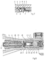
- the device comprises a body 30 pierced with a bore 32 in which a pusher 25 and a piston 34 slide coaxially.
- the brake pedal not shown, is fixed to the end 16 of the pusher 25 projecting from the bore 32.
- two springs 51 and 52 arranged in the first chamber 5, push the piston 34 and the pusher 25 away from one another.
- a plug 8 forms a stop inside the bore 32 for the pusher 25.
- the pusher 25 is provided with a blind bore 7 communicating with the first chamber 5.
- an auxiliary chamber 4 is formed between the pusher 25 and the bore 32, and communicates with the first chamber 5 via an opening 6 and the bore 7.
- a unidirectional seal 3 is fixed to the pusher 25 and separates the auxiliary chamber and the first chamber 5.
- This seal 3 is an elastic cup, the lip of which is located in the auxiliary chamber 4.
- the illustrated embodiment comprising two compression springs to simulate the stroke of the pedal according to two different laws, it is equally possible to fix the seal 3 either directly on the pusher 25 as illustrated in FIG. 3 or else indirectly via the cylinder 28 which constitutes the intermediate piece between the two springs 51, 52, as shown in FIG. 2, depending on the type of damping desired.
- the operation of the device is as follows.
- the chamber 5 is filled with brake fluid under low pressure.
- the pusher 25 slides to the right (in the Figures), first compressing the spring 51 and the spring 52 whose stiffnesses are generally different, until the parts come into abutment.
- a vacuum is created in the auxiliary chamber 4.
- the fluid in the chamber 5 then passes through the bore 7 and the opening 6 to penetrate into the auxiliary chamber 4 whose volume increases.
- the lip of the cup 3 moves apart, thus creating a complementary path to the flow of fluid towards the chamber 4. The sensation received by the driver at the pedal is therefore not degraded.
- Figure 4 differs from that of Figures 1 to 3 by the nature of the unidirectional seal used. Indeed, Figures 4 and 5, this seal consists of an annular segment 3 clamped in the bore 32, mounted floating between two stops 9 and 10 provided at the periphery of the pusher 25. The stop 9, opposite the chamber 4 , is drilled so as to provide passages for the brake fluid, while the stop 10, opposite the chamber 5 is full.
- the seal 3 When moving the pusher to the right (in Figure 4), the seal 3 is supported on the drilled stop 9, which provides a passage for the brake fluid between the chamber 5 and the chamber 4 via the space left free between the end of the stop 10 and the bore 32. On returning from the pusher, the seal 3 rests on the full stop 10 thus closing the aforementioned space and preventing any flow of fluid between the chambers 4 and 5 by this path. The fluid must then pass through the orifice 6 which constitutes the aforementioned restriction.
- Figures 6 and 7 also differs from the previous ones in particular by the unidirectional seal used.
- the joint 3 is constituted by a ball closing, at rest, an opening 12 formed between chamber 4 and conduit 7.
- ball 3 lifts and the fluid enters the chamber 4.
- a cage 9, 10 is judiciously formed in the pusher 25 to guide the ball.
- the ball 3 On returning from the pusher, the ball 3 is pushed onto its seat by the pressure in the chamber 4 and closes the orifice 12, preventing any flow of the fluid by this path. The fluid must then flow through the orifice 6 and the space between the stop 10 and the internal wall of the chamber which together constitute the aforementioned restriction.
- the orifice 6 is made on a wall 10 of the ball cage, but it could have been made in accordance with the teachings of the previous figures.
- the embodiment shown in Figure 8 is somewhat different from the previous ones, in that the auxiliary chamber is located inside the first chamber 5, the two springs 51 and 52 being aligned and not one in the middle of the other.
- the piston 34 is provided with a rod 80 whose free end 10 enters a cylinder 17 connected to the pusher 25, here by means of an intermediate piece 20 disposed between the two springs.
- the volume between the intermediate part 20 and the free end 10 of the rod 80 communicates with the first chamber 5 by means of holes 23.
- a unidirectional seal 3 is disposed at the free end of the rod 80 so as to allow a flow of fluid when the pusher 25 moves to the right (in the Figure) and prevent the reverse flow upon return of the pusher.
- the seal 3 is of the elastic cup type as used in the embodiment of Figures 1, 2 and 3, but it could as well be of the floating segment type as used in the realization of Figures 4 and 5.
Landscapes
- Engineering & Computer Science (AREA)
- Transportation (AREA)
- Mechanical Engineering (AREA)
- Transmission Of Braking Force In Braking Systems (AREA)
- Braking Systems And Boosters (AREA)
Claims (6)
- Hydraulische Hilfsanlage für einen Bremskreis, mit einem von einer Bohrung (32) durchsetzten Körper (30), in dem koaxial ein durch ein Bremspedal gesteuerter Stößel (25) und ein Kolbemnmittel (34) gleiten, das zwischen eine erste (5) und eine zweite Kammer gesetzt ist, die ein Bremsfluid enthalten, wobei die erste Kammer (5) wenigstens eine Feder (51, 52) aufnimmt, die den Stößel (25) und das Kolbenmittel (34) voneinander im Abstand vorspannt, wobei die erste und die zweite Kammer durch Ventilmittel an Quellen mit Fluid unter Nieder- und Hochdruck angeschlossen sind, dadurch gekennzeichnet, daß eine in der Bohrung (32) ausgebildete Hilfskammer (4) mit in Abhängigkeit von der Position des Stößels (25) variablem Volumen mit der ersten Kammer (5) einerseits ständig über eine Drosselstelle (6) in Verbindung steht und andererseits über ein Hilfsventilmittel (3), das die Verbindung bei der Volumenerhöhung der Hilfskammer (4) zuläßt und die Verbindung bei der Volumenverminderung verbietet.
- Vorrichtung nach Anspruch 1, dadurch gekennzeichnet, daß die Hilfskammer (4) eine zwischen dem Stößel 25 und der Bohrung (32) vorgesehene, ringförmige Kammer ist, und daß sie von der ersten Kammer (5) durch eine Einwegdichtung (3) getrennt ist.
- Vorrichtung nach Anspruch 2, dadurch gekennzeichnet, daß die Einwegdichtung (3) durch eine Kugel gebildet ist, die in der Hilfskammer (4) aufgenommen und in der Lage ist, eine Leitung (12) zu verschließen, die zwischen der ersten Kammer (5) und der Hilfskammer (4) ausgebildet ist.
- Vorrichtung nach Anspruch 1, dadurch gekennzeichnet, daß die Hilfskammer (4) im Inneren der ersten Kammer (5) vorgesehen ist, und daß sie durch das zwischen einer in einem Zylinder (17) gleitendem Stange (80) vorgesehene Volumen bestimmt ist, wobei die Stange an dem Kolben (34) und der Zylinder, möglicherweise mittels eine Zwischenstücks (20), an dem Stößel (25) befestigt sind, wobei das freie Ende (10) der Stange (80) eine Einwegdichtung (3) trägt und der Raum (6) zwischen dem freien Ende des Zylinders (17) und der Wand der Stange (80) die Drosselstelle bildet.
- Vorrichtung nach Anspruch 2 oder 4, dadurch gekennzeichnet, daß die Einwegdichtung (3) ein elastischer Teller ist, dessen Lippe sich in der Hilfskammer (4) befindet.
- Vorrichtung nach Anspruch 2 oder 4, dadurch gekennzeichnet, daß die Einwegdichtung (3) ein ringförmiges Segment ist, das in die Bohrung (32) eingespännt und schwebend zwischen zwei Anschlägen (9, 10) angebracht ist, die am Umfang des Stößels (25) zwischen der ersten Kammer (5) und der Hilfskammer (4) vorgesehen sind, wobei der der Hilfskammer (4) zugewandte Anschlag (9) durchbohrt ist, während der der ersten Kammer (5) zugewandte Anschlag (10) massiv ist.
Applications Claiming Priority (2)
| Application Number | Priority Date | Filing Date | Title |
|---|---|---|---|
| FR9001118A FR2657574B1 (fr) | 1990-01-31 | 1990-01-31 | Dispositif d'assistance hydraulique pour circuit de freinage a amortisseur de course au relachement de la pedale de frein. |
| FR9001118 | 1990-01-31 |
Publications (2)
| Publication Number | Publication Date |
|---|---|
| EP0439973A1 EP0439973A1 (de) | 1991-08-07 |
| EP0439973B1 true EP0439973B1 (de) | 1993-06-16 |
Family
ID=9393267
Family Applications (1)
| Application Number | Title | Priority Date | Filing Date |
|---|---|---|---|
| EP90403579A Expired - Lifetime EP0439973B1 (de) | 1990-01-31 | 1990-12-13 | Hydraulische Hilfsanlage für Bremskreis |
Country Status (6)
| Country | Link |
|---|---|
| US (1) | US5086688A (de) |
| EP (1) | EP0439973B1 (de) |
| JP (1) | JPH04356267A (de) |
| DE (1) | DE69001996T2 (de) |
| ES (1) | ES2042249T3 (de) |
| FR (1) | FR2657574B1 (de) |
Families Citing this family (2)
| Publication number | Priority date | Publication date | Assignee | Title |
|---|---|---|---|---|
| JP3489453B2 (ja) * | 1997-08-08 | 2004-01-19 | トヨタ自動車株式会社 | ブレーキストロークシミュレータ |
| DE102017211872A1 (de) * | 2017-07-12 | 2019-01-17 | Robert Bosch Gmbh | Hauptbremszylinder für eine hydraulische Fahrzeugbremsanlage |
Family Cites Families (14)
| Publication number | Priority date | Publication date | Assignee | Title |
|---|---|---|---|---|
| US2814364A (en) * | 1956-12-31 | 1957-11-26 | David W Lowe | Railway car impact retarder |
| US3168812A (en) * | 1958-03-19 | 1965-02-09 | Glenn T Randol | Hydraulic thrust-transmitting device |
| DE2164591C3 (de) * | 1971-12-24 | 1979-06-21 | Alfred Teves Gmbh, 6000 Frankfurt | Zweikreis-Hauptzylinder für eine Druckspeicher-Bremsanlage, insbesondere für Kraftfahrzeuge |
| FR2391884A2 (fr) * | 1976-04-12 | 1978-12-22 | Ferodo Sa | Commande hydraulique notamment de freins de vehicules automobiles |
| GB1585870A (en) * | 1977-11-05 | 1981-03-11 | Girling Ltd | Hydraulic control assemblies for vehicle braking systems |
| US4588054A (en) * | 1979-07-11 | 1986-05-13 | Lebaron Chester F | Linear motion damper |
| US4278009A (en) * | 1979-08-23 | 1981-07-14 | General Motors Corporation | Hydraulic brake booster |
| FR2473144A1 (fr) * | 1980-01-04 | 1981-07-10 | Fournales France Sarl | Dispositif combine amortisseur et suspension pour vehicule |
| JPS5768942U (de) * | 1980-10-14 | 1982-04-24 | ||
| US4558767A (en) * | 1983-02-03 | 1985-12-17 | Tayco Developments, Inc. | Fluid amplified shock absorber with rebound stiffening construction |
| US4656924A (en) * | 1984-09-10 | 1987-04-14 | Dresser Industries, Inc. | Pulsation limiter for manually actuated hydraulic valve |
| FR2620099B1 (fr) * | 1987-03-31 | 1989-12-01 | Bendix France | Dispositif d'assistance hydraulique pour circuit de freinage |
| US4938324A (en) * | 1988-12-05 | 1990-07-03 | Bike-O-Matic, Inc. | Automatic derailleur shifter |
| US4998950A (en) * | 1990-02-02 | 1991-03-12 | General Motors Corporation | Center compensating master cylinder |
-
1990
- 1990-01-31 FR FR9001118A patent/FR2657574B1/fr not_active Expired - Lifetime
- 1990-12-13 ES ES199090403579T patent/ES2042249T3/es not_active Expired - Lifetime
- 1990-12-13 EP EP90403579A patent/EP0439973B1/de not_active Expired - Lifetime
- 1990-12-13 DE DE9090403579T patent/DE69001996T2/de not_active Expired - Fee Related
-
1991
- 1991-01-11 US US07/639,844 patent/US5086688A/en not_active Expired - Fee Related
- 1991-01-31 JP JP3029256A patent/JPH04356267A/ja not_active Withdrawn
Also Published As
| Publication number | Publication date |
|---|---|
| FR2657574B1 (fr) | 1992-04-24 |
| DE69001996D1 (de) | 1993-07-22 |
| DE69001996T2 (de) | 1993-09-23 |
| EP0439973A1 (de) | 1991-08-07 |
| JPH04356267A (ja) | 1992-12-09 |
| US5086688A (en) | 1992-02-11 |
| ES2042249T3 (es) | 1993-12-01 |
| FR2657574A1 (fr) | 1991-08-02 |
Similar Documents
| Publication | Publication Date | Title |
|---|---|---|
| FR2502567A1 (fr) | Dispositif de multiplication de la puissance de freinage pour systeme de freins d'automobile | |
| FR2479760A1 (fr) | Amplificateur de force commande mecaniquement, notamment pour installations de freinage hydraulique de vehicules automobiles | |
| FR2545055A1 (fr) | Amplificateur de force hydraulique, notamment pour systeme de freinage de vehicule automobile | |
| FR2751602A1 (fr) | Dispositif de freinage assiste a rapport d'assistance variable | |
| FR2537524A1 (fr) | Amplificateur de force de freinage a depression | |
| EP0939713B1 (de) | Hilfskraftbremsvorrichtung mit variablem verstärkerverhältnis und verringerter hysterese | |
| FR2673410A1 (fr) | Servomoteur d'assistance au freinage a saut reglable et procede de reglage du saut. | |
| FR2560841A1 (fr) | Generateur de pression de freinage | |
| EP0467725B1 (de) | Hydraulikantrieb mit Nachstellvorrichtung | |
| FR2630694A1 (fr) | Servomoteur d'assistance au freinage | |
| EP0439973A1 (de) | Hydraulische Hilfsanlage für Bremskreis | |
| FR2680347A1 (fr) | Unite d'actionnement pour systeme hydraulique de freinage pour vehicule a moteur. | |
| FR2598982A1 (fr) | Dispositif de regulation du glissement de traction. | |
| FR2595637A1 (fr) | Dispositif d'actionnement d'un embrayage a commande hydraulique | |
| EP0493155B1 (de) | Ventil und Verfahren zur Hydraulikkreislaufentlüftung | |
| EP1080002B1 (de) | Pneumatischer bremskraftverstärker mit schwimmender reaktionsscheibe und dynamisch annulierbarer reaktion | |
| EP0192546B1 (de) | Hydraulischer Bremskraftverstärker | |
| EP0210096B1 (de) | Hydraulische Hilfsanlage | |
| FR2724356A1 (fr) | Servomoteur pneumatique d'assistance au freinage | |
| EP1097073B1 (de) | Verbesserter hauptzylinder mit hydraulischer reaktion und selektiver selbstverstärkung | |
| EP0378947A1 (de) | Entlüftungsventil | |
| EP0991555B1 (de) | Hauptzylinder mit hydraulisch dynamischer reaktion geregelt durch einen querschnittsunterschied | |
| FR2492757A2 (fr) | Unite de freinage assiste pour vehicules automobiles | |
| FR2599323A1 (fr) | Dispositif d'assistance hydraulique. | |
| FR2539365A1 (fr) | Dispositif hydraulique de commande de freinage |
Legal Events
| Date | Code | Title | Description |
|---|---|---|---|
| PUAI | Public reference made under article 153(3) epc to a published international application that has entered the european phase |
Free format text: ORIGINAL CODE: 0009012 |
|
| 17P | Request for examination filed |
Effective date: 19901217 |
|
| AK | Designated contracting states |
Kind code of ref document: A1 Designated state(s): DE ES FR GB IT |
|
| 17Q | First examination report despatched |
Effective date: 19921125 |
|
| GRAA | (expected) grant |
Free format text: ORIGINAL CODE: 0009210 |
|
| ITF | It: translation for a ep patent filed | ||
| AK | Designated contracting states |
Kind code of ref document: B1 Designated state(s): DE ES FR GB IT |
|
| REF | Corresponds to: |
Ref document number: 69001996 Country of ref document: DE Date of ref document: 19930722 |
|
| GBT | Gb: translation of ep patent filed (gb section 77(6)(a)/1977) |
Effective date: 19930629 |
|
| REG | Reference to a national code |
Ref country code: ES Ref legal event code: FG2A Ref document number: 2042249 Country of ref document: ES Kind code of ref document: T3 |
|
| RAP2 | Party data changed (patent owner data changed or rights of a patent transferred) |
Owner name: ALLIEDSIGNAL EUROPE SERVICES TECHNIQUES |
|
| PLBE | No opposition filed within time limit |
Free format text: ORIGINAL CODE: 0009261 |
|
| STAA | Information on the status of an ep patent application or granted ep patent |
Free format text: STATUS: NO OPPOSITION FILED WITHIN TIME LIMIT |
|
| 26N | No opposition filed | ||
| PGFP | Annual fee paid to national office [announced via postgrant information from national office to epo] |
Ref country code: GB Payment date: 19961204 Year of fee payment: 7 |
|
| PGFP | Annual fee paid to national office [announced via postgrant information from national office to epo] |
Ref country code: FR Payment date: 19961213 Year of fee payment: 7 |
|
| PGFP | Annual fee paid to national office [announced via postgrant information from national office to epo] |
Ref country code: DE Payment date: 19961223 Year of fee payment: 7 |
|
| PGFP | Annual fee paid to national office [announced via postgrant information from national office to epo] |
Ref country code: ES Payment date: 19961228 Year of fee payment: 7 |
|
| PG25 | Lapsed in a contracting state [announced via postgrant information from national office to epo] |
Ref country code: GB Free format text: LAPSE BECAUSE OF NON-PAYMENT OF DUE FEES Effective date: 19971213 |
|
| PG25 | Lapsed in a contracting state [announced via postgrant information from national office to epo] |
Ref country code: FR Free format text: THE PATENT HAS BEEN ANNULLED BY A DECISION OF A NATIONAL AUTHORITY Effective date: 19971231 |
|
| GBPC | Gb: european patent ceased through non-payment of renewal fee |
Effective date: 19971213 |
|
| PG25 | Lapsed in a contracting state [announced via postgrant information from national office to epo] |
Ref country code: DE Free format text: LAPSE BECAUSE OF NON-PAYMENT OF DUE FEES Effective date: 19980901 |
|
| REG | Reference to a national code |
Ref country code: FR Ref legal event code: ST |
|
| PG25 | Lapsed in a contracting state [announced via postgrant information from national office to epo] |
Ref country code: ES Free format text: LAPSE BECAUSE OF NON-PAYMENT OF DUE FEES Effective date: 19981214 |
|
| REG | Reference to a national code |
Ref country code: ES Ref legal event code: FD2A Effective date: 19990114 |
|
| PG25 | Lapsed in a contracting state [announced via postgrant information from national office to epo] |
Ref country code: IT Free format text: LAPSE BECAUSE OF NON-PAYMENT OF DUE FEES;WARNING: LAPSES OF ITALIAN PATENTS WITH EFFECTIVE DATE BEFORE 2007 MAY HAVE OCCURRED AT ANY TIME BEFORE 2007. THE CORRECT EFFECTIVE DATE MAY BE DIFFERENT FROM THE ONE RECORDED. Effective date: 20051213 |