EP0439985A1 - Procédé et dispositif de filtration-régulation de débit notamment pour installation de traitement des eaux de piscines - Google Patents
Procédé et dispositif de filtration-régulation de débit notamment pour installation de traitement des eaux de piscines Download PDFInfo
- Publication number
- EP0439985A1 EP0439985A1 EP90450020A EP90450020A EP0439985A1 EP 0439985 A1 EP0439985 A1 EP 0439985A1 EP 90450020 A EP90450020 A EP 90450020A EP 90450020 A EP90450020 A EP 90450020A EP 0439985 A1 EP0439985 A1 EP 0439985A1
- Authority
- EP
- European Patent Office
- Prior art keywords
- water
- tank
- filtration
- filtered
- swimming pool
- Prior art date
- Legal status (The legal status is an assumption and is not a legal conclusion. Google has not performed a legal analysis and makes no representation as to the accuracy of the status listed.)
- Granted
Links
- XLYOFNOQVPJJNP-UHFFFAOYSA-N water Substances O XLYOFNOQVPJJNP-UHFFFAOYSA-N 0.000 title claims abstract description 68
- 238000001914 filtration Methods 0.000 title claims abstract description 29
- 230000009182 swimming Effects 0.000 title claims abstract description 18
- 238000000034 method Methods 0.000 title claims abstract description 8
- 230000005484 gravity Effects 0.000 claims abstract description 8
- 238000009434 installation Methods 0.000 claims description 14
- 238000004064 recycling Methods 0.000 claims description 3
- 238000011084 recovery Methods 0.000 claims description 2
- 230000001105 regulatory effect Effects 0.000 claims description 2
- 238000004891 communication Methods 0.000 abstract description 2
- 230000033228 biological regulation Effects 0.000 description 5
- 238000010586 diagram Methods 0.000 description 2
- 238000004519 manufacturing process Methods 0.000 description 2
- 239000000523 sample Substances 0.000 description 2
- 239000003795 chemical substances by application Substances 0.000 description 1
- 238000004140 cleaning Methods 0.000 description 1
- 230000007423 decrease Effects 0.000 description 1
- 230000001419 dependent effect Effects 0.000 description 1
- 238000001514 detection method Methods 0.000 description 1
- 238000009826 distribution Methods 0.000 description 1
- 238000001704 evaporation Methods 0.000 description 1
- 230000008020 evaporation Effects 0.000 description 1
- 230000006870 function Effects 0.000 description 1
- 238000002347 injection Methods 0.000 description 1
- 239000007924 injection Substances 0.000 description 1
- 239000000463 material Substances 0.000 description 1
- 238000012986 modification Methods 0.000 description 1
- 230000004048 modification Effects 0.000 description 1
- 239000004570 mortar (masonry) Substances 0.000 description 1
- 239000002245 particle Substances 0.000 description 1
- 238000005325 percolation Methods 0.000 description 1
- 229920000728 polyester Polymers 0.000 description 1
- 230000000750 progressive effect Effects 0.000 description 1
- 230000003134 recirculating effect Effects 0.000 description 1
- 230000009711 regulatory function Effects 0.000 description 1
- 239000004576 sand Substances 0.000 description 1
- 238000004513 sizing Methods 0.000 description 1
- 239000000126 substance Substances 0.000 description 1
- 238000011144 upstream manufacturing Methods 0.000 description 1
- 239000003643 water by type Substances 0.000 description 1
Images
Classifications
-
- B—PERFORMING OPERATIONS; TRANSPORTING
- B01—PHYSICAL OR CHEMICAL PROCESSES OR APPARATUS IN GENERAL
- B01D—SEPARATION
- B01D24/00—Filters comprising loose filtering material, i.e. filtering material without any binder between the individual particles or fibres thereof
- B01D24/02—Filters comprising loose filtering material, i.e. filtering material without any binder between the individual particles or fibres thereof with the filter bed stationary during the filtration
- B01D24/20—Filters comprising loose filtering material, i.e. filtering material without any binder between the individual particles or fibres thereof with the filter bed stationary during the filtration the filtering material being provided in an open container
- B01D24/22—Downward filtration, the filter material being supported by pervious surfaces
-
- B—PERFORMING OPERATIONS; TRANSPORTING
- B01—PHYSICAL OR CHEMICAL PROCESSES OR APPARATUS IN GENERAL
- B01D—SEPARATION
- B01D24/00—Filters comprising loose filtering material, i.e. filtering material without any binder between the individual particles or fibres thereof
- B01D24/38—Feed or discharge devices
- B01D24/386—Feed or discharge devices internal recirculation
-
- B—PERFORMING OPERATIONS; TRANSPORTING
- B01—PHYSICAL OR CHEMICAL PROCESSES OR APPARATUS IN GENERAL
- B01D—SEPARATION
- B01D24/00—Filters comprising loose filtering material, i.e. filtering material without any binder between the individual particles or fibres thereof
- B01D24/38—Feed or discharge devices
- B01D24/40—Feed or discharge devices for feeding
-
- B—PERFORMING OPERATIONS; TRANSPORTING
- B01—PHYSICAL OR CHEMICAL PROCESSES OR APPARATUS IN GENERAL
- B01D—SEPARATION
- B01D24/00—Filters comprising loose filtering material, i.e. filtering material without any binder between the individual particles or fibres thereof
- B01D24/38—Feed or discharge devices
- B01D24/42—Feed or discharge devices for discharging filtrate
-
- B—PERFORMING OPERATIONS; TRANSPORTING
- B01—PHYSICAL OR CHEMICAL PROCESSES OR APPARATUS IN GENERAL
- B01D—SEPARATION
- B01D24/00—Filters comprising loose filtering material, i.e. filtering material without any binder between the individual particles or fibres thereof
- B01D24/48—Filters comprising loose filtering material, i.e. filtering material without any binder between the individual particles or fibres thereof integrally combined with devices for controlling the filtration
- B01D24/4869—Filters comprising loose filtering material, i.e. filtering material without any binder between the individual particles or fibres thereof integrally combined with devices for controlling the filtration by level measuring
-
- E—FIXED CONSTRUCTIONS
- E04—BUILDING
- E04H—BUILDINGS OR LIKE STRUCTURES FOR PARTICULAR PURPOSES; SWIMMING OR SPLASH BATHS OR POOLS; MASTS; FENCING; TENTS OR CANOPIES, IN GENERAL
- E04H4/00—Swimming or splash baths or pools
- E04H4/12—Devices or arrangements for circulating water, i.e. devices for removal of polluted water, cleaning baths or for water treatment
- E04H4/1209—Treatment of water for swimming pools
Definitions
- the present invention relates in particular to swimming pool water treatment installations and more specifically to the filtration and regulation of the water flow rate of such installations.
- the buffer tank makes it possible to regulate the level of the water in the basin l as a function of the number of bathers and authorizes the overflow of the basin into the troughs 2 to ensure creaming.
- the buffer tank 4, on the one hand, and the pump 6 - filter 7 assembly, on the other hand, are functionally and physically dissociated, which means that major civil engineering work is required, which is further increased by the need for large sizing. the buffer tank so that it properly fulfills its regulatory function.
- the rate of renewal of the water in the basin l is highly dependent on the clogging of the filter 7 located downstream of the pump 6, so that this rate decreases at the same time as the filter clogs.
- the aim of the present invention is to overcome these various drawbacks by proposing a new filtration and regulation technique for the flow of renewal water, in particular from swimming pools, recreational pools or the like.
- the subject of the invention is a method of filtration-regulation of flow rate, in particular for installation for treating swimming pool water, using gravity filtration in the open air, the filtered water being sent to a tank set to l atmosphere, in a controlled manner so as to preserve in said tank a height of water which is preferably substantially constant, and then take up of said tank and sent into the water circuit for renewing the swimming pool, characterized in that it consists of subject all of the water, in particular from the overflow of the basin, to said gravity filtration, at constant load, by collecting the excess of raw water to be filtered and storing it in a buffer tank for automatic subsequent recycling in the circuit of filtration.
- the invention also relates to a filtration-regulation device for implementing the above method, comprising an open upper tank comprising a filtering floor supporting a granular filtration bed above which the raw water to be filtered is admitted coming from in particular from the pool water recovery network, a lower tank also open, supplied with filtered water in a controlled manner so as to maintain a substantially constant level of filtered water, and a circuit taking the filtered water to return it to the renewal circuit of water from the swimming pool basin, characterized in that it further comprises a buffer tank, also open, adjacent to said upper tank and communicating with the latter by a weir, a recirculation pump taking water from the tank buffer and reintroducing it into said upper tank, under the control of a water level detector in the upper tank, above the filter bed.
- Such a device ensures both filtration and regulation of the flow rate of the pool renewal water and is in the form of an extremely compact unit or module of reduced dimensions compared to conventional units, very substantially larger and located in separate and charged places, one, to filter and recycle the water, the other, to regulate (traditional buffer tank) the overflowing waters of the pool.
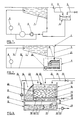
- FIG. 3 is a detailed view of the module 9 in vertical section.
- the module has the general shape of a rectangular enclosure partitioned into three tanks, all in the atmosphere, namely an upper filtration tank 12, a lower tank 13 for storing and recirculating the filtered water and a side tank 14 acting as a buffer tank.
- the tanks are constituted for example by molded polyester shells.
- the upper tank 12 comprises a filtering floor 15 delimiting an upper space where there is a thick granular filtration bed 16 and a lower space 17 serving as a reserve of filtered water.
- the filtering floor 15 is for example made up, in the known manner, of porous slabs joined by a mortar and carried by rafters. Below the floor is arranged a network of pipes 18 supplied with compressed air by means of a valve 19 and intended for cleaning, also in known manner, the floor 15.
- the floor supports a granular filter bed 16 of conventional type, for example sand, or any other granular filter material distributed in one or more layers of different nature and particle size, of an appropriate thickness.
- a granular filter bed 16 of conventional type for example sand, or any other granular filter material distributed in one or more layers of different nature and particle size, of an appropriate thickness.
- the raw water to be filtered 20 is brought by gravity into the tank 12, above the bed 16 by a pipe 21 connected to said pipes 3 and 10.
- This raw water to be filtered 20 is contained in the upper part of the tank 12 whose wall 22 facing the buffer tank 14 is at a level slightly lower than that of the other three walls of the tank, in order to constitute an overflow weir 23 towards said tray 14.
- the water in the tank 14 is raised and poured into the tank 12 by a pipe 24 provided with a recirculation pump 25 controlled by a level detector 26 placed in the tank 12.
- the lower tank 13 is brought into the open air by a communication symbolized at 27 in FIG. 3.
- This tank is responsible for storing the filtered water 28 transferred from the space 17 by a pipe 29 provided with a valve 30 of flow control responsible for compensating the pressure drop of the filter due to its progressive fouling and controlled by a level measuring member 31 disposed in the tank 13.
- the valve 30 is a butterfly type valve with quarter-turn positioning and the detector 31 is a capacitive probe immersed in the filtered water (17).
- the filtered water is taken up in the tank 13 by a pipe 32 in which the main pump 33 supplying the pool 1 of the swimming pool is interposed.
- this pipe 32 are introduced any treatment agents (8, FIG. 2) for the water.
- the water to be filtered arrives in the tank 12 through the pipe 21.
- the excess water is poured into the buffer tank 14.
- the detector 26 automatically activates the recirculation pump 25 which returns the raw water from the buffer tank 14 and pours it into the tank 12 to raise the level so that permanently the filter 16 works practically at constant load.
- a pipe 34 provided with a valve 35 and connected to the water distribution network allows, if necessary, a supply of new water.
- the water flows by downward percolation through the filter bed 16 and the floor 15 and is collected in the space 17. It is sent to the tank 13 by the valve 30.
- the valve 30 acts as a member for regulating the flow of water filtered from the space 17. It must at any time allow the passage of a constant flow rate equal to the flow rate of the pump 33 supplying the swimming pool.
- the open position of the valve 30 is controlled by the height h of the tank 13 measured using the detection probe 31 according to the following protocol: a drop in the level h signifies a drop in the filtration rate attributable to the fouling of the filter 16; to compensate for this pressure drop, the valve 30 must offer a larger passage opening until the level h displayed on the detector 31 stabilizes.
- the main pump 33 thus operates continuously with a water height h which is substantially constant at suction.
- Filter 16 which is an open gravity filter at constant load, provides better quality of filtration than a pressure filter.
- tank 12 Such an integrated design of filtration (tank 12) and of flow regulation (tank 14) makes it possible to produce an assembly or module 9 remarkably compact by its volume and dimensions.
- the tanks 12, 13 and 14 are grouped together with their additional equipment (pumps, valves, pipes, control cabinet, etc.) to form a unitary parallelepiped assembly that is simpler to manufacture, install and maintain.
Landscapes
- Chemical & Material Sciences (AREA)
- Chemical Kinetics & Catalysis (AREA)
- Engineering & Computer Science (AREA)
- Architecture (AREA)
- Water Supply & Treatment (AREA)
- Civil Engineering (AREA)
- Structural Engineering (AREA)
- Filtration Of Liquid (AREA)
- Treatment Of Water By Oxidation Or Reduction (AREA)
- Separation Using Semi-Permeable Membranes (AREA)
- Water Treatment By Sorption (AREA)
Abstract
Description
- La présente invention a trait en particulier aux installations de traitement des eaux de piscines et plus précisément à la filtration et à la régulation du débit de l'eau de telles installations.
- Une installation de traitement d'eau d'une piscine, telle qu'une piscine publique notamment, regroupe, comme illustré schématiquement par la figure 1 du dessin ci-annexé, un certain nombre d'éléments, à savoir :
- un bassin 1 entouré sur un, deux, trois ou quatre côtés d'un réseau de goulottes 2, équipé d'une grille de recouvrement ;
- un réseau de canalisations 3 récupérant les eaux recueillies par ces goulottes 2 ;
- un bac tampon 4 récupérant les eaux véhiculées par les canalisations 3 et recevant de temps en temps par une canalisation 5 de l'eau de compensation d'évaporation ;
- une installation de filtration et de traitement chimique comprenant notamment une pompe 6, un filtre 7 et une unité 8 d'injection dans l'eau de retour vers le bassin 1 de produits de traitement, cette installation étant reliée en amont à la fois au bassin 1 et au bac tampon 4.
- Dans une telle installation, le bac tampon permet de réguler le niveau des eaux dans le bassin l en fonction du nombre de baigneurs et autorise le débordement du bassin dans les goulottes 2 pour assurer l'écrémage.
- Ce type d'installation présente un certain nombre d'inconvénients.
- Le bac tampon 4, d'une part, et l'ensemble pompe 6 - filtre 7, d'autre part, sont fonctionnellement et physiquement dissociés ce qui oblige à des travaux de génie civil importants, accrus par ailleurs par la nécessité de dimensionner largement le bac tampon pour qu'il remplisse convenablement sa fonction de régulation.
- De plus, le débit de renouvellement de l'eau dans le bassin l est fortement tributaire de l'encrassement du filtre 7 situé en aval de la pompe 6, si bien que ce débit baisse en même temps que le filtre s'encrasse.
- Le but de la présente invention est de pallier ces divers inconvénients en proposant une nouvelle technique de filtration et régulation de débit des eaux de renouvellement notamment de piscines, bassins de loisir ou analogues.
- A cet effet, l'invention a pour objet un procédé de filtration-régulation de débit notamment pour installation de traitement des eaux de piscines, utilisant une filtration gravitaire à l'air libre, l'eau filtrée étant envoyée dans un réservoir mis à l'atmosphère, de manière contrôlée en sorte de conserver dans ledit réservoir une hauteur d'eau de préférence sensiblement constante, et ensuite reprise dudit réservoir et envoyée dans le circuit d'eau de renouvellement de la piscine, caractérisé en ce qu'il consiste à soumettre la totalité des eaux, notamment de débordement du bassin, à ladite filtration gravitaire, à charge constante, en recueillant l'excès d'eau brute à filtrer et le stockant dans un bac tampon en vue de son recyclage ultérieur automatique dans le circuit de filtration.
- L'invention concerne également un dispositif de filtration-régulation pour la mise en oeuvre du procédé ci-dessus, comprenant un bac supérieur ouvert comportant un plancher filtrant supportant un lit granulaire de filtration au dessus duquel l'eau brute à filtrer est admise en provenance notamment du réseau de récupération des eaux de la piscine, un bac inférieur également ouvert, alimenté en eau filtrée de façon régulée en sorte de maintenir un niveau d'eau filtrée sensiblement constant, et un circuit prélevant l'eau filtrée pour la renvoyer dans le circuit de renouvellement d'eau du bassin de la piscine, caractérisé en ce qu'il comporte, en outre, un bac tampon, également ouvert, adjacent audit bac supérieur et communiquant avec ce dernier par un déversoir, une pompe de recirculation prélevant l'eau du bac tampon et la réintroduisant dans ledit bac supérieur, sous la commande d'un détecteur du niveau d'eau dans le bac supérieur, au dessus du lit filtrant.
- Un tel dispositif assure à la fois la filtration et la régulation de débit de l'eau de renouvellement de la piscine et se présente sous la forme d'une unité ou module extrêmement compact et de dimensions réduites en comparaison avec les unités conventionnelles, très sensiblement de dimensions plus importantes et implantées en des endroits séparés et chargées, l'une, de filtrer et recycler l'eau, l'autre, de réguler (bac tampon traditionnel) les eaux de débordement de la piscine.
- D'autres caractéristiques et avantages ressortiront de la description qui va suivre d'un mode de réalisation préféré du dispositif de l'invention, description donnée à titre d'exemple uniquement et en regard du dessin annexé sur lequel:
- Figure 1 est un schéma d'une installation conventionnelle de traitement et recyclage des eaux d'une piscine ;
- Figure 2 est un schéma de la piscine de la figure 1 équipée d'un dispositif conforme à l'invention, et
- Figure 3 est une vue en coupe verticale d'un mode de réalisation d'un dispositif de filtration-régulation de débit selon l'invention.
- La figure 3 est une vue détaillée du module 9 en coupe verticale.
- Le module présente la forme générale d'une enceinte parallélépipèdique cloisonnée en trois bacs, tous à l'atmosphère, à savoir un bac supérieur 12 de filtration, un bac inférieur 13 de stockage et recirculation de l'eau filtrée et un bac latéral 14 faisant office de bac tampon.
- Les bacs sont constitués par exemple par des coques de polyester moulées.
- Le bac supérieur 12 comporte un plancher filtrant 15 délimitant un espace supérieur où se trouve un lit épais granulaire de filtration 16 et un espace inférieur 17 servant de réserve d'eau filtrée.
- Le plancher filtrant 15 est par exemple constitué, à la manière connue, de dalles poreuses jointoyées par un ciment-colle et portées par des chevrons. En dessous du plancher est disposé un réseau de canalisations 18 alimenté en air comprimé par l'intermédiaire d'une vanne 19 et destiné au nettoyage, également à la manière connue, du plancher 15.
- Le plancher supporte un lit filtrant granulaire 16 de type conventionnel, par exemple du sable, ou tout autre matériau filtrant granulaire réparti en une ou plusieurs couches de nature et de granulométrie différentes, d'une épaisseur appropriée.
- L'eau brute à filtrer 20 est amenée par gravité dans le bac 12, au dessus du lit 16 par une canalisation 21 reliée auxdites canalisations 3 et 10.
- Cette eau brute à filtrer 20 est contenue en partie supérieure du bac 12 dont la paroi 22 tournée vers le bac tampon 14 est à un niveau légèrement inférieur à celui des trois autres parois du bac, afin de constituer un déversoir de trop-plein 23 vers ledit bac 14.
- L'eau du bac 14 est remontée et déversée dans le bac 12 par une canalisation 24 munie d'une pompe de recirculation 25 commandée par un détecteur de niveau 26 disposé dans le bac 12.
- Le bac inférieur 13 est mis à l'air libre par une communication symbolisée en 27 sur la figure 3. Ce bac est chargé de stocker l'eau filtrée 28 transférée depuis l'espace 17 par une canalisation 29 munie d'une vanne 30 de régulation de débit chargée de compenser la perte de charge du filtre due à son encrassement progressif et commandée par un organe de mesure de niveau 31 disposé dans le bac 13. A titre d'exemple, la vanne 30 est une vanne de type papillon à positionnement quart-de-tour et le détecteur 31 est une sonde capacitive plongée dans l'eau filtrée (17).
- L'eau filtrée est reprise dans le bac 13 par une canalisation 32 dans laquelle est interposée la pompe principale 33 d'alimentation du bassin 1 de la piscine. Dans cette canalisation 32 sont introduits d'éventuels agents de traitement (8, figure 2) de l'eau.
- Le fonctionnement du dispositif décrit ci-dessus est le suivant.
- L'eau à filtrer arrive dans le bac 12 par la canalisation 21. L'excès d'eau est déversé dans le bac tampon 14.
- S'il advient que le niveau dans le bac 12 descend d'une certaine valeur en dessous du niveau du déversoir 28, le détecteur 26 déclenche automatiquement la pompe de recirculation 25 qui remonte l'eau brute du bac tampon 14 et la déverse dans le bac 12 pour remonter le niveau en sorte qu'en permanence le filtre 16 travaille pratiquement à charge constante. Une canalisation 34 munie d'une vanne 35 et branchée sur le réseau de distribution d'eau permet le cas échéant d'effectuer un apport d'eau neuve.
- L'eau s'écoule par percolation descendante à travers le lit filtrant 16 et le plancher 15 et est recueillie dans l'espace 17. Elle est envoyée dans le bac 13 par la vanne 30.
- La vanne 30 fait office d'organe de régulation du débit d'eau filtrée depuis l'espace 17. Elle doit permettre à tout moment le passage d'un débit constant et égal au débit de la pompe 33 d'alimentation de la piscine.
- La position d'ouverture de la vanne 30 est commandée par la hauteur h du bac 13 mesurée à l'aide de la sonde de détection 31 selon le protocole suivant : une baisse du niveau h signifie une chute du débit de filtration attribuable à l'encrassement du filtre 16 ; pour compenser cette perte de charge la vanne 30 doit offrir une ouverture de passage plus grande jusqu'à stabilisation du niveau h affiché sur le détecteur 31.
- L'encrassement progressif du filtre est ainsi compensé par une modification appropriée de l'ouverture de la vanne 30.
- La pompe principale 33 fonctionne ainsi en permanence avec une hauteur d'eau h sensiblement constante à l'aspiration.
- Le filtre 16 qui est un filtre gravitaire ouvert à charge constante, procure une meilleure qualité de la filtration qu'un filtre sous pression.
- Le fait de prévoir un bac tampon 14 adjacent au bac filtrant 12 permet aussi de réduire en dimensions et en encombrement l'ensemble du module 9.
- Une telle conception intégrée de la filtration (bac 12) et de la régulation de débit (bac 14) permet de réaliser un ensemble ou module 9 remarquablement compact par son volume et ses dimensions. Les bacs 12, 13 et 14 sont regroupés avec leurs équipements complémentaires (pompes, vannes, conduites, armoire de commande, etc...) pour former un ensemble parallélépipèdique unitaire plus simple à fabriquer, à installer et à entretenir.
- Ses coûts de réalisation et d'implantation dans le site de la piscine, du fait notamment de la possibilité de réaliser et monter en atelier tout le module 9 avec ses équipements complémentaires (à l'exception du filtre) et de transporter facilement l'ensemble, sont substantiellement inférieurs aux coûts de réalisation des deux ensembles traditionnels séparés, de filtration et de régulation respectivement.
- Sur la figure 2 on a représenté symboliquement en 9 un module de filtration-régulation conforme à l'invention, relié, d'une part, au réseau 3 de canalisations de récupération des eaux de débordement, via les goulottes 2 de la piscine 1, ainsi qu'à cette dernière par une canalisation de vidange 10 et, d'autre part, au circuit 11 de renouvellement d'eau de la piscine.
Claims (3)
- Procédé de filtration-régulation de débit notamment pour installation de traitement des eaux de piscines, utilisant une filtration gravitaire à l'air libre (16), l'eau filtrée étant envoyée dans un réservoir (13) mis à l'atmosphère, de manière contrôlée en sorte de conserver dans ledit réservoir une hauteur d'eau de préférence sensiblement constante, et ensuite reprise dudit réservoir (13) et envoyée dans le circuit d'eau de renouvellement de la piscine, caractérisé en ce qu'il consiste à soumettre la totalité des eaux, notamment de débordement du bassin (1), à ladite filtration gravitaire, à charge constante, en recueillant l'excès d'eau brute à filtrer et le stockant dans un bac tampon (14) en vue de son recyclage ultérieur automatique dans le circuit de filtration (16).
- Dispositif pour la mise en oeuvre du procédé suivant la revendication 1, comprenant un bac supérieur ouvert (12) comportant un plancher filtrant (15) supportant un lit granulaire de filtration (16) au dessus duquel l'eau brute à filtrer est admise (21) en provenance notamment du réseau de récupération des eaux de la piscine (1), un bac inférieur (13) également ouvert, alimenté en eau filtrée de façon régulée en sorte de maintenir un niveau d'eau filtrée sensiblement constant, et un circuit (32,33) prélevant l'eau filtrée pour la renvoyer dans le circuit de renouvellement d'eau (11) du bassin (1) de la piscine, caractérisé en ce qu'il comporte, en outre, un bac tampon (14), également ouvert, adjacent audit bac supérieur (12) et communiquant avec ce dernier par un déversoir (23), une pompe de recirculation (25) prélevant l'eau du bac tampon (14) et la réintroduisant dans ledit bac supérieur, sous la commande d'un détecteur (26) du niveau d'eau dans le bac supérieur (12), au dessus du lit filtrant (16).
- Dispositif suivant la revendication 2, caractérisé en ce que les trois bacs (12,13,14) sont réalisés en un seul élément ou module (9) cloisonné de manière appropriée et délimitant un volume parallélépipèdique ou cylindrique, les divers équipements (25,30,33) étant montés sur ledit module.
Priority Applications (1)
| Application Number | Priority Date | Filing Date | Title |
|---|---|---|---|
| AT90450020T ATE98505T1 (de) | 1990-02-01 | 1990-12-21 | Verfahren und anlage zur filtrationsdurchflussregelung, insbesondere fuer schwimmbeckenwasserbehandlung. |
Applications Claiming Priority (2)
| Application Number | Priority Date | Filing Date | Title |
|---|---|---|---|
| FR9001316 | 1990-02-01 | ||
| FR9001316A FR2657540B1 (fr) | 1990-02-01 | 1990-02-01 | Procede et dispositif de filtration-regulation de debit notamment pour installation de traitement des eaux de piscines. |
Publications (2)
| Publication Number | Publication Date |
|---|---|
| EP0439985A1 true EP0439985A1 (fr) | 1991-08-07 |
| EP0439985B1 EP0439985B1 (fr) | 1993-12-15 |
Family
ID=9393403
Family Applications (1)
| Application Number | Title | Priority Date | Filing Date |
|---|---|---|---|
| EP90450020A Expired - Lifetime EP0439985B1 (fr) | 1990-02-01 | 1990-12-21 | Procédé et dispositif de filtration-régulation de débit notamment pour installation de traitement des eaux de piscines |
Country Status (5)
| Country | Link |
|---|---|
| EP (1) | EP0439985B1 (fr) |
| AT (1) | ATE98505T1 (fr) |
| DE (1) | DE69005284T2 (fr) |
| ES (1) | ES2049449T3 (fr) |
| FR (1) | FR2657540B1 (fr) |
Families Citing this family (3)
| Publication number | Priority date | Publication date | Assignee | Title |
|---|---|---|---|---|
| RU2129902C1 (ru) * | 1997-12-23 | 1999-05-10 | Ратников Виктор Иванович | Устройство для фильтрования и залива в герметичные емкости с больших глубин различных жидкостей |
| RU2143307C1 (ru) * | 1998-04-07 | 1999-12-27 | Бронштейн Марина Григорьевна | Регулятор скорости фильтрования "петля бронштейн" |
| FR3154423B1 (fr) * | 2023-10-23 | 2025-11-28 | Aqualux Sas | Dispositif de gestion d’eau pour système comprenant un bassin |
Citations (3)
| Publication number | Priority date | Publication date | Assignee | Title |
|---|---|---|---|---|
| DE154793C (fr) * | ||||
| GB231603A (en) * | 1924-01-12 | 1925-04-09 | Frank Pullen Candy | Improvements in apparatus for use in connection with the filtration of water |
| US3587861A (en) * | 1969-06-11 | 1971-06-28 | Hydro Clear Corp | Apparatus and method of filtering solids from a liquid effluent |
Family Cites Families (2)
| Publication number | Priority date | Publication date | Assignee | Title |
|---|---|---|---|---|
| US1870231A (en) * | 1928-08-08 | 1932-08-09 | American Sales Book Co Ltd | Record strip easel and deflector for autographic registers |
| GB389494A (en) * | 1931-08-12 | 1933-03-13 | William Paterson | Improvements in apparatus for controlling the flow of liquids, particularly in filters and the like |
-
1990
- 1990-02-01 FR FR9001316A patent/FR2657540B1/fr not_active Expired - Fee Related
- 1990-12-21 EP EP90450020A patent/EP0439985B1/fr not_active Expired - Lifetime
- 1990-12-21 DE DE69005284T patent/DE69005284T2/de not_active Expired - Fee Related
- 1990-12-21 AT AT90450020T patent/ATE98505T1/de not_active IP Right Cessation
- 1990-12-21 ES ES90450020T patent/ES2049449T3/es not_active Expired - Lifetime
Patent Citations (3)
| Publication number | Priority date | Publication date | Assignee | Title |
|---|---|---|---|---|
| DE154793C (fr) * | ||||
| GB231603A (en) * | 1924-01-12 | 1925-04-09 | Frank Pullen Candy | Improvements in apparatus for use in connection with the filtration of water |
| US3587861A (en) * | 1969-06-11 | 1971-06-28 | Hydro Clear Corp | Apparatus and method of filtering solids from a liquid effluent |
Also Published As
| Publication number | Publication date |
|---|---|
| ATE98505T1 (de) | 1994-01-15 |
| FR2657540B1 (fr) | 1992-11-27 |
| EP0439985B1 (fr) | 1993-12-15 |
| DE69005284D1 (de) | 1994-01-27 |
| DE69005284T2 (de) | 1994-07-07 |
| FR2657540A1 (fr) | 1991-08-02 |
| ES2049449T3 (es) | 1994-04-16 |
Similar Documents
| Publication | Publication Date | Title |
|---|---|---|
| US6312597B1 (en) | Apparatus for delivering ultra-low particle counts in semiconductor manufacturing | |
| US3707404A (en) | Parts washer and method of solvent cleaning | |
| US3618774A (en) | Combination swimming pool filter, surface skimmer and water level control device | |
| US4645600A (en) | In-tank fuel filter | |
| EP0279140A1 (fr) | Module technique pour piscines | |
| FR2508338A1 (fr) | Filtre a remplissage de materiau granulaire | |
| EP0439985B1 (fr) | Procédé et dispositif de filtration-régulation de débit notamment pour installation de traitement des eaux de piscines | |
| FR2467267A1 (fr) | Fosse d'aisances septique mobile | |
| FR2583406A1 (fr) | Epurateur biologique a membrane du type a ecoulement vers le bas pour le traitement biologique de l'eau usee. | |
| EP0276621B1 (fr) | Dispositif pour filtrer l'eau d'une piscine à débordement à l'aide d'un bac tampon faisant office de filtre gravitaire | |
| EP1075878B1 (fr) | Bac de rincage à liquide ultra propre | |
| EP2567944B1 (fr) | Installation et procédé de traitement et de distribution d'eau | |
| EP0419365B1 (fr) | Dispositif pour réaliser l'injection de boues dans un incinérateur | |
| FR2849912A1 (fr) | Module de transfert de chaleur prefabrique | |
| FR2788511A1 (fr) | Dispositif supprimant les rejets des purificateurs d'eau par osmose inverse a usage domestique et accessoirement capable de faire agir un element soluble ou actif sur l'eau d'une installation | |
| NL2011545C2 (nl) | Filtratiesysteem en werkwijze voor het filtreren van een vloeistof. | |
| FR2705583A1 (fr) | Perfectionnements apportés aux dispositifs filtrants pour la clarification de liquide notamment d'eau. | |
| FR2509283A1 (fr) | Unite de regeneration pour l'eau usee provenant d'installations industrielles de rincage | |
| EP4079390A1 (fr) | Dispositif de filtration d'eaux usées pour installation d'assainissement non collectif | |
| FR3068060B1 (fr) | Module hydraulique, formant un accessoire pour le circuit hydraulique d'une piscine | |
| FR2772640A1 (fr) | Procede et dispositif de production de saumure pour installation d'adoucissement d'eau | |
| FR2690955A1 (fr) | Système de siphon auto-amorçant adaptable à un conteneur liquide, et son application dans des installations d'épuration biologique. | |
| EP4675053A1 (fr) | Installation et kit de toilettes comprenant une trappe | |
| FR2547609A1 (fr) | Dispositif equilibreur d'aeration a l'interieur des caveaux ou enfeus | |
| FR2636707A1 (fr) | Systeme antiretour de fluide a debit continu |
Legal Events
| Date | Code | Title | Description |
|---|---|---|---|
| PUAI | Public reference made under article 153(3) epc to a published international application that has entered the european phase |
Free format text: ORIGINAL CODE: 0009012 |
|
| AK | Designated contracting states |
Kind code of ref document: A1 Designated state(s): AT BE CH DE DK ES GB GR IT LI LU NL SE |
|
| 17P | Request for examination filed |
Effective date: 19911129 |
|
| 17Q | First examination report despatched |
Effective date: 19930426 |
|
| GRAA | (expected) grant |
Free format text: ORIGINAL CODE: 0009210 |
|
| AK | Designated contracting states |
Kind code of ref document: B1 Designated state(s): AT BE CH DE DK ES GB GR IT LI LU NL SE |
|
| PG25 | Lapsed in a contracting state [announced via postgrant information from national office to epo] |
Ref country code: SE Effective date: 19931215 Ref country code: GR Free format text: LAPSE BECAUSE OF FAILURE TO SUBMIT A TRANSLATION OF THE DESCRIPTION OR TO PAY THE FEE WITHIN THE PRESCRIBED TIME-LIMIT Effective date: 19931215 Ref country code: DK Effective date: 19931215 Ref country code: AT Effective date: 19931215 |
|
| REF | Corresponds to: |
Ref document number: 98505 Country of ref document: AT Date of ref document: 19940115 Kind code of ref document: T |
|
| REF | Corresponds to: |
Ref document number: 69005284 Country of ref document: DE Date of ref document: 19940127 |
|
| ITF | It: translation for a ep patent filed | ||
| EPTA | Lu: last paid annual fee | ||
| REG | Reference to a national code |
Ref country code: ES Ref legal event code: FG2A Ref document number: 2049449 Country of ref document: ES Kind code of ref document: T3 |
|
| GBT | Gb: translation of ep patent filed (gb section 77(6)(a)/1977) |
Effective date: 19940318 |
|
| PLBE | No opposition filed within time limit |
Free format text: ORIGINAL CODE: 0009261 |
|
| STAA | Information on the status of an ep patent application or granted ep patent |
Free format text: STATUS: NO OPPOSITION FILED WITHIN TIME LIMIT |
|
| 26N | No opposition filed | ||
| PGFP | Annual fee paid to national office [announced via postgrant information from national office to epo] |
Ref country code: GB Payment date: 19971216 Year of fee payment: 8 |
|
| PGFP | Annual fee paid to national office [announced via postgrant information from national office to epo] |
Ref country code: CH Payment date: 19971218 Year of fee payment: 8 |
|
| PGFP | Annual fee paid to national office [announced via postgrant information from national office to epo] |
Ref country code: LU Payment date: 19971223 Year of fee payment: 8 |
|
| PGFP | Annual fee paid to national office [announced via postgrant information from national office to epo] |
Ref country code: ES Payment date: 19971229 Year of fee payment: 8 |
|
| PGFP | Annual fee paid to national office [announced via postgrant information from national office to epo] |
Ref country code: NL Payment date: 19971231 Year of fee payment: 8 |
|
| PGFP | Annual fee paid to national office [announced via postgrant information from national office to epo] |
Ref country code: DE Payment date: 19980116 Year of fee payment: 8 |
|
| PGFP | Annual fee paid to national office [announced via postgrant information from national office to epo] |
Ref country code: BE Payment date: 19980217 Year of fee payment: 8 |
|
| PG25 | Lapsed in a contracting state [announced via postgrant information from national office to epo] |
Ref country code: LU Free format text: LAPSE BECAUSE OF NON-PAYMENT OF DUE FEES Effective date: 19981221 Ref country code: GB Free format text: LAPSE BECAUSE OF NON-PAYMENT OF DUE FEES Effective date: 19981221 |
|
| PG25 | Lapsed in a contracting state [announced via postgrant information from national office to epo] |
Ref country code: LI Free format text: LAPSE BECAUSE OF NON-PAYMENT OF DUE FEES Effective date: 19981231 Ref country code: CH Free format text: LAPSE BECAUSE OF NON-PAYMENT OF DUE FEES Effective date: 19981231 Ref country code: BE Free format text: LAPSE BECAUSE OF NON-PAYMENT OF DUE FEES Effective date: 19981231 |
|
| BERE | Be: lapsed |
Owner name: TECNOFIL Effective date: 19981231 |
|
| PG25 | Lapsed in a contracting state [announced via postgrant information from national office to epo] |
Ref country code: NL Free format text: LAPSE BECAUSE OF NON-PAYMENT OF DUE FEES Effective date: 19990701 |
|
| GBPC | Gb: european patent ceased through non-payment of renewal fee |
Effective date: 19981221 |
|
| REG | Reference to a national code |
Ref country code: CH Ref legal event code: PL |
|
| NLV4 | Nl: lapsed or anulled due to non-payment of the annual fee |
Effective date: 19990701 |
|
| PG25 | Lapsed in a contracting state [announced via postgrant information from national office to epo] |
Ref country code: DE Free format text: LAPSE BECAUSE OF NON-PAYMENT OF DUE FEES Effective date: 19991001 |
|
| PG25 | Lapsed in a contracting state [announced via postgrant information from national office to epo] |
Ref country code: ES Free format text: LAPSE BECAUSE OF NON-PAYMENT OF DUE FEES Effective date: 19991222 |
|
| REG | Reference to a national code |
Ref country code: ES Ref legal event code: FD2A Effective date: 20000114 |
|
| PG25 | Lapsed in a contracting state [announced via postgrant information from national office to epo] |
Ref country code: IT Free format text: LAPSE BECAUSE OF NON-PAYMENT OF DUE FEES Effective date: 20051221 |