EP0440031B1 - Réservoir isolé sous vide contre la chaleur - Google Patents
Réservoir isolé sous vide contre la chaleur Download PDFInfo
- Publication number
- EP0440031B1 EP0440031B1 EP91100330A EP91100330A EP0440031B1 EP 0440031 B1 EP0440031 B1 EP 0440031B1 EP 91100330 A EP91100330 A EP 91100330A EP 91100330 A EP91100330 A EP 91100330A EP 0440031 B1 EP0440031 B1 EP 0440031B1
- Authority
- EP
- European Patent Office
- Prior art keywords
- container
- vacuum heat
- vacuum
- insulating
- surface material
- Prior art date
- Legal status (The legal status is an assumption and is not a legal conclusion. Google has not performed a legal analysis and makes no representation as to the accuracy of the status listed.)
- Expired - Lifetime
Links
- 239000000463 material Substances 0.000 claims description 38
- 239000002984 plastic foam Substances 0.000 claims description 37
- 239000012528 membrane Substances 0.000 claims description 30
- 229910052751 metal Inorganic materials 0.000 claims description 9
- 239000002184 metal Substances 0.000 claims description 9
- 229910001220 stainless steel Inorganic materials 0.000 claims description 7
- 239000010935 stainless steel Substances 0.000 claims description 7
- 229920005830 Polyurethane Foam Polymers 0.000 claims description 6
- 230000006835 compression Effects 0.000 claims description 6
- 238000007906 compression Methods 0.000 claims description 6
- 239000011496 polyurethane foam Substances 0.000 claims description 6
- 239000002131 composite material Substances 0.000 claims description 5
- 238000005187 foaming Methods 0.000 description 14
- 239000007788 liquid Substances 0.000 description 10
- 239000006260 foam Substances 0.000 description 8
- 230000003014 reinforcing effect Effects 0.000 description 7
- XLYOFNOQVPJJNP-UHFFFAOYSA-N water Substances O XLYOFNOQVPJJNP-UHFFFAOYSA-N 0.000 description 6
- 230000000052 comparative effect Effects 0.000 description 5
- 239000007789 gas Substances 0.000 description 5
- 239000011810 insulating material Substances 0.000 description 4
- JOYRKODLDBILNP-UHFFFAOYSA-N Ethyl urethane Chemical compound CCOC(N)=O JOYRKODLDBILNP-UHFFFAOYSA-N 0.000 description 3
- 238000002347 injection Methods 0.000 description 3
- 239000007924 injection Substances 0.000 description 3
- 239000003949 liquefied natural gas Substances 0.000 description 3
- 229920003023 plastic Polymers 0.000 description 3
- 239000004033 plastic Substances 0.000 description 3
- IJGRMHOSHXDMSA-UHFFFAOYSA-N Atomic nitrogen Chemical compound N#N IJGRMHOSHXDMSA-UHFFFAOYSA-N 0.000 description 2
- XEEYBQQBJWHFJM-UHFFFAOYSA-N Iron Chemical compound [Fe] XEEYBQQBJWHFJM-UHFFFAOYSA-N 0.000 description 2
- PXHVJJICTQNCMI-UHFFFAOYSA-N Nickel Chemical compound [Ni] PXHVJJICTQNCMI-UHFFFAOYSA-N 0.000 description 2
- 229910052782 aluminium Inorganic materials 0.000 description 2
- XAGFODPZIPBFFR-UHFFFAOYSA-N aluminium Chemical compound [Al] XAGFODPZIPBFFR-UHFFFAOYSA-N 0.000 description 2
- 238000011065 in-situ storage Methods 0.000 description 2
- 238000009413 insulation Methods 0.000 description 2
- KXGFMDJXCMQABM-UHFFFAOYSA-N 2-methoxy-6-methylphenol Chemical compound [CH]OC1=CC=CC([CH])=C1O KXGFMDJXCMQABM-UHFFFAOYSA-N 0.000 description 1
- RYGMFSIKBFXOCR-UHFFFAOYSA-N Copper Chemical compound [Cu] RYGMFSIKBFXOCR-UHFFFAOYSA-N 0.000 description 1
- 229910000737 Duralumin Inorganic materials 0.000 description 1
- 238000006243 chemical reaction Methods 0.000 description 1
- 239000011248 coating agent Substances 0.000 description 1
- 238000000576 coating method Methods 0.000 description 1
- 229910052802 copper Inorganic materials 0.000 description 1
- 239000010949 copper Substances 0.000 description 1
- 230000000694 effects Effects 0.000 description 1
- 238000002309 gasification Methods 0.000 description 1
- 238000010438 heat treatment Methods 0.000 description 1
- 229910052742 iron Inorganic materials 0.000 description 1
- 238000004519 manufacturing process Methods 0.000 description 1
- 238000000034 method Methods 0.000 description 1
- 229910052759 nickel Inorganic materials 0.000 description 1
- 229910052757 nitrogen Inorganic materials 0.000 description 1
- 239000005011 phenolic resin Substances 0.000 description 1
- 229920001568 phenolic resin Polymers 0.000 description 1
- 229920000582 polyisocyanurate Polymers 0.000 description 1
- 239000011495 polyisocyanurate Substances 0.000 description 1
- 229920002635 polyurethane Polymers 0.000 description 1
- 239000004814 polyurethane Substances 0.000 description 1
- 125000006850 spacer group Chemical group 0.000 description 1
- 238000003860 storage Methods 0.000 description 1
- 239000002470 thermal conductor Substances 0.000 description 1
- 238000003466 welding Methods 0.000 description 1
Images
Classifications
-
- B—PERFORMING OPERATIONS; TRANSPORTING
- B29—WORKING OF PLASTICS; WORKING OF SUBSTANCES IN A PLASTIC STATE IN GENERAL
- B29C—SHAPING OR JOINING OF PLASTICS; SHAPING OF MATERIAL IN A PLASTIC STATE, NOT OTHERWISE PROVIDED FOR; AFTER-TREATMENT OF THE SHAPED PRODUCTS, e.g. REPAIRING
- B29C44/00—Shaping by internal pressure generated in the material, e.g. swelling or foaming ; Producing porous or cellular expanded plastics articles
- B29C44/02—Shaping by internal pressure generated in the material, e.g. swelling or foaming ; Producing porous or cellular expanded plastics articles for articles of definite length, i.e. discrete articles
- B29C44/12—Incorporating or moulding on preformed parts, e.g. inserts or reinforcements
- B29C44/1228—Joining preformed parts by the expanding material
- B29C44/1242—Joining preformed parts by the expanding material the preformed parts being concentric
-
- B—PERFORMING OPERATIONS; TRANSPORTING
- B32—LAYERED PRODUCTS
- B32B—LAYERED PRODUCTS, i.e. PRODUCTS BUILT-UP OF STRATA OF FLAT OR NON-FLAT, e.g. CELLULAR OR HONEYCOMB, FORM
- B32B1/00—Layered products having a non-planar shape
-
- B—PERFORMING OPERATIONS; TRANSPORTING
- B32—LAYERED PRODUCTS
- B32B—LAYERED PRODUCTS, i.e. PRODUCTS BUILT-UP OF STRATA OF FLAT OR NON-FLAT, e.g. CELLULAR OR HONEYCOMB, FORM
- B32B15/00—Layered products comprising a layer of metal
- B32B15/04—Layered products comprising a layer of metal comprising metal as the main or only constituent of a layer, which is next to another layer of the same or of a different material
- B32B15/046—Layered products comprising a layer of metal comprising metal as the main or only constituent of a layer, which is next to another layer of the same or of a different material of foam
-
- B—PERFORMING OPERATIONS; TRANSPORTING
- B32—LAYERED PRODUCTS
- B32B—LAYERED PRODUCTS, i.e. PRODUCTS BUILT-UP OF STRATA OF FLAT OR NON-FLAT, e.g. CELLULAR OR HONEYCOMB, FORM
- B32B5/00—Layered products characterised by the non- homogeneity or physical structure, i.e. comprising a fibrous, filamentary, particulate or foam layer; Layered products characterised by having a layer differing constitutionally or physically in different parts
- B32B5/18—Layered products characterised by the non- homogeneity or physical structure, i.e. comprising a fibrous, filamentary, particulate or foam layer; Layered products characterised by having a layer differing constitutionally or physically in different parts characterised by features of a layer of foamed material
-
- B—PERFORMING OPERATIONS; TRANSPORTING
- B32—LAYERED PRODUCTS
- B32B—LAYERED PRODUCTS, i.e. PRODUCTS BUILT-UP OF STRATA OF FLAT OR NON-FLAT, e.g. CELLULAR OR HONEYCOMB, FORM
- B32B5/00—Layered products characterised by the non- homogeneity or physical structure, i.e. comprising a fibrous, filamentary, particulate or foam layer; Layered products characterised by having a layer differing constitutionally or physically in different parts
- B32B5/18—Layered products characterised by the non- homogeneity or physical structure, i.e. comprising a fibrous, filamentary, particulate or foam layer; Layered products characterised by having a layer differing constitutionally or physically in different parts characterised by features of a layer of foamed material
- B32B5/20—Layered products characterised by the non- homogeneity or physical structure, i.e. comprising a fibrous, filamentary, particulate or foam layer; Layered products characterised by having a layer differing constitutionally or physically in different parts characterised by features of a layer of foamed material foamed in situ
-
- F—MECHANICAL ENGINEERING; LIGHTING; HEATING; WEAPONS; BLASTING
- F17—STORING OR DISTRIBUTING GASES OR LIQUIDS
- F17C—VESSELS FOR CONTAINING OR STORING COMPRESSED, LIQUEFIED OR SOLIDIFIED GASES; FIXED-CAPACITY GAS-HOLDERS; FILLING VESSELS WITH, OR DISCHARGING FROM VESSELS, COMPRESSED, LIQUEFIED, OR SOLIDIFIED GASES
- F17C3/00—Vessels not under pressure
- F17C3/02—Vessels not under pressure with provision for thermal insulation
- F17C3/08—Vessels not under pressure with provision for thermal insulation by vacuum spaces, e.g. Dewar flask
-
- B—PERFORMING OPERATIONS; TRANSPORTING
- B32—LAYERED PRODUCTS
- B32B—LAYERED PRODUCTS, i.e. PRODUCTS BUILT-UP OF STRATA OF FLAT OR NON-FLAT, e.g. CELLULAR OR HONEYCOMB, FORM
- B32B2266/00—Composition of foam
- B32B2266/02—Organic
- B32B2266/0214—Materials belonging to B32B27/00
- B32B2266/0278—Polyurethane
-
- B—PERFORMING OPERATIONS; TRANSPORTING
- B32—LAYERED PRODUCTS
- B32B—LAYERED PRODUCTS, i.e. PRODUCTS BUILT-UP OF STRATA OF FLAT OR NON-FLAT, e.g. CELLULAR OR HONEYCOMB, FORM
- B32B2305/00—Condition, form or state of the layers or laminate
- B32B2305/02—Cellular or porous
- B32B2305/022—Foam
-
- B—PERFORMING OPERATIONS; TRANSPORTING
- B32—LAYERED PRODUCTS
- B32B—LAYERED PRODUCTS, i.e. PRODUCTS BUILT-UP OF STRATA OF FLAT OR NON-FLAT, e.g. CELLULAR OR HONEYCOMB, FORM
- B32B2307/00—Properties of the layers or laminate
- B32B2307/30—Properties of the layers or laminate having particular thermal properties
- B32B2307/304—Insulating
-
- B—PERFORMING OPERATIONS; TRANSPORTING
- B32—LAYERED PRODUCTS
- B32B—LAYERED PRODUCTS, i.e. PRODUCTS BUILT-UP OF STRATA OF FLAT OR NON-FLAT, e.g. CELLULAR OR HONEYCOMB, FORM
- B32B2311/00—Metals, their alloys or their compounds
- B32B2311/30—Iron, e.g. steel
-
- B—PERFORMING OPERATIONS; TRANSPORTING
- B32—LAYERED PRODUCTS
- B32B—LAYERED PRODUCTS, i.e. PRODUCTS BUILT-UP OF STRATA OF FLAT OR NON-FLAT, e.g. CELLULAR OR HONEYCOMB, FORM
- B32B2439/00—Containers; Receptacles
-
- F—MECHANICAL ENGINEERING; LIGHTING; HEATING; WEAPONS; BLASTING
- F17—STORING OR DISTRIBUTING GASES OR LIQUIDS
- F17C—VESSELS FOR CONTAINING OR STORING COMPRESSED, LIQUEFIED OR SOLIDIFIED GASES; FIXED-CAPACITY GAS-HOLDERS; FILLING VESSELS WITH, OR DISCHARGING FROM VESSELS, COMPRESSED, LIQUEFIED, OR SOLIDIFIED GASES
- F17C2201/00—Vessel construction, in particular geometry, arrangement or size
- F17C2201/01—Shape
- F17C2201/0104—Shape cylindrical
- F17C2201/0109—Shape cylindrical with exteriorly curved end-piece
-
- F—MECHANICAL ENGINEERING; LIGHTING; HEATING; WEAPONS; BLASTING
- F17—STORING OR DISTRIBUTING GASES OR LIQUIDS
- F17C—VESSELS FOR CONTAINING OR STORING COMPRESSED, LIQUEFIED OR SOLIDIFIED GASES; FIXED-CAPACITY GAS-HOLDERS; FILLING VESSELS WITH, OR DISCHARGING FROM VESSELS, COMPRESSED, LIQUEFIED, OR SOLIDIFIED GASES
- F17C2201/00—Vessel construction, in particular geometry, arrangement or size
- F17C2201/01—Shape
- F17C2201/0104—Shape cylindrical
- F17C2201/0119—Shape cylindrical with flat end-piece
-
- F—MECHANICAL ENGINEERING; LIGHTING; HEATING; WEAPONS; BLASTING
- F17—STORING OR DISTRIBUTING GASES OR LIQUIDS
- F17C—VESSELS FOR CONTAINING OR STORING COMPRESSED, LIQUEFIED OR SOLIDIFIED GASES; FIXED-CAPACITY GAS-HOLDERS; FILLING VESSELS WITH, OR DISCHARGING FROM VESSELS, COMPRESSED, LIQUEFIED, OR SOLIDIFIED GASES
- F17C2201/00—Vessel construction, in particular geometry, arrangement or size
- F17C2201/05—Size
- F17C2201/056—Small (<1 m3)
-
- F—MECHANICAL ENGINEERING; LIGHTING; HEATING; WEAPONS; BLASTING
- F17—STORING OR DISTRIBUTING GASES OR LIQUIDS
- F17C—VESSELS FOR CONTAINING OR STORING COMPRESSED, LIQUEFIED OR SOLIDIFIED GASES; FIXED-CAPACITY GAS-HOLDERS; FILLING VESSELS WITH, OR DISCHARGING FROM VESSELS, COMPRESSED, LIQUEFIED, OR SOLIDIFIED GASES
- F17C2203/00—Vessel construction, in particular walls or details thereof
- F17C2203/03—Thermal insulations
- F17C2203/0304—Thermal insulations by solid means
- F17C2203/0329—Foam
- F17C2203/0333—Polyurethane
-
- F—MECHANICAL ENGINEERING; LIGHTING; HEATING; WEAPONS; BLASTING
- F17—STORING OR DISTRIBUTING GASES OR LIQUIDS
- F17C—VESSELS FOR CONTAINING OR STORING COMPRESSED, LIQUEFIED OR SOLIDIFIED GASES; FIXED-CAPACITY GAS-HOLDERS; FILLING VESSELS WITH, OR DISCHARGING FROM VESSELS, COMPRESSED, LIQUEFIED, OR SOLIDIFIED GASES
- F17C2203/00—Vessel construction, in particular walls or details thereof
- F17C2203/03—Thermal insulations
- F17C2203/0391—Thermal insulations by vacuum
-
- F—MECHANICAL ENGINEERING; LIGHTING; HEATING; WEAPONS; BLASTING
- F17—STORING OR DISTRIBUTING GASES OR LIQUIDS
- F17C—VESSELS FOR CONTAINING OR STORING COMPRESSED, LIQUEFIED OR SOLIDIFIED GASES; FIXED-CAPACITY GAS-HOLDERS; FILLING VESSELS WITH, OR DISCHARGING FROM VESSELS, COMPRESSED, LIQUEFIED, OR SOLIDIFIED GASES
- F17C2203/00—Vessel construction, in particular walls or details thereof
- F17C2203/06—Materials for walls or layers thereof; Properties or structures of walls or their materials
- F17C2203/0602—Wall structures; Special features thereof
- F17C2203/0612—Wall structures
- F17C2203/0614—Single wall
- F17C2203/0619—Single wall with two layers
-
- F—MECHANICAL ENGINEERING; LIGHTING; HEATING; WEAPONS; BLASTING
- F17—STORING OR DISTRIBUTING GASES OR LIQUIDS
- F17C—VESSELS FOR CONTAINING OR STORING COMPRESSED, LIQUEFIED OR SOLIDIFIED GASES; FIXED-CAPACITY GAS-HOLDERS; FILLING VESSELS WITH, OR DISCHARGING FROM VESSELS, COMPRESSED, LIQUEFIED, OR SOLIDIFIED GASES
- F17C2221/00—Handled fluid, in particular type of fluid
- F17C2221/03—Mixtures
- F17C2221/032—Hydrocarbons
- F17C2221/035—Propane butane, e.g. LPG, GPL
-
- F—MECHANICAL ENGINEERING; LIGHTING; HEATING; WEAPONS; BLASTING
- F17—STORING OR DISTRIBUTING GASES OR LIQUIDS
- F17C—VESSELS FOR CONTAINING OR STORING COMPRESSED, LIQUEFIED OR SOLIDIFIED GASES; FIXED-CAPACITY GAS-HOLDERS; FILLING VESSELS WITH, OR DISCHARGING FROM VESSELS, COMPRESSED, LIQUEFIED, OR SOLIDIFIED GASES
- F17C2223/00—Handled fluid before transfer, i.e. state of fluid when stored in the vessel or before transfer from the vessel
- F17C2223/01—Handled fluid before transfer, i.e. state of fluid when stored in the vessel or before transfer from the vessel characterised by the phase
- F17C2223/0146—Two-phase
- F17C2223/0153—Liquefied gas, e.g. LPG, GPL
- F17C2223/0161—Liquefied gas, e.g. LPG, GPL cryogenic, e.g. LNG, GNL, PLNG
-
- F—MECHANICAL ENGINEERING; LIGHTING; HEATING; WEAPONS; BLASTING
- F17—STORING OR DISTRIBUTING GASES OR LIQUIDS
- F17C—VESSELS FOR CONTAINING OR STORING COMPRESSED, LIQUEFIED OR SOLIDIFIED GASES; FIXED-CAPACITY GAS-HOLDERS; FILLING VESSELS WITH, OR DISCHARGING FROM VESSELS, COMPRESSED, LIQUEFIED, OR SOLIDIFIED GASES
- F17C2223/00—Handled fluid before transfer, i.e. state of fluid when stored in the vessel or before transfer from the vessel
- F17C2223/03—Handled fluid before transfer, i.e. state of fluid when stored in the vessel or before transfer from the vessel characterised by the pressure level
- F17C2223/033—Small pressure, e.g. for liquefied gas
-
- F—MECHANICAL ENGINEERING; LIGHTING; HEATING; WEAPONS; BLASTING
- F17—STORING OR DISTRIBUTING GASES OR LIQUIDS
- F17C—VESSELS FOR CONTAINING OR STORING COMPRESSED, LIQUEFIED OR SOLIDIFIED GASES; FIXED-CAPACITY GAS-HOLDERS; FILLING VESSELS WITH, OR DISCHARGING FROM VESSELS, COMPRESSED, LIQUEFIED, OR SOLIDIFIED GASES
- F17C2250/00—Accessories; Control means; Indicating, measuring or monitoring of parameters
- F17C2250/04—Indicating or measuring of parameters as input values
- F17C2250/0404—Parameters indicated or measured
- F17C2250/043—Pressure
-
- F—MECHANICAL ENGINEERING; LIGHTING; HEATING; WEAPONS; BLASTING
- F17—STORING OR DISTRIBUTING GASES OR LIQUIDS
- F17C—VESSELS FOR CONTAINING OR STORING COMPRESSED, LIQUEFIED OR SOLIDIFIED GASES; FIXED-CAPACITY GAS-HOLDERS; FILLING VESSELS WITH, OR DISCHARGING FROM VESSELS, COMPRESSED, LIQUEFIED, OR SOLIDIFIED GASES
- F17C2260/00—Purposes of gas storage and gas handling
- F17C2260/03—Dealing with losses
- F17C2260/031—Dealing with losses due to heat transfer
- F17C2260/033—Dealing with losses due to heat transfer by enhancing insulation
-
- F—MECHANICAL ENGINEERING; LIGHTING; HEATING; WEAPONS; BLASTING
- F17—STORING OR DISTRIBUTING GASES OR LIQUIDS
- F17C—VESSELS FOR CONTAINING OR STORING COMPRESSED, LIQUEFIED OR SOLIDIFIED GASES; FIXED-CAPACITY GAS-HOLDERS; FILLING VESSELS WITH, OR DISCHARGING FROM VESSELS, COMPRESSED, LIQUEFIED, OR SOLIDIFIED GASES
- F17C2270/00—Applications
- F17C2270/01—Applications for fluid transport or storage
- F17C2270/0165—Applications for fluid transport or storage on the road
- F17C2270/0168—Applications for fluid transport or storage on the road by vehicles
- F17C2270/0178—Cars
Definitions
- the present invention relates to a vacuum heat-insulating container constituted by a double-wall structure consisting of an inner container and an outer container, a vacuum being created in the space comprised between the inner container and the outer container, in which vacuum heat-insulating container the outer container has a composite structure comprising an outer surface material, an inner side surface material capable of maintaining vacuum, and a plastic foam disposed in the space between the outer surface material and the inner side surface material.
- the present invention provides a vacuum heat-insulating container which is lightweight and has excellent heat-insulating property.
- Vacuum heat-insulating containers are being used in various applications for low-tempeature insulation and high-temperature insulation and also in ultralow-temperature storage of liquefied gas, etc. owing to the excellent heat-insulating property. Since vacuum heat-insulating containers are required to be able to maintain high vacuum, to be able to withstand a vacuum pressure and to have sufficient strength during the service, their double-wall structure consisting of an inner container and an outer container (these two containers form a vaccum heat-insulating layer surrounded by them) has conventionally been made of a metal plate having a thickness of at least a certain level. As a result, conventional vacuum heat-insulating containers have been heavyweight naturally. Meanwhile, development of a lightweight vacuum heat-insulating container is an urgent task for the purpose of transportation cost reduction, particularly in the case of, for example, LNG container mounted on vehicle.
- a vacuum heat-insulating container of the type mentioned in the beginning is known from FR-A-1 273 807.
- the composite structure not only consists of the outer surface material, the inner side surface material and the plastic foam but rather comprises reinforcing rings as distance elements between the outer surface material and the inner side surface material.
- These reinforcing rings within the plastic foam and contacting both the outer surface material and the inner side surface material are essential constructive elements in the vacuum heat-insulating container of FR-A-1 273 907, and as similarly essential constructive elements there are additionally provided other reinforcing rings in the vacuum space between the inner and outer containers, which contact both containers and also serve as distance elements.
- Such reinforcing rings as used in the vacuum heat-insulating container according to FR-A-1 273 907 result in the following:
- GB-A-1 403 771 discloses a method of making a thermally insulated container, which is particularly applicable to thermally insulated water containers and is also applicable to refrigerators.
- Such thermally insulated container has an inner casing and an outer casing which is separated from the inner casing by thermally insulating material and is made by enclosing the inner casing within the outer casing by disposing two or more outer casing parts in desired positions with regard to each other and in spaced relationship to the inner casing, holding the outer casing parts in these desired positions by a jig or jigs located on the outside of the outer casing and by preformed blocks of thermally insulating material disposed in localised positions between the inner casing and the outer casing parts, the blocks maintaining the spacing between the inner and outer casings while allowing for the flow of foamed plastics material therearound and with the outer casing parts held in these positions providing the layer of thermally insulating material between the casings by foaming a plastics material in situ which during setting becomes secured
- this container according to GB-A-1 403 771 is only a simple double-walled container, e.g. for warm water, but not a vacuum container, that means:
- GB-A-1 403 771 does not provide means for solving the above-mentioned problems of vacuum containers according to the prior art as discussed in the beginning and as discussed above in regard of the vacuum container of FR-A-1 273 907.
- a vacuum heat-insulating container of the type mentioned in the beginning which is characterized in that:
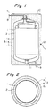
- Fig. 1 is a sectional view of a vacuum heat-insulating container of the present invention in the lengthwise direction.
- Fig. 2 is a sectional view of the same container in the crosswise (or diameter) direction.
- 1 is an inner container for storing a liquefied gas or the like of low temperature.
- inner container there can be used the same metallic container capable of maintaining vacuum, as used as an inner container in conventional vacuum heat-insulating containers.
- metal constituting the inner container stainless steel is preferably used generally. Its thickness can be varied depending upon the scale and the application purpose of the container but is usually about 2-3 mm.
- outside the inner container (1) is provided an outer container (3) via a vacuum heat-insulating layer (2).
- the space surrounded by the double wall of the inner container (1) and the outer container (3), i.e. the vacuum heat-insulating layer (2) is tightly sealed and separated from the outside air and maintained in a vacuum state.
- the vacuum heat-insulating container of the present invention is intended to have a small weight by making the outer container (3) lightweight. Therefore, the outer container consists of an inner side membrane (4), an outer surface material (6) and a rigid plastic foam (5) placed in the gap between them, as shown in Figs. 1 and 2.
- the inner side membrane (4) which comes in contact with the vacuum heat-insulating layer (2), is not required to have a high mechanical strength if it has tightness sufficient to maintain the vacuum heat-insulating layer in a vacuum state, and is not required to have by itself a strength capable of withstanding the vacuum pressure applied to the vacuum heat-insulating layer.
- the inner side membrane (4) is desired to be as thin and lightweight as possible as long as the desired vacuum of the vacuum heat-insulating layer is maintained, and there can be preferably used a metal membrane of generally 0.05-1 mm, preferably 0.1-0.5 mm in thickness.
- the material for the metal membrane there can be mentioned, for example, stainless steel, aluminum, duralumin, copper and nickel. Of these, stainless steel is preferable.
- a metal membrane which is weldable is advantageous for the processing standpoint.
- the rigid plastic foam is preferably formed by in situ foaming of pourable or injectionable, foamable liquid.
- the rigid plastic foam there can be mentioned, for example, a rigid polyurethane foam, a polyisocyanurate foam and a phenolic resin foam. Of these, a rigid polyurethane foam is particularly preferable.
- the rigid polyurethane foam can be any ordinary polyurethane foam conventionally used in heat-insulating material applications.
- the rigid plastic foam (5) is required to have a sufficient adhesion strength to the inner side membrane (4) so that the membrane is not peeled from the plastic foam by the suction of the vacuum pressure applied to the vacuum heat-insulating layer.
- a foamed in place rigid polyurethane foam however, it self-adheres to the inner side membrane simultaneously with the foaming of polyurethane, producing a sufficient adhesion strength.
- the rigid plastic foam (5) is required to have a strength sufficient for protecting the outer container including plastic foam from being deformed or broken by the vacuum pressure of the vacuum heat-insulating layer (2).
- the rigid plastic foam (5) is required to have a compression strength of 7.848 bar (8 kg/cm2)or more when, for example, a rigid urethane foam (5) of 30 mm in thickness is formed on the outer surface of an inner side membrane (4) of 400 mm in diameter.
- the compression strength varies depending upon the size of the container and the thickness of the rigid plastic foam.
- a rigid plastic foam having a desired compression strength can be easily obtained by those skilled in the art, by empirically selecting, for example, the density of rigid plastic foam.
- the rigid plastic foam (5) has advantages of not only supporting the inner side membrane (4) but also, when the vacuum of the vacuum heat-insulating layer (2) has been lost or reduced, preventing the rapid gasification of the contents stored in the vacuum heat-insulating container of the present invention owing to the excellent heat-insulating effect of the rigid plastic foam itself.
- an outer surface material (6) Outside the rigid plastic foam (5) is provided an outer surface material (6).
- the outer container (3) comes to have a sandwich structure consisting of an inner side membrane (4), a rigid plastic foam (5) and an outer surface material (6) and thereby can have an increased strength.
- the outer surface material (6) serves also as a protecting or coating material for the rigid plastic foam (5).
- the outer surface material there can be used, for example, a FRP plate, a plastic plate and a metal plate (e.g. colored iron plate, colored aluminum plate). In the case of a FRP plate, there can be preferably used a plate of generally about 1-3 mm in thickness.
- the vacuum heat-insulating container of the present invention having the above constitution can be produced as follows, for example.
- the membrane (4) is provided with a pipe (9) for making the vacuum heat-insulating layer (2) vacuum (see Fig. 1).
- the thus formed inner container-membrane assembly is set in a mold together with an outer surface material (6) while a given space for allowing foaming therein is secured between the assembly and the outer surface material.
- a starting foamable liquid for plastic foam is poured or injected into the space through an injection hole (10) (see Fig. 1).
- the poured or injected starting foamable liquid for plastic foam causes foaming, whereby the space is filled and a plastic foam layer is formed.
- the space for vacuum heat-insulating layer (2), provided between the inner container (1) and the membrane (4) is pressurized by a gas (e.g. air) fedthrough the pipe (9) for achieving vacuum.
- This pressurization can be effected by a pressure of 0.0981-1.962 bar (0.1-0.2 kg/cm2)before the pouring or injection, in order to retain the shape of the membrane.
- the pressure inside the space is desirably kept constantly higher by about 0.0981-0.4905 bar (0.1-0.5 kg/cm2) than the pressure of foaming, by, for example, measuring the pressure applied to the inner surface of the outer surface material (6), i.e. the foaming pressure by means of a pressure gauge or pressure sensor (12) (see Fig. 1) provided in the outer surface material.
- the pressure control can be effected manually while watching the pressure gauge, or automatically by electric conversion of the foaming pressure detected.
- the amount of the starting foamable liquid to be poured or injected can be calculated from the volume of space to be occupied by plastic foam and the density of desired plastic foam.
- the foaming and hardening of the starting foamable liquid poured or injected can be effected usually at room temperature.
- the foaming and/or the hardening may be accelerated by heating the container to which the starting foamable liquid is poured or injected, to a temperature up to about 60°C.
- a 30-liter container made of stainless steel SUS 304 and having a diameter of 300 mm, a height of 460 mm and a thickness of 2.0 mm
- a membrane a membrane (weight: 2.6 kg) made of stainless steel SUS 304 and having a thickness of 0.3 mm
- a FRP plate weight: 2.0 kg having a thickness of 2.0 mm.
- a starting foamable liquid to become a rigid urethane foam having a density of 0.1 g/cm3 and a compression strength of 10.791 bar (11 kg/cm2) in a filled state was poured into the plastic foam layer at room temperature and allowed to foam and harden, whereby the plastic foam layer was filled.
- the amount of the starting foamable liquid poured was 3.0 kg.
- the air pressure of the space for vacuum heat-Insulating layer was 0.0981-0.1962 bar (0.1-0.2 kg/cm2) before pouring and, during the period from the pouring to the completion of hardening, was kept higher by 0.0981 bar (0.1 kg/cm2) than the pressure of foaming by manual operation of a pressure gauge while watching the foaming pressure indicated by a pressure gauge.
- the highest foaming pressure was 0.6867 bar (0.7 kg/cm2). After the completion of the foaming, the system was allowed to stand and cooled to room temperature. When a liquefied natural gas (LNG) was stored in the resulting vacuum heat-insulating container, the container showed good performance.
- LNG liquefied natural gas
- a conventional type container was prepared using the same inner container and vacuum heat-insulating layer as in Example and, as an outer container, stainless steel SUS 304 (weight: 20 kg) having a thickness of 2.3 mm.
- a radial shield (1.5 kg) and a heat-insulating support (1.0 kg) were used in each of the vacuum heat-insulating layers of Example and Comparative Example.
- the vacuum heat-insulating container of the present invention has, as its outer container, a sandwich structure consisting of an inner side membrane capable of maintaining vacuum, a rigid plastic foam and an outer surface material and accordingly is lightweight, and yet has a sufficient strength and can maintain vacuum well.
- the weight of the outer container can be made significantly light, as compared with those of conventional containers made of a metal. Therefore, the vacuum heat-insulating container of the present invention is most suitable also as a vacuum heat-insulating container to be mounted on vehicles.
Landscapes
- Engineering & Computer Science (AREA)
- Mechanical Engineering (AREA)
- Physics & Mathematics (AREA)
- Thermal Sciences (AREA)
- General Engineering & Computer Science (AREA)
- Packages (AREA)
- Laminated Bodies (AREA)
- Thermal Insulation (AREA)
- Filling Or Discharging Of Gas Storage Vessels (AREA)
- Thermally Insulated Containers For Foods (AREA)
- Casting Or Compression Moulding Of Plastics Or The Like (AREA)
- Molding Of Porous Articles (AREA)
Claims (4)
- Réservoir isolé sous vide contre la chaleur constitué d'une structure à double paroi composée d'un réservoir intérieur (1) et d'un réservoir extérieur (3), un vide étant créé dans l'espace (2) compris entre le réservoir intérieur (1) et le réservoir extérieur (3), réservoir isolé sous vide contre la chaleur dans lequel le réservoir extérieur (3) a une structure composite comprenant un matériau de surface extérieur (6), un matériau de surface latérale intérieur (4) capable d'entretenir le vide, et une matière plastique mousse (5) placée dans l'espace entre le matériau de surface extérieur et le matériau de surface latérale intérieur (4),
caractérisé en ce que(a) ladite matière plastique mousse (5) est une matière plastique mousse (5) rigide ayant une résistance à la compression d'au moins 7.848 bar (8 kg/cm²);(b) ladite structure composite du réservoir extérieur (3) est une structure en sandwich (4, 5, 6) composée dudit matériau de surface extérieur (6), dudit matériau de surface latérale intérieur (4) et de ladite matière plastique mousse (5) rigide; et(c) ledit matériau de surface latérale intérieur (4) se présente sous la forme d'une membrane latérale intérieure (4). - Réservoir selon la revendication 1, caractérisé en ce que la membrane latérale intérieure (4) capable d'entretenir le vide est une membrane métallique (4) de 0.05-1.0 mm d'épaisseur, qui peut être soudée.
- Réservoir selon la revendication 1, caractérisé en ce que la membrane métallique (4) est en acier inoxydable.
- Réservoir selon la revendication 1, caractérisé en ce que la matière plastique mousse (5) est de la mousse rigide de polyuréthane.
Applications Claiming Priority (2)
| Application Number | Priority Date | Filing Date | Title |
|---|---|---|---|
| JP3396/90 | 1990-01-12 | ||
| JP2003396A JPH03208611A (ja) | 1990-01-12 | 1990-01-12 | 真空断熱容器及びその製法 |
Publications (2)
| Publication Number | Publication Date |
|---|---|
| EP0440031A1 EP0440031A1 (fr) | 1991-08-07 |
| EP0440031B1 true EP0440031B1 (fr) | 1994-11-30 |
Family
ID=11556201
Family Applications (1)
| Application Number | Title | Priority Date | Filing Date |
|---|---|---|---|
| EP91100330A Expired - Lifetime EP0440031B1 (fr) | 1990-01-12 | 1991-01-11 | Réservoir isolé sous vide contre la chaleur |
Country Status (3)
| Country | Link |
|---|---|
| EP (1) | EP0440031B1 (fr) |
| JP (1) | JPH03208611A (fr) |
| DE (1) | DE69105285T2 (fr) |
Families Citing this family (10)
| Publication number | Priority date | Publication date | Assignee | Title |
|---|---|---|---|---|
| DE4330005A1 (de) * | 1993-09-04 | 1995-03-09 | Jacobs Suchard Ag | Vorrichtung zur Aufnahme und Abgabe von Flüssigkeiten |
| KR100400148B1 (ko) * | 1995-04-13 | 2004-04-21 | 헌트스만 인터내셔날, 엘엘씨 | 비평면탈기절연패널및그의제조방법 |
| PL1612468T3 (pl) * | 2004-07-02 | 2007-07-31 | Brugg Rohr Ag Holding | Rura przewodowa |
| KR101865210B1 (ko) * | 2013-06-21 | 2018-06-07 | 카와사키 주코교 카부시키 카이샤 | 액화 가스 저장 탱크 및 액화 가스 운반선 |
| CN104712899B (zh) * | 2013-12-13 | 2017-11-03 | 南京航空航天大学 | 一种真空绝热板保温的深冷液体储运罐 |
| CN104358999B (zh) * | 2014-11-07 | 2017-07-04 | 宜昌江峡船用机械有限责任公司 | 珠光砂夹层低温容器加热抽真空装置及方法 |
| WO2016097461A1 (fr) * | 2014-12-16 | 2016-06-23 | Wärtsilä Finland Oy | Réservoir de gaz naturel liquéfié |
| JP7296116B2 (ja) * | 2019-10-04 | 2023-06-22 | 国立研究開発法人宇宙航空研究開発機構 | 保温保冷装置 |
| CN113459378B (zh) * | 2020-03-30 | 2022-12-16 | 青岛海尔电冰箱有限公司 | 冰保温箱体及其制备方法及具有其的冰箱 |
| CN111750265B (zh) * | 2020-05-15 | 2021-10-15 | 刘济华 | 一种低温液态气体储存瓶 |
Family Cites Families (3)
| Publication number | Priority date | Publication date | Assignee | Title |
|---|---|---|---|---|
| FR1273907A (fr) * | 1960-09-03 | 1961-10-20 | Réservoir de stockage et de transport de gaz liquéfiés | |
| GB1403771A (en) * | 1972-01-10 | 1975-08-28 | Imi Santon Ltd | Thermally insulated containers |
| FR2352717A1 (fr) * | 1976-02-06 | 1977-12-23 | Delaunay Philippe | Protection mecanique du vase dewar |
-
1990
- 1990-01-12 JP JP2003396A patent/JPH03208611A/ja active Pending
-
1991
- 1991-01-11 EP EP91100330A patent/EP0440031B1/fr not_active Expired - Lifetime
- 1991-01-11 DE DE69105285T patent/DE69105285T2/de not_active Expired - Fee Related
Also Published As
| Publication number | Publication date |
|---|---|
| JPH03208611A (ja) | 1991-09-11 |
| DE69105285D1 (de) | 1995-01-12 |
| EP0440031A1 (fr) | 1991-08-07 |
| DE69105285T2 (de) | 1995-04-06 |
Similar Documents
| Publication | Publication Date | Title |
|---|---|---|
| US5797513A (en) | Insulated vessels | |
| US4155482A (en) | Insulated cryogenic liquid container | |
| US5419139A (en) | Composite cryogenic tank apparatus | |
| US3440308A (en) | Method of making a refrigerator cabinet assembly | |
| EP0457787B2 (fr) | Enveloppe d'isolation thermique | |
| EP0440031A1 (fr) | Réservoir isolé sous vide contre la chaleur | |
| US20090223974A1 (en) | Container for storing liquefied gas | |
| US3485409A (en) | Tankship container for liquefied gas | |
| EP2812624A1 (fr) | Conteneur-citerne pour le transport et le stockage de gaz liquéfiés cryogéniques | |
| CA1045061A (fr) | Cuve isolee | |
| JP3428748B2 (ja) | 液体運搬船用自立角型タンク | |
| US3754675A (en) | Low-temperature liquefied-gas storage reservoir | |
| US3379330A (en) | Cryogenic insulation system | |
| US5439945A (en) | Foams produced under reduced pressure and method of preparing such foams | |
| KR20160067899A (ko) | 유체 저장 탱크의 단열을 위한 자력 지지 케이스 및 그 케이스의 제조 방법 | |
| CN114211776B (zh) | 一种碳纤维支架复合成型的制造方法 | |
| AU596216B2 (en) | Isothermal structure | |
| US3224623A (en) | Liquefied gas container insulation | |
| KR101434150B1 (ko) | 복합재료 보강재의 제조방법 | |
| JP2809356B2 (ja) | 超低温貨物格納用タンクの真空式断熱パネル | |
| US3802948A (en) | Thermal insulation for cryogenic containers | |
| EP0945666B1 (fr) | Méthode de fabrication d'un support isolé thermiquement | |
| EP0733330A1 (fr) | Récipient isolant en résine synthétique et méthode pour fabriquer un tel récipient | |
| JPH08100991A (ja) | 断熱パネルの製造方法 | |
| JP3396591B2 (ja) | 断熱支持装置の製造方法 |
Legal Events
| Date | Code | Title | Description |
|---|---|---|---|
| PUAI | Public reference made under article 153(3) epc to a published international application that has entered the european phase |
Free format text: ORIGINAL CODE: 0009012 |
|
| AK | Designated contracting states |
Kind code of ref document: A1 Designated state(s): DE FR GB |
|
| 17P | Request for examination filed |
Effective date: 19920129 |
|
| 17Q | First examination report despatched |
Effective date: 19930426 |
|
| GRAA | (expected) grant |
Free format text: ORIGINAL CODE: 0009210 |
|
| AK | Designated contracting states |
Kind code of ref document: B1 Designated state(s): DE FR GB |
|
| REF | Corresponds to: |
Ref document number: 69105285 Country of ref document: DE Date of ref document: 19950112 |
|
| ET | Fr: translation filed | ||
| PLBE | No opposition filed within time limit |
Free format text: ORIGINAL CODE: 0009261 |
|
| STAA | Information on the status of an ep patent application or granted ep patent |
Free format text: STATUS: NO OPPOSITION FILED WITHIN TIME LIMIT |
|
| 26N | No opposition filed | ||
| PGFP | Annual fee paid to national office [announced via postgrant information from national office to epo] |
Ref country code: GB Payment date: 19980102 Year of fee payment: 8 |
|
| PGFP | Annual fee paid to national office [announced via postgrant information from national office to epo] |
Ref country code: DE Payment date: 19980112 Year of fee payment: 8 |
|
| PGFP | Annual fee paid to national office [announced via postgrant information from national office to epo] |
Ref country code: FR Payment date: 19980129 Year of fee payment: 8 |
|
| PG25 | Lapsed in a contracting state [announced via postgrant information from national office to epo] |
Ref country code: GB Free format text: LAPSE BECAUSE OF NON-PAYMENT OF DUE FEES Effective date: 19990111 |
|
| GBPC | Gb: european patent ceased through non-payment of renewal fee |
Effective date: 19990111 |
|
| PG25 | Lapsed in a contracting state [announced via postgrant information from national office to epo] |
Ref country code: FR Free format text: LAPSE BECAUSE OF NON-PAYMENT OF DUE FEES Effective date: 19990930 |
|
| PG25 | Lapsed in a contracting state [announced via postgrant information from national office to epo] |
Ref country code: DE Free format text: LAPSE BECAUSE OF NON-PAYMENT OF DUE FEES Effective date: 19991103 |
|
| REG | Reference to a national code |
Ref country code: FR Ref legal event code: ST |