EP0440090A1 - Hotte d'aspiration pour des gaz nuisibles - Google Patents
Hotte d'aspiration pour des gaz nuisibles Download PDFInfo
- Publication number
- EP0440090A1 EP0440090A1 EP91100905A EP91100905A EP0440090A1 EP 0440090 A1 EP0440090 A1 EP 0440090A1 EP 91100905 A EP91100905 A EP 91100905A EP 91100905 A EP91100905 A EP 91100905A EP 0440090 A1 EP0440090 A1 EP 0440090A1
- Authority
- EP
- European Patent Office
- Prior art keywords
- wall
- suction hood
- elements
- positions
- movable
- Prior art date
- Legal status (The legal status is an assumption and is not a legal conclusion. Google has not performed a legal analysis and makes no representation as to the accuracy of the status listed.)
- Granted
Links
- 239000007789 gas Substances 0.000 title claims abstract description 28
- 230000000266 injurious effect Effects 0.000 title claims abstract description 16
- 238000000605 extraction Methods 0.000 claims abstract description 10
- 239000003517 fume Substances 0.000 claims abstract description 5
- 239000004033 plastic Substances 0.000 claims description 8
- 230000007423 decrease Effects 0.000 claims 1
- 230000008878 coupling Effects 0.000 description 4
- 238000010168 coupling process Methods 0.000 description 4
- 238000005859 coupling reaction Methods 0.000 description 4
- 238000006073 displacement reaction Methods 0.000 description 2
- 230000000694 effects Effects 0.000 description 2
- VOXZDWNPVJITMN-ZBRFXRBCSA-N 17β-estradiol Chemical compound OC1=CC=C2[C@H]3CC[C@](C)([C@H](CC4)O)[C@@H]4[C@@H]3CCC2=C1 VOXZDWNPVJITMN-ZBRFXRBCSA-N 0.000 description 1
- 239000003779 heat-resistant material Substances 0.000 description 1
- 239000000463 material Substances 0.000 description 1
- 239000002985 plastic film Substances 0.000 description 1
Images


Classifications
-
- B—PERFORMING OPERATIONS; TRANSPORTING
- B08—CLEANING
- B08B—CLEANING IN GENERAL; PREVENTION OF FOULING IN GENERAL
- B08B15/00—Preventing escape of dirt or fumes from the area where they are produced; Collecting or removing dirt or fumes from that area
- B08B15/02—Preventing escape of dirt or fumes from the area where they are produced; Collecting or removing dirt or fumes from that area using chambers or hoods covering the area
Definitions
- the present invention relates to a suction hood for extraction of injurious gases, said suction hood being connected to a gas extraction system and preferably suspended on a movable arm system permitting the suction hood to be set in various positions relative to an area from which the injurious gases are extracted.
- Suction hoods of the above type are already known from e.g. DK 143 538 and SE 8702139-0 and they are distinguished by their slenderness and by the fact that they are not especially deep such that they can be put, leaned or placed at a suitable spot for not being in the way during work and for quick displacement if necessary.
- These prior art suction hoods can not be used however, if a suction hood with a great depth is required or if a slender suction hood temporarily must be "transformed” into a suction hood with great depth.
- the object of the present invention is therefore to provide a suction hood of a similar slender type as previously, but which also can be used when a suction hood with great depth is permanently or temporarily required. According to the invention this is arrived at by means of the characterizing features of claim 1.
- a suction hood with these features may be placed on a working surface when required and it is possible to work inside the suction hood, which means that issue of injurious gases into the premises is completely prevented; in many instances a condition for being able to carry out certain jobs.
- the suction hood is quickly and by simple manupulations "transformed” into a “slender type" which is easy to handle and in many cases has sufficient suction capacity.
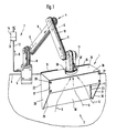
- the suction hood 1 illustrated in the drawings is adapted for extracting injurious gases G from an area 2 wherein such gases are generated.
- the suction hood is provided on a working table 3 through a movable arm system 4 which is fixedly mounted on said working table 3 by means of a clampable bracket 5.
- the arm system 4 comprises a "suction arm" 6 forming part of a gas extraction system 7 and consisting of four hollow arm members 8-11, of which the first arm member 8 is connected to the bracket 5 and pivotable in relation thereto about a vertical axis.
- the arm member 8 is connected to the arm member 9 through a hollow coupling member and the arm member 9 is pivotable relative to the arm member 8 about a horizontal axis.
- the arm members 9. 10 and 11 are also connected to each other through hollow coupling members and they are pivotable relative to each other about horizontal axes.
- the gas extraction system 7 also includes a conduit 12 which connects the "suction arm" 6 to a fan 13 and a filter device 14.
- the fan 13 is adapted to generate a negative pressure in the gas extraction system and thus, a suction effect in the suction hood l.
- the gases G are cleaned in the filter device 14 and discharged to the surroundings in a cleaned state.
- the arm system 4 allows putting the suction hood 1 on the working table 3 as shown in fig. 1, but it also allows leaning the suction hood in a suitable manner (not shown) or turning and placing it lying on the working table 3 as is shown in fig. 5.
- the arm systen 4 also permits positioning of the suction hood 1 on many different spots on the working table and easy displacement thereof. Furthermore, the arm system 4 allows keeping the suction hood l set in a suitable position above the working table 3.
- the suction hood l has a depth d which is chosen such as to give the suction hood l a "slender" shape and in view of the suction effect which is normally required for sucking out injurious gases G.
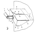
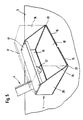
- the depth d of the suction hood l is in certain cases not sufficient and therefore, said suction hood is provided with three movably mounted wall elements 15, 16 and 17 which can be set in folded positions (see figs. 1 and 2) and which are movable to unfolded positions (see figs. 3 and 4) for "increasing" the depth of the suction hood from the depth d to the depth D and thus, giving the suction hood a fume cupboard like shape and function.
- the suction hood l After unfolding the wall elements 15, 16, 17 to the unfolded positions, the suction hood l allows for carrying out the gas generating work inside the suction hood l, whereby it is ensured that no injurious gases are issued into the premises. After finishing such work, the movable wall elements 15, 16, 17 may be moved back to their folded positions, whereby the suction hood l regains its "slender" shape.
- the suction hood l on which the wall elements 15, 16, 17 are movably mounted consists of a rear wall 18, a top wall 19 protruding forward from the rear wall and two end walls 20, 21 also protruding forward from the rear wall.
- These walls 18-21 define a "box" which is open in forward-downward direction and which can be kept suspended in various positions of the arm system 4 or placed standing in various positions on the working table 3.
- the movable wall element 15 is mounted at the rear edge 22 of the end wall 20 through a flexible portion which provides a "hinge function" such that the wall element 15 is movable from a folded position wherein it extends along the rear wall 18 (see figs. 1 and 2) to an unfolded position in which it extends in forward direction along the end wall 20 and a distance beyond the front edges of said end wall 21 (see figs. 3 and 4).
- the movable wall element 16 is mounted at the rear edge 23 of the end wall 21 through a flexible portion which provides a "hinge function" such that the wall element 16 is movable from a folded position wherein it extends along the rear wall 18 (see figs. 1 and 2) to an unfolded position in which it extends in forward direction along the end wall 21 and a distance beyond the front edges of said end wall 21.
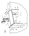
- the movably mounted wall elements 15, 16 preferably have substantially the same height as the rear wall 18 and a width B which is only somewhat smaller than half the length L of said rear wall 18.
- Each wall element 15, 16 also have somewhat protruding handle portions 24, 25 and preferably snap portions (not shown) permitting locking of said handle portions onto the rear wall 18.
- the movable wall element 17 is mounted on the front edge 26 of the top wall 19 through a flexible portion providing a "hinge function" such that the wall element 17 is movable from a folded position wherein it extends downwards from the top wall 19 and engages those front edges 27, 28 of the end walls 20, 21 which extend downwards parallel to the rear wall 18.
- the wall element 17 is preferably lockable in this position onto the end walls 20, 21 through suitable snap means.
- the wall element 17 is unfoldable (hinged) and in unfolded position positionable on obliquely directed edge portions 29, 30 of the wall elements 15, 16. Furthermore, all three wall elements 15, 16, 17 have coupling portions so as to interconnect the wall elements in their unfolded positions, whereby said wall elements retain each other in these positions.
- the coupling portions may preferably consist of upwardly directed pegs 31 on the wall elements 15, 16 and holes therefor in the wall element 17. In its unfolded position, the front edge 33 of the wall element 17 preferably extends in substantially the same vertical plane as the vertical front edges 34, 35 or the wall elements 15, 16.
- the arm system 4 also permits positioning of the suction hood 1 lying with the rear wall 18 as the bottom in a box like unit (see fig. 5), wherein the wall elements 15, 16, 17 are directed upwards instead of in forward direction when in unfolded positions (see the dashed and dotted lines in fig. 5).
- This position of the suction hood l may be of interest particularly if the rear wall 18 is made of heat resistant material, e.g. if it consists of a planar sheet, since such a rear wall 18 can be used for placing hot workpieces thereon.
- the rear wall of the suction hood l may consist of a sheet, while the remaining parts thereof are made of a plastic billet 36 to be further described below.
- the top wall 19 of the suction hood 1 preferably has an aperture 37 which is adapted to direct gases from the suction hood l into the suction arm 6.
- the top wall 19 preferably has a collar 38 (which may consist of one or more sections) and two hooks 39, 40.
- the collar 38 fits onto an end portion of the arm member 11 and the suction hood 1 may be fastened thereto by threading the collar 38 thereof onto said end portion until the hooks 39, 40 lock the suction hood 1 at the arm member 11.
- the suction hood l may, when required, pivot relative to the arm member 11, which is advantageous while the setting possibilities thereof is thereby increased.
- the plastic billet 36 is shown in fig. 6 and comprises a substantially planar plastic sheet from which the collar 38 and hooks 39, 40 protrude from that portion, which will define the top wall 19 Double rows of longitudinal ribs 41, defining grooves 42 in which the rear wall 18 is fastenable, protrude from portions at the rear edges or the top wall 19 and end walls 20, 21.
- the plastic billet 36 includes portions which will define the end walls 20, 21. Along a longer side of those portions which define the top wall 19, a portion extends which will define the wall element 17. At rear edges of those members defining the end walls 20, 21, portions extend which will define the wall elements 15, 16. Along the separating lines between the portions defining the top wall 19 and the portions defining the wall element 17, the thickness of the plastic material is preferably reduced to permit a hinge function between these portions. This is preferably also the case for the separating lines between the end walls 20, 21 and the wall elements 15, 16.
- the movable wall elements 15, 16, 17 of the suction hood 1 described above and shown in the drawings, do not need to be unfolded simultaneously; in certain cases it can be appropriate to unfold only one or two of the wall elements 15, 16, 17.
- suction hood with one, two, four or more movably mounted wall elements instead of three such wall elements, or a suction hood with expandable or telescopic or otherwise movably mounted wall elements instead of pivotally mounted elements.
- the movable wall elements at the end walls may alternatively be mounted at the front edges of the end walls instead of at their rear edges and the wall element or elements may be fixed in their various positions in other ways and by other means than shown.
- the wall element or elements may have another suitable size than described and parts of the suction hood may be manufactured in another way than by folding a plastic billet.
- the injurious gases are directed from the suction hood 1 through the "suction arm" 6, which defines the movable arm system 4 as well as the gas conduct.
- the arm system 4 comprises pivotally connected arms on which hoses and/or tubes are suspended for directing the injurious gases from the suction hood.
- the suction hood is preferably but not necessarily mounted on an arm system.
- the suction hood 1 can be freely arranged on a working table or at another suitable spot with or without support means and the suction hood may in this case be connected to a flexible hose or a flexible tube which does not support the suction hood but merely is adapted to discharge the injurious gases therefrom.
Landscapes
- Ventilation (AREA)
- Prevention Of Fouling (AREA)
- Sampling And Sample Adjustment (AREA)
- Separation Of Particles Using Liquids (AREA)
- Devices For Use In Laboratory Experiments (AREA)
Applications Claiming Priority (2)
| Application Number | Priority Date | Filing Date | Title |
|---|---|---|---|
| SE9000322 | 1990-01-31 | ||
| SE9000322A SE470126B (sv) | 1990-01-31 | 1990-01-31 | Sughuv, omformbar till dragskåpsliknande form och funktion |
Publications (2)
| Publication Number | Publication Date |
|---|---|
| EP0440090A1 true EP0440090A1 (fr) | 1991-08-07 |
| EP0440090B1 EP0440090B1 (fr) | 1995-04-05 |
Family
ID=20378398
Family Applications (1)
| Application Number | Title | Priority Date | Filing Date |
|---|---|---|---|
| EP91100905A Expired - Lifetime EP0440090B1 (fr) | 1990-01-31 | 1991-01-24 | Hotte d'aspiration pour des gaz nuisibles |
Country Status (7)
| Country | Link |
|---|---|
| US (1) | US5133691A (fr) |
| EP (1) | EP0440090B1 (fr) |
| JP (1) | JPH04215857A (fr) |
| AT (1) | ATE120671T1 (fr) |
| CA (1) | CA2035387A1 (fr) |
| DE (1) | DE69108578T2 (fr) |
| SE (1) | SE470126B (fr) |
Cited By (2)
| Publication number | Priority date | Publication date | Assignee | Title |
|---|---|---|---|---|
| EP2255898A1 (fr) * | 2009-05-29 | 2010-12-01 | Hakko Corporation | Unité d'aspiration de la fumée |
| US8556570B2 (en) | 2009-05-29 | 2013-10-15 | Hakko Corporation | Smoke and fume removal assembly with dual suction modes |
Families Citing this family (16)
| Publication number | Priority date | Publication date | Assignee | Title |
|---|---|---|---|---|
| US5398978A (en) * | 1993-12-02 | 1995-03-21 | Henlex Inc. | Adjustable coupling for linking conduits |
| DE19801316A1 (de) * | 1998-01-15 | 1999-07-22 | Kaltenbach & Voigt | Medizinischer oder dentaltechnischer Arbeitstisch |
| US6821200B2 (en) * | 2002-03-27 | 2004-11-23 | Edward Alan Chilcoat | Low-cost/disposable hazardous material handling and anti-contamination hoods |
| TW525765U (en) * | 2002-06-14 | 2003-03-21 | Inst Of Occupational Safety & Health Council Of Labor Affairs | Airflow capture booth with single-plate windbreak |
| RU2280818C2 (ru) * | 2004-08-05 | 2006-07-27 | Новосибирский государственный архитектурно-строительный университет (Сибстрин) | Защитное вытяжное вентиляционное устройство |
| US20100267321A1 (en) * | 2007-06-22 | 2010-10-21 | Institute Of Occupational Safety And Health, Council Of Labor Affairs, Executive Yuan | Air curtain-isolated biosafety cabinet |
| US20090038104A1 (en) * | 2007-08-08 | 2009-02-12 | Hsu Hsiu-Kwei Liu | Bench-top chip removing vacuum hood |
| RU2403504C2 (ru) * | 2008-07-31 | 2010-11-10 | Государственное образовательное учреждение высшего профессионального образования Новосибирский государственный архитектурно-строительный университет (Сибстрин) | Вытяжное защитное вентиляционное устройство |
| RU2440174C2 (ru) * | 2009-08-26 | 2012-01-20 | Общество с ограниченной ответственностью "Проектно-технологическое бюро проектно-строительного объединения Волгоградгражданстрой" | Установка для улавливания и очистки газовых выбросов от технологического оборудования |
| CN102950136A (zh) * | 2012-11-09 | 2013-03-06 | 大连海顺重工环保设备有限公司 | 一种半伸缩式烟气捕集罩 |
| JP6349005B1 (ja) * | 2017-04-04 | 2018-06-27 | 日本エアーテック株式会社 | ドラフト装置 |
| US11318509B2 (en) * | 2017-11-06 | 2022-05-03 | Air Systems Design, Inc. | Dust hood |
| DE102018210433A1 (de) * | 2018-06-26 | 2020-01-02 | Dürr Systems Ag | Trennvorrichtung und Behandlungsanlage |
| CN109750783A (zh) * | 2018-12-29 | 2019-05-14 | 天津永利达盛实验室设备有限公司 | 一种理化生实验室综合吊装系统 |
| RU2722712C1 (ru) * | 2019-07-23 | 2020-06-03 | Павел Геннадьевич Владимиров | Устройство для очистки воздуха в рабочей зоне мастера ногтевого сервиса |
| EP4027061A1 (fr) * | 2021-01-12 | 2022-07-13 | Electrolux Appliances Aktiebolag | Dispositif d'extraction pour l'élimination d'air, appareil combiné et bras d'aspiration |
Citations (1)
| Publication number | Priority date | Publication date | Assignee | Title |
|---|---|---|---|---|
| FR2334432A1 (fr) * | 1975-11-17 | 1977-07-08 | Barbieri Galdino | Hotte d'aspiration |
Family Cites Families (6)
| Publication number | Priority date | Publication date | Assignee | Title |
|---|---|---|---|---|
| US398968A (en) * | 1889-03-05 | George l | ||
| US380500A (en) * | 1888-04-03 | Cook-stove ventilator | ||
| US404194A (en) * | 1888-06-20 | 1889-05-28 | Odor-preventing device for cooking-stoves | |
| US2905073A (en) * | 1956-02-09 | 1959-09-22 | Aveni Anthony | Collapsible hood |
| US3082680A (en) * | 1961-02-06 | 1963-03-26 | Bakers Pride Oven Co Inc | Smoke hood |
| US3520115A (en) * | 1968-06-24 | 1970-07-14 | American Air Filter Co | Collapsible hood assembly |
-
1990
- 1990-01-31 SE SE9000322A patent/SE470126B/sv not_active IP Right Cessation
-
1991
- 1991-01-24 AT AT91100905T patent/ATE120671T1/de not_active IP Right Cessation
- 1991-01-24 DE DE69108578T patent/DE69108578T2/de not_active Expired - Fee Related
- 1991-01-24 EP EP91100905A patent/EP0440090B1/fr not_active Expired - Lifetime
- 1991-01-25 JP JP3007717A patent/JPH04215857A/ja active Pending
- 1991-01-30 US US07/647,841 patent/US5133691A/en not_active Expired - Fee Related
- 1991-01-31 CA CA002035387A patent/CA2035387A1/fr not_active Abandoned
Patent Citations (1)
| Publication number | Priority date | Publication date | Assignee | Title |
|---|---|---|---|---|
| FR2334432A1 (fr) * | 1975-11-17 | 1977-07-08 | Barbieri Galdino | Hotte d'aspiration |
Non-Patent Citations (1)
| Title |
|---|
| Soviet Inventions Illustrated, P section, week K 06, March 23, 1983, Derwent Publications Ltd., London, P 43; & SU-A-916 913 (GORKI CAR WKS). * |
Cited By (2)
| Publication number | Priority date | Publication date | Assignee | Title |
|---|---|---|---|---|
| EP2255898A1 (fr) * | 2009-05-29 | 2010-12-01 | Hakko Corporation | Unité d'aspiration de la fumée |
| US8556570B2 (en) | 2009-05-29 | 2013-10-15 | Hakko Corporation | Smoke and fume removal assembly with dual suction modes |
Also Published As
| Publication number | Publication date |
|---|---|
| SE9000322L (sv) | 1991-08-01 |
| SE470126B (sv) | 1993-11-15 |
| ATE120671T1 (de) | 1995-04-15 |
| DE69108578T2 (de) | 1995-12-14 |
| US5133691A (en) | 1992-07-28 |
| EP0440090B1 (fr) | 1995-04-05 |
| CA2035387A1 (fr) | 1991-08-01 |
| SE9000322D0 (sv) | 1990-01-31 |
| DE69108578D1 (de) | 1995-05-11 |
| JPH04215857A (ja) | 1992-08-06 |
Similar Documents
| Publication | Publication Date | Title |
|---|---|---|
| EP0440090A1 (fr) | Hotte d'aspiration pour des gaz nuisibles | |
| US5542359A (en) | Collapsible fish cleaning table | |
| US7040239B2 (en) | Downdraft table | |
| US3145966A (en) | Portable easel | |
| US6866035B2 (en) | Freestanding portable splatter shield | |
| SE441659B (sv) | Berbar och hopfellbar arbetsbenk | |
| US7188636B1 (en) | Containment cart | |
| DE4322662C2 (de) | Dunstabzugshaubenanordnung | |
| US9267291B1 (en) | Air blower device for cleaning a rain gutter and other elevated surfaces | |
| WO2004012500B1 (fr) | Combine station de nettoyage de gibier, evier portatif et glaciere | |
| US20070095419A1 (en) | Leaf catcher | |
| CA2087474C (fr) | Ramasse-poussiere pour utilisation avec un aspirateur | |
| US4856435A (en) | Stowable work bench | |
| US5467842A (en) | Collapsible saw horse | |
| US6000158A (en) | Pull out ironing board | |
| US8225724B2 (en) | Folding workstation | |
| EP2070661B1 (fr) | Établis réglables pour outils électriques | |
| CA2193753C (fr) | Chevalet pliable pour artistes | |
| US20060243312A1 (en) | Collapsible enclosure for a machine tool | |
| US4602446A (en) | Portable ironing board | |
| US4824083A (en) | Work rest, as used in particular by dental technicians and goldsmiths | |
| US9949564B1 (en) | Ice fishing accessory support apparatus | |
| US5642951A (en) | Adjustable continuous feed printer paper collection device | |
| US20050247588A1 (en) | Roller seat, and carrier for a very-large-capacity tool and material holder also mountable atop a step ladder | |
| USD433761S (en) | A-frame tripod truss for a scaffold |
Legal Events
| Date | Code | Title | Description |
|---|---|---|---|
| PUAI | Public reference made under article 153(3) epc to a published international application that has entered the european phase |
Free format text: ORIGINAL CODE: 0009012 |
|
| AK | Designated contracting states |
Kind code of ref document: A1 Designated state(s): AT BE CH DE DK ES FR GB GR IT LI LU NL SE |
|
| 17P | Request for examination filed |
Effective date: 19920203 |
|
| 17Q | First examination report despatched |
Effective date: 19930810 |
|
| GRAA | (expected) grant |
Free format text: ORIGINAL CODE: 0009210 |
|
| AK | Designated contracting states |
Kind code of ref document: B1 Designated state(s): AT BE CH DE DK ES FR GB GR IT LI LU NL SE |
|
| PG25 | Lapsed in a contracting state [announced via postgrant information from national office to epo] |
Ref country code: IT Free format text: LAPSE BECAUSE OF FAILURE TO SUBMIT A TRANSLATION OF THE DESCRIPTION OR TO PAY THE FEE WITHIN THE PRE;WARNING: LAPSES OF ITALIAN PATENTS WITH EFFECTIVE DATE BEFORE 2007 MAY HAVE OCCURRED AT ANY TIME BEFORE 2007. THE CORRECT EFFECTIVE DATE MAY BE DIFFERENT FROM THE ONE RECORDED.SCRIBED TIME-LIMIT Effective date: 19950405 Ref country code: DK Effective date: 19950405 Ref country code: CH Effective date: 19950405 Ref country code: BE Effective date: 19950405 Ref country code: AT Effective date: 19950405 Ref country code: ES Free format text: THE PATENT HAS BEEN ANNULLED BY A DECISION OF A NATIONAL AUTHORITY Effective date: 19950405 Ref country code: LI Effective date: 19950405 Ref country code: NL Free format text: LAPSE BECAUSE OF FAILURE TO SUBMIT A TRANSLATION OF THE DESCRIPTION OR TO PAY THE FEE WITHIN THE PRESCRIBED TIME-LIMIT Effective date: 19950405 Ref country code: GR Free format text: LAPSE BECAUSE OF FAILURE TO SUBMIT A TRANSLATION OF THE DESCRIPTION OR TO PAY THE FEE WITHIN THE PRESCRIBED TIME-LIMIT Effective date: 19950405 |
|
| REF | Corresponds to: |
Ref document number: 120671 Country of ref document: AT Date of ref document: 19950415 Kind code of ref document: T |
|
| REF | Corresponds to: |
Ref document number: 69108578 Country of ref document: DE Date of ref document: 19950511 |
|
| PG25 | Lapsed in a contracting state [announced via postgrant information from national office to epo] |
Ref country code: SE Effective date: 19950705 |
|
| REG | Reference to a national code |
Ref country code: CH Ref legal event code: PL |
|
| ET | Fr: translation filed | ||
| NLV1 | Nl: lapsed or annulled due to failure to fulfill the requirements of art. 29p and 29m of the patents act | ||
| PG25 | Lapsed in a contracting state [announced via postgrant information from national office to epo] |
Ref country code: LU Free format text: LAPSE BECAUSE OF NON-PAYMENT OF DUE FEES Effective date: 19960131 |
|
| PLBE | No opposition filed within time limit |
Free format text: ORIGINAL CODE: 0009261 |
|
| STAA | Information on the status of an ep patent application or granted ep patent |
Free format text: STATUS: NO OPPOSITION FILED WITHIN TIME LIMIT |
|
| 26N | No opposition filed | ||
| PGFP | Annual fee paid to national office [announced via postgrant information from national office to epo] |
Ref country code: FR Payment date: 19971223 Year of fee payment: 8 |
|
| PGFP | Annual fee paid to national office [announced via postgrant information from national office to epo] |
Ref country code: GB Payment date: 19980112 Year of fee payment: 8 |
|
| PGFP | Annual fee paid to national office [announced via postgrant information from national office to epo] |
Ref country code: DE Payment date: 19980114 Year of fee payment: 8 |
|
| PG25 | Lapsed in a contracting state [announced via postgrant information from national office to epo] |
Ref country code: GB Free format text: LAPSE BECAUSE OF NON-PAYMENT OF DUE FEES Effective date: 19990124 |
|
| GBPC | Gb: european patent ceased through non-payment of renewal fee |
Effective date: 19990124 |
|
| PG25 | Lapsed in a contracting state [announced via postgrant information from national office to epo] |
Ref country code: FR Free format text: LAPSE BECAUSE OF NON-PAYMENT OF DUE FEES Effective date: 19990930 |
|
| PG25 | Lapsed in a contracting state [announced via postgrant information from national office to epo] |
Ref country code: DE Free format text: LAPSE BECAUSE OF NON-PAYMENT OF DUE FEES Effective date: 19991103 |
|
| REG | Reference to a national code |
Ref country code: FR Ref legal event code: ST |