EP0440136B1 - Flüssigkristallzusammensetzung und Vorrichtung die diese enthält - Google Patents
Flüssigkristallzusammensetzung und Vorrichtung die diese enthält Download PDFInfo
- Publication number
- EP0440136B1 EP0440136B1 EP91101076A EP91101076A EP0440136B1 EP 0440136 B1 EP0440136 B1 EP 0440136B1 EP 91101076 A EP91101076 A EP 91101076A EP 91101076 A EP91101076 A EP 91101076A EP 0440136 B1 EP0440136 B1 EP 0440136B1
- Authority
- EP
- European Patent Office
- Prior art keywords
- liquid crystal
- single bond
- iii
- group
- carbons
- Prior art date
- Legal status (The legal status is an assumption and is not a legal conclusion. Google has not performed a legal analysis and makes no representation as to the accuracy of the status listed.)
- Expired - Lifetime
Links
- 239000004973 liquid crystal related substance Substances 0.000 title claims abstract description 309
- 239000000203 mixture Substances 0.000 title claims abstract description 198
- 150000001875 compounds Chemical class 0.000 claims abstract description 135
- 125000000217 alkyl group Chemical group 0.000 claims abstract description 43
- 125000005843 halogen group Chemical group 0.000 claims abstract description 16
- 125000001424 substituent group Chemical group 0.000 claims abstract description 15
- 239000004990 Smectic liquid crystal Substances 0.000 claims abstract description 11
- 230000003287 optical effect Effects 0.000 claims description 49
- 239000007788 liquid Substances 0.000 claims description 18
- 239000000758 substrate Substances 0.000 claims description 11
- 125000004435 hydrogen atom Chemical group [H]* 0.000 claims description 8
- 125000003545 alkoxy group Chemical group 0.000 claims description 5
- 229910052799 carbon Inorganic materials 0.000 claims description 4
- 125000004432 carbon atom Chemical group C* 0.000 claims description 4
- 239000013078 crystal Substances 0.000 claims description 4
- 125000002496 methyl group Chemical group [H]C([H])([H])* 0.000 claims description 3
- 125000002023 trifluoromethyl group Chemical group FC(F)(F)* 0.000 claims description 3
- 238000000034 method Methods 0.000 description 96
- 230000004044 response Effects 0.000 description 88
- 239000005262 ferroelectric liquid crystals (FLCs) Substances 0.000 description 62
- 0 *c1ccc(*)cc1 Chemical compound *c1ccc(*)cc1 0.000 description 55
- 230000000052 comparative effect Effects 0.000 description 52
- 230000007547 defect Effects 0.000 description 45
- 239000010410 layer Substances 0.000 description 26
- 230000005684 electric field Effects 0.000 description 25
- UHOVQNZJYSORNB-UHFFFAOYSA-N Benzene Chemical compound C1=CC=CC=C1 UHOVQNZJYSORNB-UHFFFAOYSA-N 0.000 description 23
- 239000011324 bead Substances 0.000 description 19
- 125000006850 spacer group Chemical group 0.000 description 19
- YXFVVABEGXRONW-UHFFFAOYSA-N Toluene Chemical compound CC1=CC=CC=C1 YXFVVABEGXRONW-UHFFFAOYSA-N 0.000 description 18
- PNEYBMLMFCGWSK-UHFFFAOYSA-N aluminium oxide Inorganic materials [O-2].[O-2].[O-2].[Al+3].[Al+3] PNEYBMLMFCGWSK-UHFFFAOYSA-N 0.000 description 17
- 239000011521 glass Substances 0.000 description 16
- YMWUJEATGCHHMB-UHFFFAOYSA-N Dichloromethane Chemical compound ClCCl YMWUJEATGCHHMB-UHFFFAOYSA-N 0.000 description 15
- XLYOFNOQVPJJNP-UHFFFAOYSA-N water Chemical compound O XLYOFNOQVPJJNP-UHFFFAOYSA-N 0.000 description 15
- 239000000243 solution Substances 0.000 description 12
- XDTMQSROBMDMFD-UHFFFAOYSA-N C1CCCCC1 Chemical compound C1CCCCC1 XDTMQSROBMDMFD-UHFFFAOYSA-N 0.000 description 10
- JUJWROOIHBZHMG-UHFFFAOYSA-N Pyridine Chemical compound C1=CC=NC=C1 JUJWROOIHBZHMG-UHFFFAOYSA-N 0.000 description 8
- 230000015572 biosynthetic process Effects 0.000 description 8
- 210000004027 cell Anatomy 0.000 description 8
- 239000010408 film Substances 0.000 description 8
- 230000008569 process Effects 0.000 description 8
- 238000006243 chemical reaction Methods 0.000 description 7
- 239000011344 liquid material Substances 0.000 description 7
- 230000010287 polarization Effects 0.000 description 7
- 230000002269 spontaneous effect Effects 0.000 description 7
- KFZMGEQAYNKOFK-UHFFFAOYSA-N Isopropanol Chemical compound CC(C)O KFZMGEQAYNKOFK-UHFFFAOYSA-N 0.000 description 6
- LRHPLDYGYMQRHN-UHFFFAOYSA-N N-Butanol Chemical compound CCCCO LRHPLDYGYMQRHN-UHFFFAOYSA-N 0.000 description 6
- VYPSYNLAJGMNEJ-UHFFFAOYSA-N Silicium dioxide Chemical compound O=[Si]=O VYPSYNLAJGMNEJ-UHFFFAOYSA-N 0.000 description 6
- 239000000463 material Substances 0.000 description 6
- 229920001721 polyimide Polymers 0.000 description 6
- 239000002904 solvent Substances 0.000 description 6
- -1 α-substituted propionic acid Chemical class 0.000 description 6
- 238000004821 distillation Methods 0.000 description 5
- 239000011159 matrix material Substances 0.000 description 5
- 238000003786 synthesis reaction Methods 0.000 description 5
- 230000007704 transition Effects 0.000 description 5
- XEKOWRVHYACXOJ-UHFFFAOYSA-N Ethyl acetate Chemical compound CCOC(C)=O XEKOWRVHYACXOJ-UHFFFAOYSA-N 0.000 description 4
- 230000008901 benefit Effects 0.000 description 4
- 239000004744 fabric Substances 0.000 description 4
- CSNNHWWHGAXBCP-UHFFFAOYSA-L magnesium sulphate Substances [Mg+2].[O-][S+2]([O-])([O-])[O-] CSNNHWWHGAXBCP-UHFFFAOYSA-L 0.000 description 4
- 239000009719 polyimide resin Substances 0.000 description 4
- UMJSCPRVCHMLSP-UHFFFAOYSA-N pyridine Natural products COC1=CC=CN=C1 UMJSCPRVCHMLSP-UHFFFAOYSA-N 0.000 description 4
- 239000011369 resultant mixture Substances 0.000 description 4
- 238000010898 silica gel chromatography Methods 0.000 description 4
- 230000002194 synthesizing effect Effects 0.000 description 4
- XOLBLPGZBRYERU-UHFFFAOYSA-N tin dioxide Chemical compound O=[Sn]=O XOLBLPGZBRYERU-UHFFFAOYSA-N 0.000 description 4
- QTBSBXVTEAMEQO-UHFFFAOYSA-M Acetate Chemical compound CC([O-])=O QTBSBXVTEAMEQO-UHFFFAOYSA-M 0.000 description 3
- VEXZGXHMUGYJMC-UHFFFAOYSA-N Hydrochloric acid Chemical compound Cl VEXZGXHMUGYJMC-UHFFFAOYSA-N 0.000 description 3
- 238000004566 IR spectroscopy Methods 0.000 description 3
- OKKJLVBELUTLKV-UHFFFAOYSA-N Methanol Chemical compound OC OKKJLVBELUTLKV-UHFFFAOYSA-N 0.000 description 3
- ZMXDDKWLCZADIW-UHFFFAOYSA-N N,N-Dimethylformamide Chemical compound CN(C)C=O ZMXDDKWLCZADIW-UHFFFAOYSA-N 0.000 description 3
- KWYUFKZDYYNOTN-UHFFFAOYSA-M Potassium hydroxide Chemical compound [OH-].[K+] KWYUFKZDYYNOTN-UHFFFAOYSA-M 0.000 description 3
- HEMHJVSKTPXQMS-UHFFFAOYSA-M Sodium hydroxide Chemical compound [OH-].[Na+] HEMHJVSKTPXQMS-UHFFFAOYSA-M 0.000 description 3
- 210000002858 crystal cell Anatomy 0.000 description 3
- 230000002950 deficient Effects 0.000 description 3
- 239000012153 distilled water Substances 0.000 description 3
- 239000011810 insulating material Substances 0.000 description 3
- 229910052943 magnesium sulfate Inorganic materials 0.000 description 3
- 235000019341 magnesium sulphate Nutrition 0.000 description 3
- VLKZOEOYAKHREP-UHFFFAOYSA-N n-Hexane Chemical compound CCCCCC VLKZOEOYAKHREP-UHFFFAOYSA-N 0.000 description 3
- 229920001296 polysiloxane Polymers 0.000 description 3
- 239000002243 precursor Substances 0.000 description 3
- 239000000377 silicon dioxide Substances 0.000 description 3
- 239000010409 thin film Substances 0.000 description 3
- YYROPELSRYBVMQ-UHFFFAOYSA-N 4-toluenesulfonyl chloride Chemical compound CC1=CC=C(S(Cl)(=O)=O)C=C1 YYROPELSRYBVMQ-UHFFFAOYSA-N 0.000 description 2
- 229910052582 BN Inorganic materials 0.000 description 2
- PZNSFCLAULLKQX-UHFFFAOYSA-N Boron nitride Chemical compound N#B PZNSFCLAULLKQX-UHFFFAOYSA-N 0.000 description 2
- QRMPKOFEUHIBNM-UHFFFAOYSA-N CC1CCC(C)CC1 Chemical compound CC1CCC(C)CC1 QRMPKOFEUHIBNM-UHFFFAOYSA-N 0.000 description 2
- LQYNQEANVUVGJJ-UHFFFAOYSA-N CC1CNC(c2ccc(C)cc2)NC1 Chemical compound CC1CNC(c2ccc(C)cc2)NC1 LQYNQEANVUVGJJ-UHFFFAOYSA-N 0.000 description 2
- URLKBWYHVLBVBO-UHFFFAOYSA-N Cc1ccc(C)cc1 Chemical compound Cc1ccc(C)cc1 URLKBWYHVLBVBO-UHFFFAOYSA-N 0.000 description 2
- HEDRZPFGACZZDS-UHFFFAOYSA-N Chloroform Chemical compound ClC(Cl)Cl HEDRZPFGACZZDS-UHFFFAOYSA-N 0.000 description 2
- QOSSAOTZNIDXMA-UHFFFAOYSA-N Dicylcohexylcarbodiimide Chemical compound C1CCCCC1N=C=NC1CCCCC1 QOSSAOTZNIDXMA-UHFFFAOYSA-N 0.000 description 2
- LFQSCWFLJHTTHZ-UHFFFAOYSA-N Ethanol Chemical compound CCO LFQSCWFLJHTTHZ-UHFFFAOYSA-N 0.000 description 2
- 239000004988 Nematic liquid crystal Substances 0.000 description 2
- 239000004642 Polyimide Substances 0.000 description 2
- 239000004372 Polyvinyl alcohol Substances 0.000 description 2
- MCMNRKCIXSYSNV-UHFFFAOYSA-N Zirconium dioxide Chemical compound O=[Zr]=O MCMNRKCIXSYSNV-UHFFFAOYSA-N 0.000 description 2
- 239000002253 acid Substances 0.000 description 2
- 230000008859 change Effects 0.000 description 2
- 238000000576 coating method Methods 0.000 description 2
- 230000000694 effects Effects 0.000 description 2
- 230000005621 ferroelectricity Effects 0.000 description 2
- 229910052739 hydrogen Inorganic materials 0.000 description 2
- 239000001257 hydrogen Substances 0.000 description 2
- PJXISJQVUVHSOJ-UHFFFAOYSA-N indium(III) oxide Inorganic materials [O-2].[O-2].[O-2].[In+3].[In+3] PJXISJQVUVHSOJ-UHFFFAOYSA-N 0.000 description 2
- AMGQUBHHOARCQH-UHFFFAOYSA-N indium;oxotin Chemical compound [In].[Sn]=O AMGQUBHHOARCQH-UHFFFAOYSA-N 0.000 description 2
- WFKAJVHLWXSISD-UHFFFAOYSA-N isobutyramide Chemical compound CC(C)C(N)=O WFKAJVHLWXSISD-UHFFFAOYSA-N 0.000 description 2
- 229960004592 isopropanol Drugs 0.000 description 2
- WABPQHHGFIMREM-UHFFFAOYSA-N lead(0) Chemical compound [Pb] WABPQHHGFIMREM-UHFFFAOYSA-N 0.000 description 2
- NIQQIJXGUZVEBB-UHFFFAOYSA-N methanol;propan-2-one Chemical compound OC.CC(C)=O NIQQIJXGUZVEBB-UHFFFAOYSA-N 0.000 description 2
- 239000012046 mixed solvent Substances 0.000 description 2
- 229920002451 polyvinyl alcohol Polymers 0.000 description 2
- 230000009467 reduction Effects 0.000 description 2
- 239000011347 resin Substances 0.000 description 2
- 229920005989 resin Polymers 0.000 description 2
- 239000000565 sealant Substances 0.000 description 2
- 239000002356 single layer Substances 0.000 description 2
- 229910052938 sodium sulfate Inorganic materials 0.000 description 2
- 235000011152 sodium sulphate Nutrition 0.000 description 2
- 238000004381 surface treatment Methods 0.000 description 2
- JOXIMZWYDAKGHI-UHFFFAOYSA-N toluene-4-sulfonic acid Chemical compound CC1=CC=C(S(O)(=O)=O)C=C1 JOXIMZWYDAKGHI-UHFFFAOYSA-N 0.000 description 2
- ADFXKUOMJKEIND-UHFFFAOYSA-N 1,3-dicyclohexylurea Chemical compound C1CCCCC1NC(=O)NC1CCCCC1 ADFXKUOMJKEIND-UHFFFAOYSA-N 0.000 description 1
- OXMNXNYRYIMGCP-UHFFFAOYSA-N 2-[4-(2-fluoroheptoxy)phenyl]-5-octylpyrimidine Chemical compound N1=CC(CCCCCCCC)=CN=C1C1=CC=C(OCC(F)CCCCC)C=C1 OXMNXNYRYIMGCP-UHFFFAOYSA-N 0.000 description 1
- XYMPCPOCYOPSOX-UHFFFAOYSA-N 2-fluoro-4-(2-undecylpyrimidin-5-yl)phenol Chemical compound C1=NC(CCCCCCCCCCC)=NC=C1C1=CC=C(O)C(F)=C1 XYMPCPOCYOPSOX-UHFFFAOYSA-N 0.000 description 1
- UEBHTEIKXIPNGN-UHFFFAOYSA-N 2-fluoroheptan-1-ol Chemical compound CCCCCC(F)CO UEBHTEIKXIPNGN-UHFFFAOYSA-N 0.000 description 1
- WLAMNBDJUVNPJU-UHFFFAOYSA-M 2-methylbutyrate Chemical compound CCC(C)C([O-])=O WLAMNBDJUVNPJU-UHFFFAOYSA-M 0.000 description 1
- ZDABAAGNURNPGU-UHFFFAOYSA-N 4-(2-decylpyrimidin-5-yl)-2-fluorophenol Chemical compound C1=NC(CCCCCCCCCC)=NC=C1C1=CC=C(O)C(F)=C1 ZDABAAGNURNPGU-UHFFFAOYSA-N 0.000 description 1
- AIQDHQNPSSVEML-UHFFFAOYSA-N 4-(2-fluorooctoxy)phenol Chemical compound CCCCCCC(F)COC1=CC=C(O)C=C1 AIQDHQNPSSVEML-UHFFFAOYSA-N 0.000 description 1
- NXORFFFHEZLNAK-UHFFFAOYSA-N 4-(3-fluorooctyl)benzenesulfonic acid Chemical compound FC(CCC1=CC=C(C=C1)S(=O)(=O)O)CCCCC NXORFFFHEZLNAK-UHFFFAOYSA-N 0.000 description 1
- AQFOPOSIKGCYAM-UHFFFAOYSA-N 4-(5-decylpyrimidin-2-yl)phenol Chemical compound N1=CC(CCCCCCCCCC)=CN=C1C1=CC=C(O)C=C1 AQFOPOSIKGCYAM-UHFFFAOYSA-N 0.000 description 1
- QKHJFAHFTKYIEP-UHFFFAOYSA-N 4-(5-octylpyrimidin-2-yl)phenol Chemical compound N1=CC(CCCCCCCC)=CN=C1C1=CC=C(O)C=C1 QKHJFAHFTKYIEP-UHFFFAOYSA-N 0.000 description 1
- MJSWVBQUHWPEDW-UHFFFAOYSA-N 5-methoxyhexan-1-ol Chemical compound COC(C)CCCCO MJSWVBQUHWPEDW-UHFFFAOYSA-N 0.000 description 1
- OSDKUASDFPODSI-UHFFFAOYSA-N 5-methoxyhexyl 4-methylbenzenesulfonate Chemical compound COC(C)CCCCOS(=O)(=O)C1=CC=C(C)C=C1 OSDKUASDFPODSI-UHFFFAOYSA-N 0.000 description 1
- XVMSFILGAMDHEY-UHFFFAOYSA-N 6-(4-aminophenyl)sulfonylpyridin-3-amine Chemical compound C1=CC(N)=CC=C1S(=O)(=O)C1=CC=C(N)C=N1 XVMSFILGAMDHEY-UHFFFAOYSA-N 0.000 description 1
- 239000004925 Acrylic resin Substances 0.000 description 1
- 229920000178 Acrylic resin Polymers 0.000 description 1
- 238000012935 Averaging Methods 0.000 description 1
- QJJOAYUATFWLKY-UHFFFAOYSA-N C1C=C=CC=C1 Chemical compound C1C=C=CC=C1 QJJOAYUATFWLKY-UHFFFAOYSA-N 0.000 description 1
- NQRYJNQNLNOLGT-UHFFFAOYSA-N C1CCNCC1 Chemical compound C1CCNCC1 NQRYJNQNLNOLGT-UHFFFAOYSA-N 0.000 description 1
- LHXLBGJFDNSDHY-UHFFFAOYSA-N CC(CCC(CN)N1C=CN=CC1)NC1CC1 Chemical compound CC(CCC(CN)N1C=CN=CC1)NC1CC1 LHXLBGJFDNSDHY-UHFFFAOYSA-N 0.000 description 1
- NAASZTMYULZCGY-UHFFFAOYSA-N CC1CNC(c2cc(C)c(C)cc2)NC1 Chemical compound CC1CNC(c2cc(C)c(C)cc2)NC1 NAASZTMYULZCGY-UHFFFAOYSA-N 0.000 description 1
- PBOKBSUJTXIPOC-UHFFFAOYSA-N CC1CNC(c2ccc(C)c(F)c2)NC1 Chemical compound CC1CNC(c2ccc(C)c(F)c2)NC1 PBOKBSUJTXIPOC-UHFFFAOYSA-N 0.000 description 1
- KBTYFIKGUPWKED-UHFFFAOYSA-N CC1CNC(c2cccc(C)c2)NC1 Chemical compound CC1CNC(c2cccc(C)c2)NC1 KBTYFIKGUPWKED-UHFFFAOYSA-N 0.000 description 1
- HSLUUDBZCZUDIW-UHFFFAOYSA-N CCCC(CN)CN Chemical compound CCCC(CN)CN HSLUUDBZCZUDIW-UHFFFAOYSA-N 0.000 description 1
- ZAFNJMIOTHYJRJ-UHFFFAOYSA-N Diisopropyl ether Chemical compound CC(C)OC(C)C ZAFNJMIOTHYJRJ-UHFFFAOYSA-N 0.000 description 1
- NIKMRXGCFLVUHM-UHFFFAOYSA-N FC(COC1=CC=C(C=C1)OC(O)=O)CCCCCC Chemical compound FC(COC1=CC=C(C=C1)OC(O)=O)CCCCCC NIKMRXGCFLVUHM-UHFFFAOYSA-N 0.000 description 1
- 235000003403 Limnocharis flava Nutrition 0.000 description 1
- 244000278243 Limnocharis flava Species 0.000 description 1
- 229920000877 Melamine resin Polymers 0.000 description 1
- 239000004640 Melamine resin Substances 0.000 description 1
- 206010061307 Neck deformity Diseases 0.000 description 1
- YGYAWVDWMABLBF-UHFFFAOYSA-N Phosgene Chemical compound ClC(Cl)=O YGYAWVDWMABLBF-UHFFFAOYSA-N 0.000 description 1
- 239000004952 Polyamide Substances 0.000 description 1
- 239000004962 Polyamide-imide Substances 0.000 description 1
- 239000004793 Polystyrene Substances 0.000 description 1
- 239000006087 Silane Coupling Agent Substances 0.000 description 1
- PMZURENOXWZQFD-UHFFFAOYSA-L Sodium Sulfate Chemical compound [Na+].[Na+].[O-]S([O-])(=O)=O PMZURENOXWZQFD-UHFFFAOYSA-L 0.000 description 1
- GWEVSGVZZGPLCZ-UHFFFAOYSA-N Titan oxide Chemical compound O=[Ti]=O GWEVSGVZZGPLCZ-UHFFFAOYSA-N 0.000 description 1
- 229920001807 Urea-formaldehyde Polymers 0.000 description 1
- NNERXVQJWMDDBK-UHFFFAOYSA-N [2-fluoro-4-(2-undecylpyrimidin-5-yl)phenyl] pentanoate Chemical compound C1=NC(CCCCCCCCCCC)=NC=C1C1=CC=C(OC(=O)CCCC)C(F)=C1 NNERXVQJWMDDBK-UHFFFAOYSA-N 0.000 description 1
- WWEOOTBQJLXAHV-UHFFFAOYSA-N [4-(2-decylpyrimidin-5-yl)-2-fluorophenyl] heptanoate Chemical compound C1=NC(CCCCCCCCCC)=NC=C1C1=CC=C(OC(=O)CCCCCC)C(F)=C1 WWEOOTBQJLXAHV-UHFFFAOYSA-N 0.000 description 1
- 238000009825 accumulation Methods 0.000 description 1
- DHKHKXVYLBGOIT-UHFFFAOYSA-N acetaldehyde Diethyl Acetal Natural products CCOC(C)OCC DHKHKXVYLBGOIT-UHFFFAOYSA-N 0.000 description 1
- 125000002777 acetyl group Chemical class [H]C([H])([H])C(*)=O 0.000 description 1
- 239000000853 adhesive Substances 0.000 description 1
- 230000001070 adhesive effect Effects 0.000 description 1
- 239000012670 alkaline solution Substances 0.000 description 1
- 239000012461 cellulose resin Substances 0.000 description 1
- 229910000420 cerium oxide Inorganic materials 0.000 description 1
- 229910052681 coesite Inorganic materials 0.000 description 1
- 238000004440 column chromatography Methods 0.000 description 1
- 229910052906 cristobalite Inorganic materials 0.000 description 1
- 230000003247 decreasing effect Effects 0.000 description 1
- 230000001419 dependent effect Effects 0.000 description 1
- 238000007598 dipping method Methods 0.000 description 1
- 230000009977 dual effect Effects 0.000 description 1
- 229920006332 epoxy adhesive Polymers 0.000 description 1
- 238000001704 evaporation Methods 0.000 description 1
- 239000000706 filtrate Substances 0.000 description 1
- 238000001914 filtration Methods 0.000 description 1
- 239000003365 glass fiber Substances 0.000 description 1
- 238000010438 heat treatment Methods 0.000 description 1
- UCVODTZQZHMTPN-UHFFFAOYSA-N heptanoyl chloride Chemical compound CCCCCCC(Cl)=O UCVODTZQZHMTPN-UHFFFAOYSA-N 0.000 description 1
- 239000005457 ice water Substances 0.000 description 1
- 229910010272 inorganic material Inorganic materials 0.000 description 1
- 239000011147 inorganic material Substances 0.000 description 1
- 230000003993 interaction Effects 0.000 description 1
- ORUIBWPALBXDOA-UHFFFAOYSA-L magnesium fluoride Chemical compound [F-].[F-].[Mg+2] ORUIBWPALBXDOA-UHFFFAOYSA-L 0.000 description 1
- 229910001635 magnesium fluoride Inorganic materials 0.000 description 1
- 238000004519 manufacturing process Methods 0.000 description 1
- 239000010446 mirabilite Substances 0.000 description 1
- 230000004048 modification Effects 0.000 description 1
- 238000012986 modification Methods 0.000 description 1
- 150000004767 nitrides Chemical class 0.000 description 1
- 239000012044 organic layer Substances 0.000 description 1
- 239000011368 organic material Substances 0.000 description 1
- TWNQGVIAIRXVLR-UHFFFAOYSA-N oxo(oxoalumanyloxy)alumane Chemical compound O=[Al]O[Al]=O TWNQGVIAIRXVLR-UHFFFAOYSA-N 0.000 description 1
- BMMGVYCKOGBVEV-UHFFFAOYSA-N oxo(oxoceriooxy)cerium Chemical compound [Ce]=O.O=[Ce]=O BMMGVYCKOGBVEV-UHFFFAOYSA-N 0.000 description 1
- 125000001997 phenyl group Chemical group [H]C1=C([H])C([H])=C(*)C([H])=C1[H] 0.000 description 1
- 229920002120 photoresistant polymer Polymers 0.000 description 1
- 229920003055 poly(ester-imide) Polymers 0.000 description 1
- 229920002647 polyamide Polymers 0.000 description 1
- 229920002312 polyamide-imide Polymers 0.000 description 1
- 239000004417 polycarbonate Substances 0.000 description 1
- 229920000515 polycarbonate Polymers 0.000 description 1
- 229920000728 polyester Polymers 0.000 description 1
- 229920000642 polymer Polymers 0.000 description 1
- 229920006254 polymer film Polymers 0.000 description 1
- 229920002223 polystyrene Polymers 0.000 description 1
- 229920002689 polyvinyl acetate Polymers 0.000 description 1
- 239000011118 polyvinyl acetate Substances 0.000 description 1
- 239000004800 polyvinyl chloride Substances 0.000 description 1
- 229920000915 polyvinyl chloride Polymers 0.000 description 1
- 239000002244 precipitate Substances 0.000 description 1
- 230000002265 prevention Effects 0.000 description 1
- 239000000047 product Substances 0.000 description 1
- 238000007650 screen-printing Methods 0.000 description 1
- 239000007921 spray Substances 0.000 description 1
- 238000003756 stirring Methods 0.000 description 1
- 229910052682 stishovite Inorganic materials 0.000 description 1
- OGIDPMRJRNCKJF-UHFFFAOYSA-N titanium oxide Inorganic materials [Ti]=O OGIDPMRJRNCKJF-UHFFFAOYSA-N 0.000 description 1
- 229910052905 tridymite Inorganic materials 0.000 description 1
- 229920002554 vinyl polymer Polymers 0.000 description 1
Images


Classifications
-
- C—CHEMISTRY; METALLURGY
- C09—DYES; PAINTS; POLISHES; NATURAL RESINS; ADHESIVES; COMPOSITIONS NOT OTHERWISE PROVIDED FOR; APPLICATIONS OF MATERIALS NOT OTHERWISE PROVIDED FOR
- C09K—MATERIALS FOR MISCELLANEOUS APPLICATIONS, NOT PROVIDED FOR ELSEWHERE
- C09K19/00—Liquid crystal materials
- C09K19/04—Liquid crystal materials characterised by the chemical structure of the liquid crystal components, e.g. by a specific unit
- C09K19/42—Mixtures of liquid crystal compounds covered by two or more of the preceding groups C09K19/06 - C09K19/40
- C09K19/44—Mixtures of liquid crystal compounds covered by two or more of the preceding groups C09K19/06 - C09K19/40 containing compounds with benzene rings directly linked
-
- C—CHEMISTRY; METALLURGY
- C09—DYES; PAINTS; POLISHES; NATURAL RESINS; ADHESIVES; COMPOSITIONS NOT OTHERWISE PROVIDED FOR; APPLICATIONS OF MATERIALS NOT OTHERWISE PROVIDED FOR
- C09K—MATERIALS FOR MISCELLANEOUS APPLICATIONS, NOT PROVIDED FOR ELSEWHERE
- C09K19/00—Liquid crystal materials
- C09K19/04—Liquid crystal materials characterised by the chemical structure of the liquid crystal components, e.g. by a specific unit
- C09K19/06—Non-steroidal liquid crystal compounds
- C09K19/34—Non-steroidal liquid crystal compounds containing at least one heterocyclic ring
- C09K19/3441—Non-steroidal liquid crystal compounds containing at least one heterocyclic ring having nitrogen as hetero atom
- C09K19/345—Non-steroidal liquid crystal compounds containing at least one heterocyclic ring having nitrogen as hetero atom the heterocyclic ring being a six-membered aromatic ring containing two nitrogen atoms
- C09K19/3458—Uncondensed pyrimidines
-
- C—CHEMISTRY; METALLURGY
- C09—DYES; PAINTS; POLISHES; NATURAL RESINS; ADHESIVES; COMPOSITIONS NOT OTHERWISE PROVIDED FOR; APPLICATIONS OF MATERIALS NOT OTHERWISE PROVIDED FOR
- C09K—MATERIALS FOR MISCELLANEOUS APPLICATIONS, NOT PROVIDED FOR ELSEWHERE
- C09K19/00—Liquid crystal materials
- C09K19/04—Liquid crystal materials characterised by the chemical structure of the liquid crystal components, e.g. by a specific unit
- C09K19/06—Non-steroidal liquid crystal compounds
- C09K19/34—Non-steroidal liquid crystal compounds containing at least one heterocyclic ring
- C09K19/3441—Non-steroidal liquid crystal compounds containing at least one heterocyclic ring having nitrogen as hetero atom
- C09K19/345—Non-steroidal liquid crystal compounds containing at least one heterocyclic ring having nitrogen as hetero atom the heterocyclic ring being a six-membered aromatic ring containing two nitrogen atoms
- C09K19/3458—Uncondensed pyrimidines
- C09K19/3463—Pyrimidine with a carbon chain containing at least one asymmetric carbon atom, i.e. optically active pyrimidines
-
- C—CHEMISTRY; METALLURGY
- C09—DYES; PAINTS; POLISHES; NATURAL RESINS; ADHESIVES; COMPOSITIONS NOT OTHERWISE PROVIDED FOR; APPLICATIONS OF MATERIALS NOT OTHERWISE PROVIDED FOR
- C09K—MATERIALS FOR MISCELLANEOUS APPLICATIONS, NOT PROVIDED FOR ELSEWHERE
- C09K19/00—Liquid crystal materials
- C09K19/04—Liquid crystal materials characterised by the chemical structure of the liquid crystal components, e.g. by a specific unit
- C09K19/42—Mixtures of liquid crystal compounds covered by two or more of the preceding groups C09K19/06 - C09K19/40
-
- C—CHEMISTRY; METALLURGY
- C09—DYES; PAINTS; POLISHES; NATURAL RESINS; ADHESIVES; COMPOSITIONS NOT OTHERWISE PROVIDED FOR; APPLICATIONS OF MATERIALS NOT OTHERWISE PROVIDED FOR
- C09K—MATERIALS FOR MISCELLANEOUS APPLICATIONS, NOT PROVIDED FOR ELSEWHERE
- C09K19/00—Liquid crystal materials
- C09K19/04—Liquid crystal materials characterised by the chemical structure of the liquid crystal components, e.g. by a specific unit
- C09K19/42—Mixtures of liquid crystal compounds covered by two or more of the preceding groups C09K19/06 - C09K19/40
- C09K19/46—Mixtures of liquid crystal compounds covered by two or more of the preceding groups C09K19/06 - C09K19/40 containing esters
Definitions
- the present invention relates to a liquid crystal composition and a display device using the same. More particularly, the present invention relates to a novel liquid crystal composition for which the electric field can be improved, and a liquid crystal display device which uses the same. The present invention also relates to a liquid crystal device for use in a liquid crystal-optical shutter or the like and a display device which uses the above-described liquid crystal device as the display device.
- liquid crystal has been used in a variety of fields as an electro-optical device.
- a major portion of the liquid crystal devices which have been put into practical use, uses the TN (Twisted Nematic) type of liquid crystal described in "Voltage Dependent Optical Activity of a Twisted Nematic Liquid Crystal” in Applied Physics Letters, Vol. 18, No. 4 (February 15, 1971), pp 127 to 128 written by M. Schadt and W. Helfrich.
- Each of the above-described liquid crystal devices utilizes the dielectric array effect of the liquid crystal with which the direction of the average molecular axis is oriented into a specific direction by an applied electric field because of the dielectric anisotropy of the liquid crystal molecule.
- its optical response speed is limited to an unsatisfactory speed of a unit of milliseconds, it cannot be widely used in a multiplicities of fields.
- a structure driven by a simple matrix system be employed when the liquid crystal is applied to a large-size flat display.
- the simple matrix system employes a configuration of the electrodes arranged in such a manner that the scanning electrode groups and the signal electrode groups are arranged so as to form a matrix. Furthermore, the matrix thus arranged is driven by a time division drive system arranged in such a manner that address signals are successively and periodically applied to the scanning electrode groups, and a predetermined information signal, in synchronization with and in parallel to the address signals, is applied to the signal electrode groups.
- the display devices can work normally.
- a structure arranged to have an enlarged number (N) of the scanning lines encounters a problem in that the duty ratio, which is the time in which an effective electric field is applied during the scanning of the entire surface of the frame (1 frame), will be decreased at a rate of 1/N.
- the voltage difference which is an effective value, between the selected point and the non-selected point can be reduced inversely in relation to the number of the scanning lines.
- unsolved problems remain in that the image contrast can be lowered and the crosstalk is generated undesirably.
- the above-described problems are inevitable problems taken place in a structure arranged in such a manner that liquid crystal having no bistability is driven by utilizing a time accumulation effect (that is, scanning is performed repeatedly), where the stable state is defined to be a state in which liquid crystal molecules are horizontally arranged with respect to the surface of the electrode and they are vertically oriented for only the time in which the electric field is effectively applied thereto.
- phase SmC* phase chiral smectic C
- phase H phase SmH*
- the ferroelectric liquid crystal has a bistability composed of first and second optical stable states with respect to the electric field. Therefore, it exhibits characteristics, which are different from the above-described TN type liquid crystal, such that the liquid crystal is oriented in the first optical stable state with respect to an electric field vector and oriented in the second optical stable state with respect to another electric field vector. Furthermore, the liquid crystal of the type described above selects either of the above-described two stable states in response to the applied electric field. In addition, it has the characteristic (the bistability) that the present state is maintained if there is no electric field applied.
- the ferroelectric liquid crystal further exhibits high response performance.
- the reason is that the spontaneous polarization of the ferroelectric liquid crystal and the applied electric field directly interact with each other, causing the transference of the status of the orientation to be induced.
- the thus realized response speed is faster than the response speed realized by the interaction between the dielectric anisotropy and the electric field by three or four orders.
- the ferroelectric liquid crystal originally exhibits these excellent characteristics, the above-described problems experienced with the conventional TN type device can be overcome to a certain degree. In particular, it can be expected to be applied to a high speed optical shutter or a high density and/or large frame display. Therefore, liquid crystal materials having the ferroelectric characteristics have been widely researched and developed. However, there has not been developed a liquid crystal material having satisfactory characteristics such as low temperature operationability and high speed response performance so as to be used in a liquid crystal device.
- the response speed can be raised by any of the following methods:
- the applied electric field has an upper limit because it is driven by ICs or the like. Therefore, it must be lowered as much as possible. As a result, the viscosity ⁇ must be lowered or the spontaneous polarization level Ps must be raised.
- the TN liquid crystal material is oriented in a nematic phase state by using an orienting film which has been subjected to a simple rubbing orienting process.
- the defective orientation will easily be generated due to the difference in the rubbing status of the orienting film caused by the projections and pits in the surface of the oriented film which are formed due to the components of the liquid crystal cell.
- the inventors of the present invention considers the reason for the above-described fact lies in that the SmC* phase is the phase which has passed a plurality of phase transitions starting from the isotropic phase, and that the SmC* phase more approximates a crystal phase in comparison to the nematic phase.
- the above-described defective orientation deteriorates the bistability exhibited by the SmC* liquid crystal material and causes the contrast of the image quality to be lowered and the crosstalk to be enlarged.
- ferroelectric liquid crystal device in order to put the ferroelectric liquid crystal device into practical use, there has been a desire for a ferroelectric chiral smectic liquid crystal component which has low viscosity and high speed response and which can easily be oriented by a simple rubbing orienting process and which exhibits uniform monodomain orientation without defects.
- EP-A-0 267 758 discloses the addition of an ⁇ -substituted propionic acid ester to a liquid crystal composition not only in order to improve the response speed but also for imparting ferroelectricity to the composition and, further, for preventing the formation of the reverse-domain in a nematic liquid crystal composition. At least for imparting ferroelectricity as well as for the prevention of formation of reverse-domain an optically active compound is essential.
- EP-A-0 237 007 discloses the use of a mixture comprising compounds according to Formulae II and III defined below in connection with the present invention, the compounds comprising an asymmetric carbon atom.
- an object of the present invention is to provide a liquid crystal composition which exhibits high speed response and excellent and uniform monodomain orientation in order to obtain a ferroelectric liquid crystal device, and, more particularly, to provide a liquid crystal composition having a chiral smectic phase and a liquid crystal device which uses the above-described liquid crystal composition.
- a first aspect of the present invention includes a liquid crystal composition having a chiral smectic phase and containing at least one not optically active liquid crystal compound having the following general formula (I): wherein symbols R 1 and R 2 each is a straight chain or branch alkyl group which may have a substituent group having 1 to 16 carbons, Z 1 is a single bond, -O-, and X 1 is a halogen atom.
- a third aspect of the present invention includes a liquid crystal device for use in a display device arranged in such a manner that the above-described liquid crystal composition is disposed between a pair of electrode substrates.
- a compound having the following formula (Ia) be employed as the not optically active liquid crystal compound expressed having the general formula (I): where R 1 , R 2 , Z 1 and X 1 have the same definitions as described above.
- R 1 , R 2 , Z 1 and X 1 have the same definitions as described above.
- Z 1 is a single bond or -O-
- X 1 is C l or F and preferably F.
- R 1 and R 2 are selected from any of (I - i) to (I - iii):
- the compound having the general formula (II) is any of the compounds having the following formulas (II - a) to (II - e): wherein R 3 , R 4 , Z 2 and Z 3 have the same definitions as described above.
- Z 2 and Z 3 each is any of (II - i) to (II - viii) in the above-described formulas (II - a) to (II - e):
- R 3 and R 4 are straight chain or branch alkyl groups having 4 to 14 carbons and may have an alkoxy group having 1 to 12 carbons. It is preferable that R 3 and R 4 are selected from any of (II - ix) to (II - xi).
- the compound having the above-described general formula (III) is selected from any of the compounds having the following formulas (III - a) to (III - f): wherein R 5 , Z 4 , Z 5 and l have the same definitions as described above.
- the compound having the general formula (III) is selected from any of the compounds having the formulas (III-a), (III-b) and (III-c).
- Z 4 and Z 5 in the above-described formulas (III - a) to (III - f) are selected from any of the following:
- liquid compounds having the above-described general formula (I) are exemplified as follows (optically active compounds included are for reference purpose only):
- a representative process of synthesizing the liquid crystal compound having general formula (I) is as follows: or wherein R 1 , R 2 , X 1 and Z 1 have the same definitions as described above.
- the compound having the general formula (II) can be obtained by, for example, a method described in East German Patent No. 95892 (1973) and Japanese Patent Publication No. 62-5434 (1987).
- a compound having the following formula can be synthesized by the following process: wherein R 3 , R 4 , p and q have the same definitions as those described above.
- liquid crystal compounds expressed by the above-described general formula (II) are exemplified as follows:
- the compounds having the general formula (III) can be obtained by, for example, a method described in Japanese Patent Laid-Open No. 63-22042 or a method described in Japanese Patent Laid-Open No. 63-122651.
- a solution was obtained by dissolving 1.00 g (4.16 mM) of p-2-fluorooctyloxyphenol in 10 ml of pyridine and 5 ml of toluene. 1.30 g (6.00 mM) of trans-4-n-pentylcyclohexane carbonic acid chloride dissolved in 5 ml of toluene was added dropwise to the solution at 5°C or lower for 20 to 40 minutes. The resultant mixture was stirred at room temperature for one night so that a white precipitate was obtained.
- the resultant mixture was extracted with benzene, and the thus formed benzene layer was washed with distilled water.
- the benzene layer was dried with magnesium sulfate so that benzene was removed by distillation.
- S 3 , S 4 , S 5 and S 6 represent the phases having higher order degree than that of SmC ⁇ .
- the composition ratio of a liquid crystal compound having the general formula (I) to at least one type of other liquid crystal compounds to be described later or a liquid composition (to be called a "liquid material” hereinafter) be 1 to 300 parts by weight, preferably 2 to 200 parts by weight with respect to 100 parts by weight of the liquid material.
- the composition ratio of the mixture be 1 to 500 parts, preferably 2 to 200 parts by weight with respect to 100 parts by weight of the liquid material.
- composition ratio of a mixture of a liquid crystal compound having the general formula (I) and that having the general formula (II) or that having the general formula (I) and that having the general formula (III) be 1 to 300 parts, preferably 2 to 200 parts by weight with respect to 100 parts by weight of the liquid material.
- the composition ratio of the mixture be 1 to 500 parts, preferably 2 to 200 parts by weight with respect to 100 parts by weight of the liquid material.
- composition ratio of a mixture of a liquid crystal compound having the general formula (I), that having the general formula (II) and that having the general formula (III) be 1 to 300 parts, preferably 2 to 200 parts by weight with respect to 100 parts by weight of the liquid material.
- the composition ratio of the mixture be 1 to 500 parts, preferably 2 to 200 parts by weight with respect to 100 parts by weight of the liquid material.
- the liquid composition according to the present invention be a ferroelectric liquid composition, preferably a ferroelectric chiral smectic liquid composition.
- R 1 ' and R 2 ' each is a straight chain or branch alkyl group having 1 to 18 carbons in which at least one -CH 2 -group which is not positioned adjacently to another -CH 2 -group may be replaced by -CHCN-, -C-(CH 3 )-CN-, -CHC l - or - CHBr-, and in which at least one -CH 2 - group except for the -CH 2 - groups which are directly bonded to Z 1 ' and Z 2 ' may be replaced by -O-, at least one of R 1 ' and R 2 ' has optical activity, Z 1 ' and Z 2 ' each is a single bond -O-, - O -, or and a 1 and b 1 each is 0, 1 or 2 with the proviso that a 1 + b 1 is 1 or 2.
- R 3 ' and R 4 ' each is straight chain or branch alkyl group having 1 to 18 carbons in which at least one -CH 2 - group group which is not positioned adjacently to another -CH 2 - group may be replaced by -CHCN-, -C-(CH 3 )-CN-, -CHC l - or -CHBr-, and in which at least one -CH 2 - group except for the -CH 2 - groups which are directly bonded to Z 3 ' and Z 4 ' may be replaced by -O-, or Z 3 ' and Z 4 ' each is a single bond, - O -, X 1 ' and X 2 ' each is a single bond - CH 2 O-, or -OCH 2 - wherein X 1 ' and X 2 ' cannot both be single bonds, A 1 ' is wherein Y 1 ' is a hydrogen atom, a halogen atom, CH 3 or CF 3 .
- R 5 ' and R 6 ' each is a straight chain or branch alkyl group having 1 to 18 carbons in which at least one -CH 2 - group group which is not positioned adjacently to another -CH 2 - group may be replaced by -CHCN-, -C-(CH 3 )-CN-, -CHC l - or -CHBr-, and in which at least one -CH 2 - group except for the -CH 2 - groups which are directly bonded to Z 5 ' and Z 6 ' may be replaced by -O-, or A 2 ' is or a single bond, A 3 ' is or a single bond, wherein A 2 ' and A 3 ' cannot both be single bonds, Z 5 ' and Z 6 ' each is a single bond, -O-, X 3 ' and X 4 ' each is a single bond, or, -CH 2 O- wherein when A 2 ' is a single bond X 3 ' is a single bond, when
- R 7 ' and R 8 ' each is a straight chain or branch alkyl group having 1 to 18 carbons in which at least one -CH 2 - group group which is not positioned adjacently to another -CH 2 - may be replaced by -CHCN-, -C- -C-(CH 3 )-CN-, -CHC l - or - CHBr-, and in which at least one -CH 2 - group except for the -CH 2 - groups which are directly bonded to Z 7 ' and Z 8 ' may be replaced by -O-,
- a 4 ' is Z 7 ' and Z 8 ' each is a single bond, -O-, X 5 ' and X 6 ' each is a single bond -CH 2 O-, or -OCH 2 -, and a 3 and b 3 each is 0 or 1 with the proviso that a 3 and b 3 cannot both be 0.
- R 9 ' is a straight chain or branch alkyl group having 1 to 18 carbons
- R 10 ' is a straight chain or branch alkyl group having 1 to 16 carbons
- As' is A 6 ' is X 7 ' is a single bond, -CH 2 O- , or -OCH 2 - X 8 ' is a single bond or X 9' is a single bond, -O-, X 10' is or - O -CH 2 CH 2 - and C* designates an optically active and asymetry carbon atom.
- Preferred compounds having the formulas (IV) to (VIII) are exemplified by the following compounds (IVa) to (VIIIe).
- the ferroelectric liquid crystal layer of the ferroelectric liquid crystal device according to the present invention be processed in such a manner that the ferroelectric liquid crystal composition, which has been prepared as described above, is, under a negative pressure, heated to the temperature which is the same as that of the isotropic liquid so as to be enclosed into a device cell. Then, it is gradually cooled so as to form the liquid crystal layer before the pressure level is returned to the atmospheric pressure.
- Fig. 1 is schematic cross sectional view which illustrates the structure of ferroelectric liquid crystal device having the ferroelectric liquid crystal layer according to the present invention.
- reference numeral 1 represents a ferroelectric liquid crystal layer
- 2 represents a glass substrate
- 4 represents an insulating orientation-control layer
- 5 represents a spacer
- 6 represents a lead wire
- 8 represents a polarizing plate
- 9 represents a light source.
- Each of the two glass plates 2 is covered with a transparent electrode 3 formed by a thin film made of In 2 O 3 , SnO 2 or ITO (Indium-Tin Oxide) or the like.
- the insulating orientation control layer 4 is manufactured by rubbing a high polymer thin film such as polyimide with a gauze or an acetate embedded cloth so as to orient the liquid crystal in the rubbing direction.
- the insulating layer is made of any of the following materials: a silicone nitride, silicone carbide containing hydrogen, silicone oxide, boron nitride, boron nitride containing hydrogen, cerium oxide, aluminum oxide, zirconia oxide, titanium oxide and magnesium fluoride.
- the insulating orientation-control layer may be formed by two layers made of any of the following organic insulating materials or a single layer made of the inorganic insulating orientation-control layer or a single layer made of the organic insulating orientation-control layer.
- the organic insulating materials are selected from polyvinyl alcohol, polyimide, polyamide imide, polyester imide, polyparaxylene, polyester, polycarbonate, polyvinyl acetal, polyvinyl chloride, polyvinyl acetate, polyamide, polystyrene, cellulose resin, melamine resin, urea resin, acrylic resin or a photoresist resin.
- the insulating orientation-control layer is made of the inorganic material, it can be formed by the evaporation method.
- a solution obtained by dissolving the organic insulating material or a precursor solution (0.1 to 0.20 wt%, preferably 0.2 to 10 wt% in the solvent) is employed which can be applied by the spinner coating method, dipping method, screen printing method, spray method or the roll coating method or the like before it is hardened under a predetermined hardening condition (for example, while being heated) so that the insulating orientation-control layer can be formed.
- the thickness of the insulating orientation-control layer 4 is arranged to be 50 ⁇ to 1 ⁇ m, preferably 100 ⁇ to 3000 ⁇ , further preferably 100 ⁇ to 1000 ⁇ .
- the two glass substrates 2 are held so as to keep a predetermined interval by the spacer 5.
- silica beads or alumina beads having a predetermined diameter is held by the two glass substrates and the thus formed structure is sealed by a sealant, for example, an epoxy adhesive.
- a sealant for example, an epoxy adhesive.
- Another structure may be employed in which a high polymer film or a glass fiber is employed to serve as the spacer.
- the ferroelectric liquid crystal is enclosed between the two glass substrates.
- the thickness of the ferroelectric liquid crystal layer 1 to which the ferroelectric liquid crystal has been enclosed is, usually, 0.5 to 20 ⁇ m, preferably 1 to 5 ⁇ m.
- the transparent electrode 3 is electrically connected with an external power source 7 through a lead wire.
- the polarizing plate 8 is applied to the outer surface of each of the glass plats 2.
- liquid crystal device shown in Fig. 1 is a transparent type, light source 9 is provided.
- Fig. 2 is a schematic view which illustrates the structure of the cell for the purpose of describing the operation of the ferroelectric liquid crystal device.
- Reference numerals 21a and 21b represent substrates (glass plates) coated with the transparent electrode formed by a thin film made of In 2 O 3 , SnO 2 or ITO (Indium-Tin Oxide).
- liquid crystal of the SmC* or SmH* phase which has been oriented in such a manner that the liquid crystal molecule layer 22 is positioned perpendicularly to the surface of the glass plate is enclosed in the space between the two glass plates 21a and 21b.
- a bold line 23 designates the liquid crystal molecule which has a dipole moment (P ⁇ ) 24 in a direction perpendicular to its molecule.
- the spiral structure of the liquid crystal 23 is untied so that the liquid crystal molecule 23 is able to change the direction of the orientation in such a manner that all of the dipole moments (P ⁇ ) 24 face the direction of the electric field.
- the liquid crystal molecule is in the form of an elongated shape and shows an anisotropic refraction factor between the directions of its major axis and the minor axis.
- the liquid crystal molecule 23 serves as the liquid crystal optical modulation device, the optical characteristics of which are changed in accordance with the applied voltage polarity when the structure is arranged in such a manner that polarizers of crossed nicol to each other are placed to vertically across the glass surface.
- the thickness of the liquid crystal cell for preferably use in the optical modulation device can be sufficiently reduced (for example, 10 ⁇ or less).
- the spiral structure of the liquid crystal molecule is, as shown in Fig. 3, untied if no electric field is being applied. Its dipole moment Pa or Pb is brought to an upward state (34a) or a downward state (34b).
- electric field Ea or Eb exceeding a predetermined threshold but having the different polarities is, as shown in Fig. 3, applied to the thus formed cell by voltage applying means 31a and 31b, the dipole moment changes its direction to the upward direction 34a or the downward direction 34b in accordance with the vector of the electric field Ea or Eb.
- the liquid crystal molecule is oriented to either a first stable state 33a or a second stable state 33b.
- a first advantage is that the response speed can significantly be raised.
- a second advantage is that the orientation of the liquid crystal molecule has the dipolar characteristics.
- the second advantage will be described in detail with reference to Fig. 3.
- the electric field Ea When the electric field Ea is applied, the liquid crystal molecule is oriented into the first stable state 33a which is a stable state even if the electric field is cut off.
- the reversed electric field Eb When the reversed electric field Eb is applied, the liquid crystal molecule is oriented into the second stable state 33b in which the direction of the molecule is changed and the stable state is also maintained if the electric field is cut off. Furthermore, if the applied electric field Ea or Eb does not exceed a predetermined threshold, the previous state of the orientation is also maintained.
- silane coupling agent [KBM-602 manufactured by Shinetsu Kagaku], that is, 0.2% isopropylalcohol solution was applied for 15 seconds by a spinner at a rotational speed of 2000 rpm for surface treatment. Then, it was dried by heat at 1200°C for 20 minutes.
- a polyimide resin precursor [SP-510 manufactured by Toray], that is, 1.5% dimethyl acetoamide solution was applied by a spinner at a rotational speed of 2000 rpm for 15 seconds to the glass on which the ITO film had been formed and the surface treatment had been completed. After the film had been formed, it was subjected to heating, condensing and baking processes. The thickness of the film at this time was about 250 ⁇ .
- the thus baked film was subjected to a rubbing process with an acetate embedded cloth before it was washed with isopropyl alcohol liquid. Then, alumina beads with an average diameter of 2 mm were spread on the surface of either of the glass plates before the rubbing processing axes were made parallel to each other. Then, the glass plates were laminated by using an adhesive sealant [Ryxson Bond manufactured by Chisso] before they were heated and dried at 100°C for 60 minutes so that the cell was manufactured. The thickness measured by a Berek phase plate was about 2 ⁇ m.
- the liquid composition 1-A was, in an isotropic liquid state, injected into the thus formed cell and the temperature was gradually lowered to 25°C at a rate of 20°C/hour from the isotropic phase so that the ferroelectric liquid crystal device was manufactured.
- the switching operation was excellent at the time of the operation and the bistability was excellent when the application of the voltage was stopped.
- the uniform orientation in the liquid crystal device was excellent and the monodomain state was obtained.
- no defect was observed in the vicinity of the alumina beads which were used to hold the glass plates.
- a ferroelectric liquid crystal device was manufactured by the same method as that according to Example 1 except that liquid crystal composition A in place of liquid crystal composition 1-A was injected into the cell. The optical response speed of it was measured.
- the orientation in the liquid crystal device was not uniform and a multiplicity of defects of zigzag types were observed in the device.
- a multiplicity of stripe type defects were observed in the vicinity of the alumina beads. Therefore, it was clear that the orientation deteriorated.
- a liquid crystal device was manufactured by the same method as that according to Example 1 except that the thickness of the polyimide resin was varied to 100 ⁇ , 250 ⁇ and 350 ⁇ , and the rubbing strength (the force for restricting the orientation) was varied by changing the rubbing conditions with the acetate embedded cloth, namely the rubbing speed and the width of the embedded cloth at the time of the rubbing.
- a liquid crystal device was manufactured by the same method as that according to Example 2 except that liquid crystal composition 1-A according to Example 1 was replaced by the liquid crystal composition A according to the Comparative Example 1. The orientation in the device was observed.
- the ferroelectric liquid crystal device containing the liquid crystal composition according to the present invention exhibits higher response, excellent orientation and bistability.
- the ferroelectric liquid crystal device was manufactured by the same method as that according to Example 1 except that the above-described liquid crystal composition 3A was used.
- the optical response speed was measured by the same method as that according to Example 1 and the state of the switching operation was observed.
- the uniform orientation in the liquid crystal device was excellent and the monodomain state was realized without the defects in zigzag shape and stripe shape in the vicinity of the spacer.
- the switching operation was excellent at the time of the operation and the bistability was excellent when the application of the voltage was stopped.
- a ferroelectric liquid crystal device was manufactured by the same method according to Example 3 except that compounds 1-3, 1-8, 1-17, 1-43 and 1-85 were excluded from the liquid crystal composition 3-A. The optical response speed was measured.
- the orientation in the liquid crystal device was not uniform and a multiplicity of defects of zigzag types were observed in the device.
- a multiplicity of stripe type defects were observed in the vicinity of the alumina beads. Therefore, it was clear that the orientation deteriorated.
- the liquid crystal device was manufactured by the same method as that according to Example 2 except that the liquid crystal composition 3-A according to Example 3 was used. The orientation in the device was observed.
- the liquid crystal device was manufactured by the same method as that according to Example 4 except that the liquid crystal composition according to Comparative Example 3 was used. The orientation in the device was observed.
- the ferroelectric liquid crystal device containing the liquid crystal composition according to the present invention exhibits higher response, excellent orientation and bistability.
- Example 2 The compounds 1-3, 1-8, 1-17, 1-43, 1-85 from Example 1, the liquid crystal composition A and the following compounds were mixed at the parts by weight shown below so that a liquid crystal composition 5-A was manufactured.
- the ferroelectric liquid crystal device was manufactured by the same method as that according to Example 1 except that the above-described liquid crystal composition 5-A was used.
- the optical response speed was measured by the same method as that according to Example 1 and the state of the switching operation was observed.
- the uniform orientation in the liquid crystal device was excellent and the monodomain state was realized without the defects in zigzag shape and stripe shape in the vicinity of the spacer.
- the switching operation was excellent at the time of the operation and the bistability was excellent when the application of the voltage was stopped.
- a ferroelectric liquid crystal device was manufactured by the same method according to Example 5 except that compounds 1-3, 1-8, 1-17, 1-43 and 1-85 were excluded from the liquid crystal composition 3-A. The optical response speed was measured.
- the orientation in the liquid crystal device was not uniform and a multiplicity of defects of zigzag types were observed in the device.
- a multiplicity of stripe type defects were observed in the vicinity of the alumina beads. Therefore, it was clear that the orientation deteriorated.
- the liquid crystal device was manufactured by the same method as that according to Example 2 except that the liquid crystal composition 5-A according to Example 5 was used. The orientation in the device was observed.
- a liquid crystal device was manufactured by the same method as that according to Example 6 except that the liquid crystal composition 5-A according to Example 5 was replaced by the liquid crystal composition according to the Comparative Example 5. The orientation in the device was observed.
- the ferroelectric liquid crystal device containing the liquid crystal composition according to the present invention exhibits higher response, excellent orientation and bistability.
- the ferroelectric liquid crystal device was manufactured by the same method as that according to Example 1 except that the above-described liquid crystal composition 7-A was used.
- the optical response speed was measured by the same method as that according to Example 1 and the state of the switching operation was observed.
- the uniform orientation in the liquid crystal device was excellent and the monodomain state was realized without the defects in zigzag shape and stripe shape in the vicinity of the spacer.
- the switching operation was excellent at the time of the operation and the bistability was excellent when the application of the voltage was stopped.
- a ferroelectric liquid crystal device was manufactured by the same method according to Example 7 except that compounds 1-3, 1-8, 1-17, 1-43 and 1-85 were excluded from the liquid crystal composition 7A. The optical response speed was measured.
- the orientation in the liquid crystal device was not uniform and a multiplicity of defects of zigzag types were observed in the device.
- a multiplicity of stripe type defects were observed in the vicinity of the alumina beads. Therefore, it was clear that the orientation deteriorated.
- a liquid crystal device was manufactured by the same method as that according to Example 2 except that the liquid crystal composition 7-A according to Example 7 was used. The orientation in the device was observed.
- a liquid crystal device was manufactured by the same method as that according to Example 8 except that the liquid crystal composition according to Comparative Example 7 was used in place of the liquid crystal composition 7-A. The orientation in the device was observed.
- the ferroelectric liquid crystal device containing the liquid crystal composition according to the present invention exhibits higher response, excellent orientation and bistability.
- the ferroelectric liquid crystal device was manufactured by the same method as that according to Example 1 except that the above-described liquid crystal composition 9-C was used.
- the optical response speed was measured by the same method as that according to Example 1 and the state of the switching operation was observed.
- the uniform orientation in the liquid crystal device was excellent and the monodomain state was realized without the defects in zigzag shape and stripe shape in the vicinity of the spacer.
- the switching operation was excellent at the time of the operation and the bistability was excellent when the application of the voltage was stopped.
- a ferroelectric liquid crystal device was manufactured by the same method according to Example 9 except that the liquid crystal composition C was injected into the cell. The optical response speed was measured.
- the orientation in the liquid crystal device was not uniform and a multiplicity of defects of zigzag types was observed in the device.
- a multiplicity of stripe type defects was observed in the vicinity of the alumina beads. Therefore, it was clear that the orientation deteriorated.
- the liquid crystal device was manufactured by the same method as that according to Example 2 except that the liquid crystal composition 9-C according to Example 9 was used. The orientation in the device was observed.
- the liquid crystal device was manufactured by the same method as that according to Example 10 except that the liquid crystal composition C according to Comparative Example 9 was used instead of the liquid crystal composition 9-C. The orientation in the device was observed.
- the ferroelectric liquid crystal device was manufactured by the same method as that according to Example 1 that the above-described liquid crystal composition 11-C was used.
- the optical response speed was measured by the same method as that according to Example 1 and the state of the switching operation was observed.
- the uniform orientation in the liquid crystal device was excellent and the monodomain state was realized without the defects in zigzag shape and stripe shape in the vicinity of the spacer.
- the switching operation was excellent at the time of the operation and the bistability was excellent when the application of the voltage was stopped.
- a ferroelectric liquid crystal device was manufactured by the same method according to Example 11 except that the compounds 1-14, 1-19, 1-60, 1-73 and 1-81 were excluded from the liquid crystal composition 11-C. The optical response speed was measured.
- the orientation in the liquid crystal device was not uniform and a multiplicity of defects of zigzag types were observed in the device.
- a multiplicity of stripe type defects were observed in the vicinity of the alumina beads. Therefore, it was clear that the orientation deteriorated.
- the liquid crystal device was manufactured by the same method as that according to Example 2 except that the liquid crystal composition 11-C according to Example 11 was used. The orientation in the device was observed.
- the liquid crystal device was manufactured by the same method as that according to Example 12 except that the liquid crystal composition according to Comparative Example 11 was used in place of the liquid crystal composition 11-C. The orientation in the device was observed.
- the ferroelectric liquid crystal device containing the liquid crystal composition according to the present invention exhibits higher response, excellent orientation and bistability.
- the ferroelectric liquid crystal device was manufactured by the same method as that according to Example 1 except that the above-described liquid crystal composition 13-C was used.
- the optical response speed was measured by the same method as that according to Example 1 and the state of the switching operation was observed.
- the uniform orientation in the liquid crystal device was excellent and the monodomain state was realized without the defects in zigzag shape and stripe shape in the vicinity of the spacer.
- the switching operation was excellent at the time of the operation and the bistability was excellent when the application of the voltage was stopped.
- a ferroelectric liquid crystal device was manufactured by the same method according to Example 13 except that compounds 1-14, 1-19, 1-60, 1-73 and 1-81 were excluded from the liquid crystal composition 13-C. The optical response speed was measured.
- the orientation in the liquid crystal device was not uniform and a multiplicity of defects of zigzag types was observed in the device.
- a multiplicity of stripe type defects was observed in the vicinity of the alumina beads. Therefore, it was clear that the orientation deteriorated.
- the liquid crystal device was manufactured by the same method as that according to Example 2 except that the liquid crystal composition 13-C according to Example 13 was used. The orientation in the device was observed.
- a liquid crystal device was manufactured by the same method as that according to Example 14 except that the liquid crystal composition according to Comparative Example 13 was used in place of the liquid crystal composition 13-C. The orientation in the device was observed.
- the ferroelectric liquid crystal device containing the liquid crystal composition according to the present invention exhibits higher response, excellent orientation and bistability.
- the ferroelectric liquid crystal device was manufactured by the same method as that according to Example 1 except that the above-described liquid crystal composition 15-C was used.
- the optical response speed was measured by the same method as that according to Example 1 and the state of the switching operation was observed.
- the uniform orientation in the liquid crystal device was excellent and the monodomain state was realized without the defects in zigzag shape and stripe shape in the vicinity of the spacer.
- the switching operation was excellent at the time of the operation and the bistability was excellent when the application of the voltage was stopped.
- a ferroelectric liquid crystal device was manufactured by the same method according to Example 15 except that compounds 1-14, 1-19, 1-60, 1-73 and 1-81 were excluded from the liquid crystal composition 15-C. The optical response speed was measured.
- the orientation in the liquid crystal device was not uniform and a multiplicity of defects of zigzag types was observed in the device.
- a multiplicity of stripe type defects were observed in the vicinity of the alumina beads. Therefore, it was clear that the orientation deteriorated.
- the liquid crystal device was manufactured by the same method as that according to Example 2 except that the liquid crystal composition 15-C according to Example 15 was used. The orientation in the device was observed.
- a liquid crystal device was manufactured by the same method as that according to Example 16 except that the liquid crystal composition according to Comparative Example 15 was used in place of the liquid crystal composition 15-C. The orientation in the device was observed.
- the ferroelectric liquid crystal device containing the liquid crystal composition according to the present invention exhibits higher response, excellent orientation and bistability.
- liquid crystal composition 17-A was prepared.
- the ferroelectric liquid crystal device was manufactured by the same method as that according to Example 1 except that the above-described liquid crystal composition 17-A was used.
- the optical response speed was measured by the same method as that according to Example 1 and the state of the switching operation was observed.
- the uniform orientation in the liquid crystal device was excellent and the monodomain state was realized without the defects in zigzag shape and stripe shape in the vicinity of the spacer.
- the switching operation was excellent at the time of the operation and the bistability was excellent when the application of the voltage was stopped.
- a ferroelectric liquid crystal device was manufactured by the same method according to Example 17 except that compounds 1-11, 1-34, 1-52, 1-68 and 1-90 were excluded from the liquid crystal composition 17-A. The optical response speed was measured.
- the orientation in the liquid crystal device was not uniform and a multiplicity of defects of zigzag types was observed in the device.
- the a multiplicity of stripe type defects was observed in the vicinity of the alumina beads. Therefore, it was clear that the orientation deteriorated.
- the liquid crystal device was manufactured by the same method as that according to Example 2 except that the liquid crystal composition 17-A according to Example 17 was used. The orientation in the device was observed.
- the liquid crystal device was manufactured by the same method as that according to Example 18 except that the liquid crystal composition according to Comparative Example 17 was used in place of the liquid crystal composition 17-A. The orientation in the device was observed.
- the ferroelectric liquid crystal device was manufactured by the same method as that according to Example 1 except that the above-described liquid crystal composition was used.
- the optical response speed was measured by the same method as that according to Example 1 and the state of the switching operation was observed.
- the uniform orientation in the liquid crystal device was excellent and the monodomain state was realized without the defects in the zigzag shape and stripe shape in the vicinity of the spacer.
- the switching operation was excellent at the time of the operation and the bistability was excellent when the application of the voltage was stopped.
- a ferroelectric liquid crystal device was manufactured by the same method according to Example 17 except that compounds 1-10, 1-16, 1-31, 1-64 and 1-87 were excluded from the liquid crystal composition 19-A. The optical response speed was measured.
- the orientation in the liquid crystal device was not uniform and a multiplicity of defects of zigzag types was observed in the device.
- a multiplicity of stripe type defects was observed in the vicinity of the alumina beads. Therefore, it was clear that the orientation deteriorated.
- the liquid crystal device was manufactured by the same method as that according to Example 2 except that the liquid crystal composition 19-A according to Example 19 was used. The orientation in the device was observed.
- the liquid crystal device was manufactured by the same method as that according to Example 20 except that the liquid crystal composition according to Comparative Example 19 was used in place of the liquid crystal composition 19-A. The orientation in the device was observed.
- liquid crystal composition 21-A was prepared.
- the ferroelectric liquid crystal device was manufactured by the same method as that according to Example 1 except that the above-described liquid crystal composition was used.
- the optical response speed was measured by the same method as that according to Example 1 and the state of the switching operation was observed.
- the uniform orientation in the liquid crystal device was excellent and the monodomain state was realized without the defects in the zigzag shape and stripe shape in the vicinity of the spacer.
- the switching operation was excellent at the time of the operation and the bistability was excellent when the application of the voltage was stopped.
- a ferroelectric liquid crystal device was manufactured by the same method according to Example 21 except that compounds 1-5, 1-26, 1-38, 1-54 and 1-56 were excluded from the liquid crystal composition 21-A. The optical response speed was measured.
- the orientation in the liquid crystal device was not uniform and a multiplicity of defects of zigzag types was observed in the device.
- a multiplicity of stripe type defects was observed in the vicinity of the alumina beads. Therefore, it was clear that the orientation deteriorated.
- the liquid crystal device was manufactured by the same method as that according to Example 2 except that the liquid crystal composition 21-A according to Example 19 was used. The orientation in the device was observed.
- the liquid crystal device was manufactured by the same method as that according to Example 22 except that the liquid crystal composition according to Comparative Example 21 was used in place of the liquid crystal composition 21-A. The orientation in the device was observed.
- liquid crystal composition 23-C was prepared.
- the ferroelectric liquid crystal device was manufactured by the same method as that according to Example 1 except that the above-described liquid crystal composition was used.
- the optical response speed was measured by the same method as that according to Example 1 and the state of the switching operation was observed.
- the uniform orientation in the liquid crystal device was excellent and the monodomain state was realized without the defects in zigzag shape and stripe shape in the vicinity of the spacer.
- the switching operation was excellent at the time of the operation and the bistability was excellent when the application of the voltage was stopped.
- a ferroelectric liquid crystal device was manufactured by the same method according to Example 23 except that compounds 1-18, 1-24, 1-80 and 1-82 were excluded from the liquid crystal composition 23-A. The optical response speed was measured.
- the orientation in the liquid crystal device was not uniform and a multiplicity of defects of zigzag types was observed in the device.
- a multiplicity of stripe type defects was observed in the vicinity of the alumina beads. Therefore, it was clear that the orientation deteriorated.
- the liquid crystal device was manufactured by the same method as that according to Example 2 except that the liquid crystal composition 23-C according to Example 23 was used. The orientation in the device was observed.
- the liquid crystal device was manufactured by the same method as that according to Example 24 except that the liquid crystal composition according to Comparative Example 23 was used in place of the liquid crystal composition 23-C. The orientation in the device was observed.
- liquid crystal composition 25-C was prepared.
- the ferroelectric liquid crystal device was manufactured by the same method as that according to Example 1 except that the above-described liquid crystal composition was used.
- the optical response speed was measured by the same method as that according to Example 1 and the state of the switching operation was observed.
- the uniform orientation in the liquid crystal device was excellent and the monodomain state was realized without the defects in zigzag shape and stripe shape in the vicinity of the spacer.
- the switching operation was excellent at the time of the operation and the bistability was excellent when the application of the voltage was stopped.
- a ferroelectric liquid crystal device was manufactured by the same method according to Example 25 except that compounds 1-29, 1-37, 1-62 and 1-70 were excluded from the liquid crystal composition 25-C. The optical response speed was measured.
- the orientation in the liquid crystal device was not uniform and a multiplicity of defects of zigzag types was observed in the device.
- a multiplicity of stripe type defects was observed in the vicinity of the alumina beads. Therefore, it was clear that the orientation deteriorated.
- the liquid crystal device was manufactured by the same method as that according to Example 2 except that the liquid crystal composition 25-C according to Example 25 was used. The orientation in the device was observed.
- the liquid crystal device was manufactured by the same method as that according to Example 26 except that the liquid crystal composition according to Comparative Example 25 was used in place of the liquid crystal composition 25-C. The orientation in the device was observed.
- liquid crystal composition 27-C was prepared.
- the ferroelectric liquid crystal device was manufactured by the same method as that according to Example 1 except that the above-described liquid crystal composition was used.
- the optical response speed was measured by the same method as that according to Example 1 and the state of the switching operation was observed.
- the uniform orientation in the liquid crystal device was excellent and the monodomain state was realized without the defects in the zigzag shape and stripe shape in the vicinity of the spacer.
- the switching operation was excellent at the time of the operation and the bistability was excellent when the application of the voltage was stopped.
- a ferroelectric liquid crystal device was manufactured by the same method according to Example 27 except that the compounds 1-22, 1-28, 1-30, 1-41 and 1-94 were excluded from the liquid crystal composition 27-C. The optical response speed was measured.
- the orientation in the liquid crystal device was not uniform and a multiplicity of defects of zigzag types was observed in the device.
- a multiplicity of stripe type defects was observed in the vicinity of the alumina beads. Therefore, it was clear that the orientation deteriorated.
- the liquid crystal device was manufactured by the same method as that according to Example 2 except that the liquid crystal composition 27-C according to Example 27 was used. The orientation in the device was observed.
- the liquid crystal device was manufactured by the same method as that according to Example 28 except that the liquid crystal composition according to Comparative Example 27 was used in place of the liquid crystal composition 27-C. The orientation in the device was observed.
- liquid crystal composition 29-C was prepared.
- the ferroelectric liquid crystal device was manufactured by the same method as that according to Example 1 except that the above-described liquid crystal composition was used.
- the optical response speed was measured by the same method as that according to Example 1 and the state of the switching operation was observed.
- the uniform orientation in the liquid crystal device was excellent and the monodomain state was realized without the defects in zigzag shape and stripe shape in the vicinity of the spacer.
- the switching operation was excellent at the time of the operation and the bistability was excellent when the application of the voltage was stopped.
- the liquid crystal device was manufactured by the same method as that according to Example 2 except that the liquid crystal composition 29-C according to Example 29 was used. The orientation in the device was observed.
- the ferroelectric liquid crystal device containing the liquid crystal composition according to the present invention exhibits higher response, excellent orientation and bistability.
- the ferroelectric liquid crystal device was manufactured by the same method as that according to Example 1 except that 2% water solution of polyvinyl alcohol resin [PVA-117 manufactured by Kurare] was used in place of the 1.5% dimethyl acetoamide solution which is the polyimide resin precursor according to Example 1.
- the optical response speed was measured by the same method as that according to Example 1.
- the ferroelectric liquid crystal device was manufactured by the same method as that according to Example 1 except that the orientation control layer was formed by only the polyimide resin.
- the optical response speed was measured by the same method as that according to Example 1.
- the devices according to Examples 31 and 32 containing the liquid crystal composition according to the present invention exhibited excellent orienting characteristics similarly to Example 1.
- the ferroelectric liquid crystal device which employs the liquid crystal composition, more particularly, the ferroelectric chiral smectic liquid crystal composition exhibits a satisfactory fast response speed and an excellent switching performance. Furthermore, it exhibits an excellent uniform monodomain orientation while preventing the defects in zigzag shape.
- a display device arranged in such a manner such that the liquid crystal device according to the present invention is combined with a light source and a drive circuit will work as an improved display device.
- a liquid crystal composition having a chiral smectic phase comprising at least one liquid crystal compound having the general formula (I) shown below: wherein R 1 and R 2 each is a straight chain or branch alkyl group which may have a substituent group having 1 to 16 carbons, Z 1 is a single bond, -O-, and X 1 is a halogen atom.
Landscapes
- Chemical & Material Sciences (AREA)
- Crystallography & Structural Chemistry (AREA)
- Engineering & Computer Science (AREA)
- Materials Engineering (AREA)
- Organic Chemistry (AREA)
- Liquid Crystal Substances (AREA)
- Liquid Crystal (AREA)
Claims (38)
- Flüssigkristallzusammensetzung mit einer chiralen, smektischen Phase, umfassend wenigstens eine nicht optisch aktiven Flüssigkristallverbindung mit der folgenden allgemeinen Formel (I):
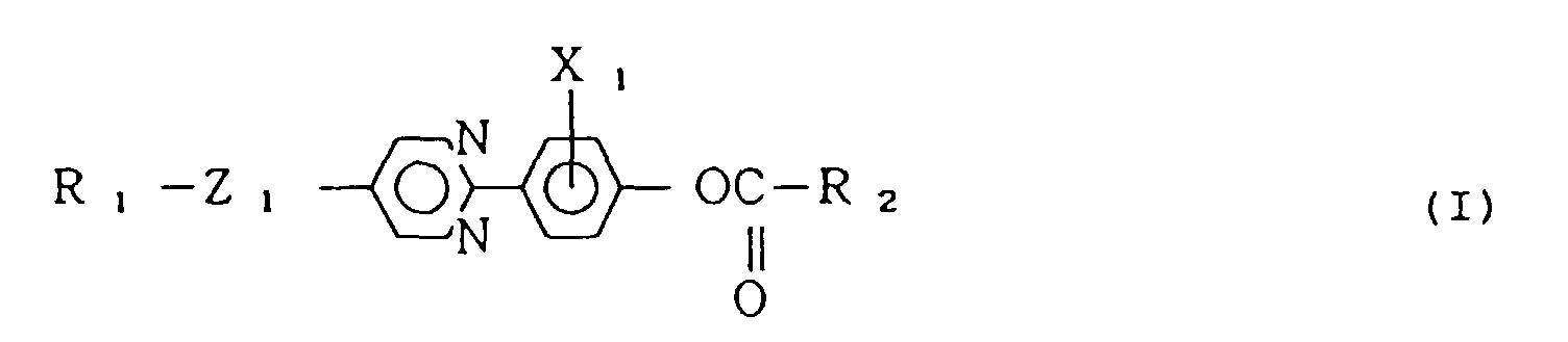


- Flüssigkristallzusammensetzung nach Anspruch 1, worin die nicht optisch aktive Flüssigkristallverbindung mit der allgemeinen Formel (I) die folgende allgemeine Formel (Ia) besitzt:


- Flüssigkristallzusammensetzung nach Anspruch 2, worin Z1 eine Einfachbindung oder -O- und X1 Cl oder F ist.
- Flüssigkristallzusammensetzung nach Anspruch 1, worin R1 und R2 ausgewählt sind aus einer der folgenden Gruppen (I-i) bis (I-iii):(I-i) einer Alkylgruppe mit 1 bis 16 Kohlenstoffatomen(I-ii)
 (I-iii)
- Flüssigkristallzusammensetzung nach Anspruch 1, worin die Zusammensetzung eine Verbindung umfaßt, die durch eine der folgenden Formeln (IV) bis (VIII) darstellt ist:


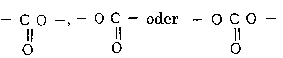


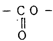

- Flüssigkristallzusammensetzung nach Anspruch 5, worin ein Zusammensetzungsverhältnis der Flüssigkristallverbindung mit der allgemeinen Formel (I) zu der Verbindung, die durch eine der Formeln (IV) bis (VIII) dargestellt ist, 1 bis 300 Gewichtsteile beträgt im Bezug auf 100 Gewichtsteile der Verbindung, die durch eine der Formeln (IV) bis (VIII) dargestellt ist.
- Flüssigkristallzusammensetzung nach Anspruch 5, worin, wenn die Zusammensetzung zwei oder mehr Flüssigkristallverbindungen mit der allgemeinen Formel (I) umfaßt, ein Zusammensetzungsverhältnis dieser zwei oder mehr Flüssigkristallverbindungen mit der allgemeinen Formel (I) zu der Verbindung, die durch eine der Formeln (IV) bis (VIII) dargestellt ist, 1 bis 500 Gewichtsteile beträgt im Bezug auf 100 Gewichtsteile der Verbindung, die durch eine der Formeln (IV) bis (VIII) dargestellt ist.
- Flüssigkristallvorrichtung, umfassend ein Paar Elektrodenträger, zwischen denen eine Flüssigkristallzusammensetzung gemäß einem der Ansprüche 1 bis 7 eingebracht ist.
- Flüssigkristallvorrichtung nach Anspruch 8, die weiter einen Ausrichtungsfilm umfaßt.
- Anzeigevorrichtung, die die Flüssigkristallvorrichtung nach Anspruch 8 umfaßt.
- Flüssigkristallzusammensetzung nach Anspruch 1 mit der chiralen, smektischen Phase, wobei die Flüssigkristallzusammensetzung eine Mischung umfaßt von:wenigstens einer nicht optisch aktiven Flüssigkristallverbindung mit der folgenden allgemeinen Formel (I):


 wenigstens eine Flüssigkristallverbindung mit der folgenden allgemeinen Formel (II):


- Flüssigkristallzusammensetzung nach Anspruch 11, worin die nicht optisch aktive Flüssigkristallverbindung mit der allgemeinen Formel (I) die folgende allgemeine Formel (Ia) aufweist:


- Flüssigkristallzusammensetzung nach Anspruch 12, worin Z2 und Z3 in den Formeln (II-a) bis (II-e) ausgewählt sind aus folgenden Elementen (II-i) bis (II-viii):(II-i) Z2 ist eine Einfachbindung und Z3 ist eine Einfachbindung,(II-ii) Z2 ist eine Einfachbindung und Z3 ist -O-,(II-iii) Z2 ist eine Einfachbindung und Z3 ist
 (II-iv) Z2 ist eine Einfachbindung und Z3 ist
 (II-v) Z2 ist -O- und Z3 ist eine Einfachbindung,(II-vi) Z2 ist -O- und Z3 ist -O-,(II-Vii) Z2 ist -0- und Z3 ist
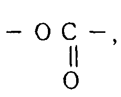 (II-viii) Z2 ist -O- und Z3 ist
- Flüssigkristallzusammensetzung nach Anspruch 12, worin R3 und R4 in den Formeln (II-a) bis (II-e) ausgewählt sind aus den Molekülteilen (II-ix)bis(II-xi):(II-ix) R3 und R4 sind jeweils eine n-Alkylgruppe mit 4 bis 14 Kohlenstoffatomen,(II-x) R3 ist eine n-Alkylgruppe mit 4 bis 14 Kohlenstoffatomen und R4 ist
 (II-xi) R3 ist eine n-Alkylgruppe mit 4 bis 14 Kohlenstoffatomen und R4 ist
- Flüssigkristallzusammensetzung nach Anspruch 10, worin die Zusammensetzung eine Verbindung umfaßt, die durch eine der Formeln (IV) bis (VIII) dargestellt ist.
- Flüssigkristallzusammensetzung nach Anspruch 15, worin ein Zusammensetzungsverhältnis der Flüssigkristallverbindung mit der allgemeinen Formel (I) und der Flüssigkristallverbindung mit der allgemeinen Formel (II) zu der Verbindung, die durch eine der Formeln (IV) bis (VIII) dargestellt ist, 1 bis 300 Gewichtsteile beträgt im Bezug auf 100 Gewichtsteile der Verbindung, die durch eine der Formeln (IV) bis (VIII) dargestellt ist.
- Flüssigkristallzusammensetzung nach Anspruch 15, worin, wenn die Zusammensetzung zwei oder mehr Flüssigkristallverbindungen umfaßt, von denen wenigstens eine der Flüssigkristallverbindungen durch die allgemeinen Formeln (I) oder (II) dargestellt ist, ein Zusammensetzungsverhältnis dieser Mischung der Flüssigkristallverbindungen mit den allgemeinen Formeln (I) oder (II) zu der Verbindung, die durch eine der Formeln (IV) bis (VIII) dargestellt ist, 1 bis 500 Gewichtsteile beträgt im Bezug auf 100 Gewichtsteile der Verbindung, die durch eine der Formeln (IV) bis (VIII) dargestellt ist.
- Flüssigkristallvorrichtung, umfassend ein Paar Elektrodenträger, zwischen denen eine der Flüssigkristallzusammensetzungen nach Anspruch 10 bis Anspruch 17 eingebracht ist.
- Flüssigkristallvorrichtung nach Anspruch 18, die weiter einen Ausrichtungsfilm umfaßt.
- Anzeigevorrichtung, die die Flüssigkristallvorrichtung nach Anspruch 18 umfaßt.
- Flüssigkristallzusammensetzung nach Anspruch 11, die weiter wenigstens eine Flüssigkristallverbindung mit der folgenden allgemeinen Formel (III) umfaßt:


- Flüssigkristallzusammensetzung nach Anspruch 21, worin die nicht optisch aktive Flüssigkristallverbindung mit der allgemeinen Formel (I) die folgende allgemeine Formel (Ia) aufweist:


- Flüssigkristallzusammensetzung nach Anspruch 22, worin Z4 und Z5 in den Formeln (III-a) bis (III-f) ausgewählt sind aus einer der folgenden Kombinationen (III-i) bis (III-v):(III-i) Z4 ist eine Einfachbindung und Z5 ist -O-CH2-,(III-ii) Z4 ist eine Einfachbindung und Z5 ist -COO-CH2-,(III-iii) Z4 ist eine Einfachbindung und Z5 ist -OCO-,(III-iv) Z4 ist -O- und Z5 ist gleich -O-CH2-,(III-v) Z4 ist -O- und Z5 ist gleich -COOCH2-.
- Flüssigkristallzusammensetzung nach Anspruch 21, worin die Zusammensetzung eine Verbindung umfaßt, die durch eine der Formeln (IV) bis (VIII) dargestellt ist.
- Flüssigkristallzusammensetzung nach Anspruch 24, worin ein Zusammensetzungsverhältnis der Flüssigkristallverbindungen mit den allgemeinen Formeln (I), (II) und (III) zu der Verbindung, die durch eine der Formeln (IV) bis (VIII) dargestellt ist, 1 bis 300 Gewichtsteile beträgt im Bezug auf 100 Gewichtsteile der Verbindung, die durch eine der Formeln (IV) bis (VIII) dargestellt ist.
- Flüssigkristallzusammensetzung nach Anspruch 24, worin, wenn die Zusammensetzung zwei oder mehr Flüssigkristallverbindungen umfaßt, von denen wenigstens eine der Flüssigkristallverbindungen durch die allgemeinen Formeln (I), (II) oder (III) dargestellt ist, das Zusammensetzungsverhältnis dieser Mischung von Flüssigkristallverbindungen mit den allgemeinen Formeln (I), (II) oder (III) bis 500 Gewichtsteile beträgt im Bezug auf 100 Gewichtsteile der Verbindung, die durch eine der Formeln (IV) bis (VIII) dargestellt ist.
- Flüssigkristallvorrichtung, umfassend ein Paar Elektrodenträger, zwischen denen eine der Flüssigkristallzusammensetzungen nach einem der Ansprüche 21 bis 26 eingebracht ist.
- Flüssigkristallvorrichtung nach Anspruch 27, die weiter einen Ausrichtungsfilm umfaßt.
- Anzeigevorrichtung, die die Flüssigkristallvorrichtung nach Anspruch 27 umfaßt.
- Flüssigkristallzusammensetzung nach Anspruch 1, umfassend eine Mischung aus:wenigstens einer nicht optisch aktiven Flüssigkristallverbindung mit der folgenden allgemeinen Formel (I):


 wenigstens einer Flüssigkristallverbindung mit der folgenden allgemeinen Formel (III):


- Flüssigkristallzusammensetzung nach Anspruch 30, worin die nicht optisch aktive Flüssigkristallverbindung mit der allgemeinen Formel (I) die folgende allgemeine Formel (Ia) besitzt:


die Verbindung mit der vorstehend genannten allgemeinen Formel (III) ausgewählt ist aus beliebigen Verbindungen mit den folgenden Formeln (II-a) bis (III-f):
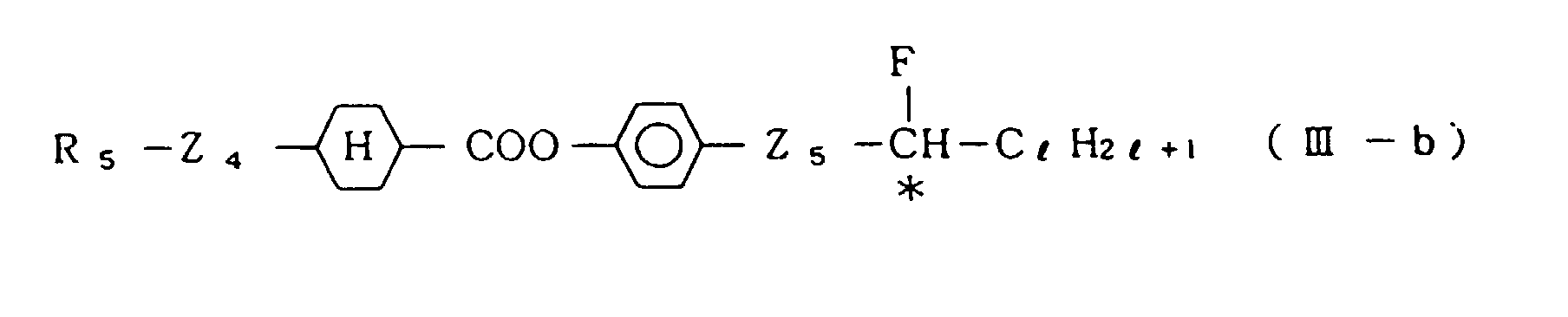


- Flüssigkristallzusammensetzung nach Anspruch 31, worin Z4 und Z5 in den Formeln (III-a) bis (III-f) ausgewählt sind aus einer der folgenden Kombinationen:(III-i) Z4 ist eine Einfachbindung und Z5 ist -O-CH2-,(III-ii) Z4 ist eine Einfachbindung und Z5 ist -COO-CH2-,(III-iii) Z4 ist eine Einfachbindung und Z5 ist -OCO-,(III-iv) Z4 ist -O- und Z5 ist gleich -O-CH2-,(III-v) Z4 ist -O- und Z5 ist gleich -COOCH2-.
- Flüssigkristallzusammensetzung nach Anspruch 30, worin die Zusammensetzung eine Verbindung umfaßt, die durch eine der folgenden Formeln (IV) bis (VIII) darstellt ist:



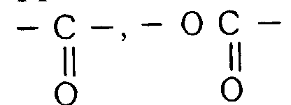


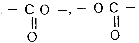


- Flüssigkristallzusammensetzung nach Anspruch 33, worin ein Zusammensetzungsverhältnis der Flüssigkristallverbindungen mit den allgemeinen Formeln (I) und (III) zu der Verbindung, die durch eine der Formeln (IV) bis (VIII) dargestellt ist, 1 bis 300 Gewichtsteile beträgt im Bezug auf 100 Gewichtsteile der Verbindung, die durch eine der Formeln (IV) bis (VIII) dargestellt ist.
- Flüssigkristallzusammensetzung nach Anspruch 33, worin, wenn die Zusammensetzung zwei oder mehr Flüssigkristallverbindungen mit den allgemeinen Formeln (I) und (III) umfaßt, das Zusammensetzungsverhältnis dieser Flüssigkristallverbindungen mit den allgemeinen Formeln (I) und (III) zu der Verbindung, die durch eine der Formeln (IV) bis (VIII) dargestellt ist, 1 bis 500 Gewichtsteile beträgt im Bezug auf 100 Gewichtsteile der Verbindung, die durch eine der Formeln (IV) bis (VIII) dargestellt ist.
- Flüssigkristallvorrichtung, umfassend ein Paar Elektrodenträger, zwischen denen eine Flüssigkristallzusammensetzung gemäß einem der Ansprüche 30 bis 35 eingebracht ist.
- Flüssigkristallvorrichtung nach Anspruch 36, die weiter einen Ausrichtungsfilm umfaßt.
- Anzeigevorrichtung, die die Flüssigkristallvorrichtung nach Anspruch 36 umfaßt.
Applications Claiming Priority (2)
| Application Number | Priority Date | Filing Date | Title |
|---|---|---|---|
| JP19883/90 | 1990-01-29 | ||
| JP2019883A JP2974353B2 (ja) | 1990-01-29 | 1990-01-29 | 強誘電性カイラルスメクチック液晶組成物およびこれを含む液晶素子 |
Publications (3)
| Publication Number | Publication Date |
|---|---|
| EP0440136A2 EP0440136A2 (de) | 1991-08-07 |
| EP0440136A3 EP0440136A3 (en) | 1992-03-18 |
| EP0440136B1 true EP0440136B1 (de) | 1997-04-02 |
Family
ID=12011607
Family Applications (1)
| Application Number | Title | Priority Date | Filing Date |
|---|---|---|---|
| EP91101076A Expired - Lifetime EP0440136B1 (de) | 1990-01-29 | 1991-01-28 | Flüssigkristallzusammensetzung und Vorrichtung die diese enthält |
Country Status (5)
| Country | Link |
|---|---|
| US (1) | US5391318A (de) |
| EP (1) | EP0440136B1 (de) |
| JP (1) | JP2974353B2 (de) |
| AT (1) | ATE151104T1 (de) |
| DE (1) | DE69125408T2 (de) |
Families Citing this family (6)
| Publication number | Priority date | Publication date | Assignee | Title |
|---|---|---|---|---|
| EP0352480B1 (de) * | 1988-06-24 | 1995-03-22 | Canon Kabushiki Kaisha | Ferroelektrische chirale smektische Flüssigkristallzusammensetzung und Vorrichtung mit dieser Zusammensetzung |
| DE4324630A1 (de) * | 1993-07-22 | 1995-01-26 | Hoechst Ag | Smektische Flüssigkristallmischung |
| JP3119342B2 (ja) * | 1995-01-31 | 2000-12-18 | キヤノン株式会社 | 液晶組成物、それを有する液晶素子及びそれらを有する液晶装置 |
| JP3119341B2 (ja) * | 1995-01-31 | 2000-12-18 | キヤノン株式会社 | 液晶組成物、それを有する液晶素子及びそれらを有する液晶装置 |
| US5858269A (en) * | 1995-09-20 | 1999-01-12 | Canon Kabushiki Kaisha | Liquid crystal device and liquid crystal apparatus |
| JP4198221B2 (ja) * | 1997-06-13 | 2008-12-17 | 株式会社半導体エネルギー研究所 | 光学活性化合物、反強誘電性液晶組成物、反強誘電性液晶組成物のしきい値を低減する方法及び光学活性化合物の製造方法 |
Family Cites Families (6)
| Publication number | Priority date | Publication date | Assignee | Title |
|---|---|---|---|---|
| DE3315295A1 (de) * | 1983-04-27 | 1984-10-31 | Merck Patent Gmbh, 6100 Darmstadt | Fluorhaltige pyrimidinderivate |
| CA1341038C (en) * | 1986-03-10 | 2000-06-27 | Masanao Kamei | Fluoroalkaned derivative |
| EP0267758A3 (de) * | 1986-11-10 | 1989-10-18 | Chisso Corporation | Alpha-substituierte Ester von Propionsäure |
| JPS63165344A (ja) * | 1986-12-26 | 1988-07-08 | Chisso Corp | 光学活性−2−メチルブチレ−ト類およびその利用物 |
| JPH0768518B2 (ja) * | 1987-07-08 | 1995-07-26 | チッソ株式会社 | 強誘電性液晶組成物 |
| ATE118029T1 (de) * | 1988-06-24 | 1995-02-15 | Canon Kk | Ferroelektrische chirale smektische flüssigkristallzusammensetzung und vorrichtung mit dieser zusammensetzung. |
-
1990
- 1990-01-29 JP JP2019883A patent/JP2974353B2/ja not_active Expired - Fee Related
-
1991
- 1991-01-25 US US07/645,720 patent/US5391318A/en not_active Expired - Fee Related
- 1991-01-28 AT AT91101076T patent/ATE151104T1/de not_active IP Right Cessation
- 1991-01-28 DE DE69125408T patent/DE69125408T2/de not_active Expired - Fee Related
- 1991-01-28 EP EP91101076A patent/EP0440136B1/de not_active Expired - Lifetime
Also Published As
| Publication number | Publication date |
|---|---|
| US5391318A (en) | 1995-02-21 |
| JP2974353B2 (ja) | 1999-11-10 |
| DE69125408D1 (de) | 1997-05-07 |
| DE69125408T2 (de) | 1997-10-23 |
| EP0440136A3 (en) | 1992-03-18 |
| ATE151104T1 (de) | 1997-04-15 |
| JPH03221589A (ja) | 1991-09-30 |
| EP0440136A2 (de) | 1991-08-07 |
Similar Documents
| Publication | Publication Date | Title |
|---|---|---|
| JP2941971B2 (ja) | 液晶組成物、それを有する液晶素子、それ等を用いた表示方法及び表示装置 | |
| JP2952141B2 (ja) | 液晶性化合物、それを含む液晶組成物、及びこれを用いた液晶素子 | |
| US5405553A (en) | Ferroelectric chiral smectic liquid crystal composition and liquid crystal device using same | |
| EP0440136B1 (de) | Flüssigkristallzusammensetzung und Vorrichtung die diese enthält | |
| US5173211A (en) | Ferroelectric chiral smectic liquid crystal composition and liquid crystal device using same | |
| EP0347942B1 (de) | Ferroelektrische chirale smektische Flüssigkristallzusammensetzung und Vorrichtung mit dieser Zusammensetzung | |
| US5413735A (en) | Liquid crystal composition, liquid crystal device using the liquid crystal composition, and display method and apparatus using the liquid crystal composition and device | |
| EP0555843B1 (de) | Mesomorphe Verbindung, flüssigkristalline Zusammensetzung, flüssigkristalline Vorrichtung, Display-Apparat und Display-Methode | |
| JPH09151179A (ja) | 光学活性化合物、これを含む液晶組成物、それを有する液晶素子、それらを用いた液晶装置及び表示方法 | |
| EP0666262B1 (de) | Optisch aktive Verbindung, Flüssigkristall das sie enthält, Flüssigkristallanzeigevorrichtung und Verfahren die sie verwendet | |
| JPH07309850A (ja) | 光学活性化合物、それを含有する液晶組成物、それを有する液晶素子及びそれらを用いた表示方法、表示装置 | |
| EP0351587B1 (de) | Ferroelektrische chirale smektische Flüssigkristallzusammensetzung und Vorrichtung mit dieser Zusammensetzung | |
| JP4272733B2 (ja) | 液晶組成物 | |
| EP0460624B1 (de) | Flüssigkristallzusammensetzung, Flüssigkristallvorrichtung, Anzeigevorrichtung und Anzeigemethode | |
| JP3171370B2 (ja) | 光学活性化合物、それを含有する液晶組成物、それを有する液晶素子及びそれらを用いた液晶装置及び表示方法 | |
| JP2796753B2 (ja) | カイラルスメクチック液晶組成物およびそれを使用した液晶素子 | |
| JPH08151578A (ja) | 光学活性化合物、それを含有する液晶組成物、それを有する液晶素子及びそれらを用いた表示方法、液晶装置 | |
| EP0355314B1 (de) | Ferroelektrische chirale smektische Flüssigkristallzusammensetzung und Vorrichtung mit dieser Zusammensetzung | |
| EP0458347B1 (de) | Flüssigkristallzusammensetzung und Anzeigevorrichtung, welche selbige verwendet | |
| JP2749822B2 (ja) | 液晶組成物およびこれを含む液晶素子 | |
| JP3213780B2 (ja) | 光学活性化合物、これを含有する液晶組成物、該液晶組成物を用いた液晶素子並びにこれらを用いた表示方法、表示装置 | |
| JPH0772442A (ja) | 光学活性化合物、それを含有する液晶組成物、それを有する液晶素子及びそれらを用いた表示方法、表示装置 | |
| JPH08109145A (ja) | エチニレン化合物、それを含有する液晶組成物、それを有する液晶素子及びそれらを用いた表示方法、表示装置 | |
| JPH08151577A (ja) | 光学活性化合物、それを含有する液晶組成物、それを有する液晶素子、それらを用いた液晶装置及び表示方法 | |
| JP3216752B2 (ja) | 光学活性化合物、それを含有する液晶組成物、それを有する液晶素子及びそれらを用いた表示方法、表示装置 |
Legal Events
| Date | Code | Title | Description |
|---|---|---|---|
| PUAI | Public reference made under article 153(3) epc to a published international application that has entered the european phase |
Free format text: ORIGINAL CODE: 0009012 |
|
| AK | Designated contracting states |
Kind code of ref document: A2 Designated state(s): AT BE CH DE DK ES FR GB GR IT LI LU NL SE |
|
| PUAL | Search report despatched |
Free format text: ORIGINAL CODE: 0009013 |
|
| AK | Designated contracting states |
Kind code of ref document: A3 Designated state(s): AT BE CH DE DK ES FR GB GR IT LI LU NL SE |
|
| 17P | Request for examination filed |
Effective date: 19920804 |
|
| 17Q | First examination report despatched |
Effective date: 19931210 |
|
| GRAG | Despatch of communication of intention to grant |
Free format text: ORIGINAL CODE: EPIDOS AGRA |
|
| GRAH | Despatch of communication of intention to grant a patent |
Free format text: ORIGINAL CODE: EPIDOS IGRA |
|
| GRAH | Despatch of communication of intention to grant a patent |
Free format text: ORIGINAL CODE: EPIDOS IGRA |
|
| GRAA | (expected) grant |
Free format text: ORIGINAL CODE: 0009210 |
|
| AK | Designated contracting states |
Kind code of ref document: B1 Designated state(s): AT BE CH DE DK ES FR GB GR IT LI LU NL SE |
|
| PG25 | Lapsed in a contracting state [announced via postgrant information from national office to epo] |
Ref country code: ES Free format text: THE PATENT HAS BEEN ANNULLED BY A DECISION OF A NATIONAL AUTHORITY Effective date: 19970402 Ref country code: IT Free format text: LAPSE BECAUSE OF FAILURE TO SUBMIT A TRANSLATION OF THE DESCRIPTION OR TO PAY THE FEE WITHIN THE PRE;WARNING: LAPSES OF ITALIAN PATENTS WITH EFFECTIVE DATE BEFORE 2007 MAY HAVE OCCURRED AT ANY TIME BEFORE 2007. THE CORRECT EFFECTIVE DATE MAY BE DIFFERENT FROM THE ONE RECORDED.SCRIBED TIME-LIMIT Effective date: 19970402 Ref country code: BE Effective date: 19970402 Ref country code: NL Effective date: 19970402 Ref country code: DK Effective date: 19970402 Ref country code: GR Free format text: LAPSE BECAUSE OF FAILURE TO SUBMIT A TRANSLATION OF THE DESCRIPTION OR TO PAY THE FEE WITHIN THE PRESCRIBED TIME-LIMIT Effective date: 19970402 Ref country code: LI Effective date: 19970402 Ref country code: AT Effective date: 19970402 Ref country code: CH Effective date: 19970402 |
|
| REF | Corresponds to: |
Ref document number: 151104 Country of ref document: AT Date of ref document: 19970415 Kind code of ref document: T |
|
| REG | Reference to a national code |
Ref country code: CH Ref legal event code: EP |
|
| REF | Corresponds to: |
Ref document number: 69125408 Country of ref document: DE Date of ref document: 19970507 |
|
| ET | Fr: translation filed | ||
| PG25 | Lapsed in a contracting state [announced via postgrant information from national office to epo] |
Ref country code: SE Effective date: 19970702 |
|
| NLV1 | Nl: lapsed or annulled due to failure to fulfill the requirements of art. 29p and 29m of the patents act | ||
| REG | Reference to a national code |
Ref country code: CH Ref legal event code: PL |
|
| PG25 | Lapsed in a contracting state [announced via postgrant information from national office to epo] |
Ref country code: LU Free format text: LAPSE BECAUSE OF NON-PAYMENT OF DUE FEES Effective date: 19980128 |
|
| PLBE | No opposition filed within time limit |
Free format text: ORIGINAL CODE: 0009261 |
|
| STAA | Information on the status of an ep patent application or granted ep patent |
Free format text: STATUS: NO OPPOSITION FILED WITHIN TIME LIMIT |
|
| 26N | No opposition filed | ||
| REG | Reference to a national code |
Ref country code: GB Ref legal event code: IF02 |
|
| PGFP | Annual fee paid to national office [announced via postgrant information from national office to epo] |
Ref country code: FR Payment date: 20030110 Year of fee payment: 13 |
|
| PGFP | Annual fee paid to national office [announced via postgrant information from national office to epo] |
Ref country code: GB Payment date: 20030122 Year of fee payment: 13 |
|
| PGFP | Annual fee paid to national office [announced via postgrant information from national office to epo] |
Ref country code: DE Payment date: 20030206 Year of fee payment: 13 |
|
| PG25 | Lapsed in a contracting state [announced via postgrant information from national office to epo] |
Ref country code: GB Free format text: LAPSE BECAUSE OF NON-PAYMENT OF DUE FEES Effective date: 20040128 |
|
| PG25 | Lapsed in a contracting state [announced via postgrant information from national office to epo] |
Ref country code: DE Free format text: LAPSE BECAUSE OF NON-PAYMENT OF DUE FEES Effective date: 20040803 |
|
| GBPC | Gb: european patent ceased through non-payment of renewal fee |
Effective date: 20040128 |
|
| PG25 | Lapsed in a contracting state [announced via postgrant information from national office to epo] |
Ref country code: FR Free format text: LAPSE BECAUSE OF NON-PAYMENT OF DUE FEES Effective date: 20040930 |
|
| REG | Reference to a national code |
Ref country code: FR Ref legal event code: ST |