EP0440184A1 - Copper alloy wire, and insulated electric wires and multiple core parallel bonded wires made of the same - Google Patents
Copper alloy wire, and insulated electric wires and multiple core parallel bonded wires made of the same Download PDFInfo
- Publication number
- EP0440184A1 EP0440184A1 EP91101193A EP91101193A EP0440184A1 EP 0440184 A1 EP0440184 A1 EP 0440184A1 EP 91101193 A EP91101193 A EP 91101193A EP 91101193 A EP91101193 A EP 91101193A EP 0440184 A1 EP0440184 A1 EP 0440184A1
- Authority
- EP
- European Patent Office
- Prior art keywords
- wire
- copper alloy
- alloy wire
- insulated electric
- wires
- Prior art date
- Legal status (The legal status is an assumption and is not a legal conclusion. Google has not performed a legal analysis and makes no representation as to the accuracy of the status listed.)
- Granted
Links
- 229910000881 Cu alloy Inorganic materials 0.000 title claims abstract description 61
- 238000000137 annealing Methods 0.000 claims abstract description 46
- 239000010949 copper Substances 0.000 claims abstract description 31
- 238000009413 insulation Methods 0.000 claims abstract description 30
- 239000004020 conductor Substances 0.000 claims abstract description 24
- 238000010438 heat treatment Methods 0.000 claims abstract description 20
- 239000000203 mixture Substances 0.000 claims abstract description 16
- 239000012535 impurity Substances 0.000 claims abstract description 11
- 239000010410 layer Substances 0.000 claims description 33
- RYGMFSIKBFXOCR-UHFFFAOYSA-N Copper Chemical compound [Cu] RYGMFSIKBFXOCR-UHFFFAOYSA-N 0.000 claims description 24
- 229910052802 copper Inorganic materials 0.000 claims description 23
- QVGXLLKOCUKJST-UHFFFAOYSA-N atomic oxygen Chemical compound [O] QVGXLLKOCUKJST-UHFFFAOYSA-N 0.000 claims description 14
- 229910052760 oxygen Inorganic materials 0.000 claims description 14
- 239000001301 oxygen Substances 0.000 claims description 14
- 239000004814 polyurethane Substances 0.000 claims description 9
- 229920002635 polyurethane Polymers 0.000 claims description 9
- 239000011241 protective layer Substances 0.000 claims description 8
- 239000012790 adhesive layer Substances 0.000 claims description 5
- 238000004804 winding Methods 0.000 description 17
- 239000011248 coating agent Substances 0.000 description 13
- 238000000576 coating method Methods 0.000 description 13
- 230000000052 comparative effect Effects 0.000 description 12
- 238000000034 method Methods 0.000 description 12
- 238000012546 transfer Methods 0.000 description 12
- 238000005452 bending Methods 0.000 description 11
- 239000011261 inert gas Substances 0.000 description 9
- 239000000463 material Substances 0.000 description 9
- -1 polyhydantoin Polymers 0.000 description 9
- 238000012360 testing method Methods 0.000 description 9
- 239000004952 Polyamide Substances 0.000 description 7
- BQCADISMDOOEFD-UHFFFAOYSA-N Silver Chemical compound [Ag] BQCADISMDOOEFD-UHFFFAOYSA-N 0.000 description 7
- 229920002037 poly(vinyl butyral) polymer Polymers 0.000 description 7
- 229920002647 polyamide Polymers 0.000 description 7
- 229910052709 silver Inorganic materials 0.000 description 7
- 239000004332 silver Substances 0.000 description 7
- 239000004840 adhesive resin Substances 0.000 description 5
- 229920006223 adhesive resin Polymers 0.000 description 5
- 210000003298 dental enamel Anatomy 0.000 description 5
- 239000003822 epoxy resin Substances 0.000 description 5
- LNEPOXFFQSENCJ-UHFFFAOYSA-N haloperidol Chemical compound C1CC(O)(C=2C=CC(Cl)=CC=2)CCN1CCCC(=O)C1=CC=C(F)C=C1 LNEPOXFFQSENCJ-UHFFFAOYSA-N 0.000 description 5
- 229920000647 polyepoxide Polymers 0.000 description 5
- 239000004962 Polyamide-imide Substances 0.000 description 4
- 239000004642 Polyimide Substances 0.000 description 4
- 229920003055 poly(ester-imide) Polymers 0.000 description 4
- 229920002312 polyamide-imide Polymers 0.000 description 4
- 229920000728 polyester Polymers 0.000 description 4
- 229920001721 polyimide Polymers 0.000 description 4
- 229920002050 silicone resin Polymers 0.000 description 4
- 238000007796 conventional method Methods 0.000 description 3
- 230000003247 decreasing effect Effects 0.000 description 3
- 230000014759 maintenance of location Effects 0.000 description 3
- 238000001953 recrystallisation Methods 0.000 description 3
- 229910000859 α-Fe Inorganic materials 0.000 description 3
- RTZKZFJDLAIYFH-UHFFFAOYSA-N Diethyl ether Chemical compound CCOCC RTZKZFJDLAIYFH-UHFFFAOYSA-N 0.000 description 2
- 230000007423 decrease Effects 0.000 description 2
- 238000004534 enameling Methods 0.000 description 2
- 239000013034 phenoxy resin Substances 0.000 description 2
- 229920006287 phenoxy resin Polymers 0.000 description 2
- 229920002492 poly(sulfone) Polymers 0.000 description 2
- 229920005989 resin Polymers 0.000 description 2
- 239000011347 resin Substances 0.000 description 2
- 229910000679 solder Inorganic materials 0.000 description 2
- 239000007858 starting material Substances 0.000 description 2
- 239000004677 Nylon Substances 0.000 description 1
- 150000008065 acid anhydrides Chemical class 0.000 description 1
- 230000004913 activation Effects 0.000 description 1
- 229920003180 amino resin Polymers 0.000 description 1
- 230000005540 biological transmission Effects 0.000 description 1
- 238000005266 casting Methods 0.000 description 1
- 230000015556 catabolic process Effects 0.000 description 1
- 239000003795 chemical substances by application Substances 0.000 description 1
- 150000001875 compounds Chemical class 0.000 description 1
- 239000000356 contaminant Substances 0.000 description 1
- 230000002542 deteriorative effect Effects 0.000 description 1
- 238000011161 development Methods 0.000 description 1
- 238000011835 investigation Methods 0.000 description 1
- 239000012948 isocyanate Substances 0.000 description 1
- 238000004519 manufacturing process Methods 0.000 description 1
- 239000002184 metal Substances 0.000 description 1
- 229910052751 metal Inorganic materials 0.000 description 1
- 229910052755 nonmetal Inorganic materials 0.000 description 1
- 229920001778 nylon Polymers 0.000 description 1
- 230000001590 oxidative effect Effects 0.000 description 1
- 239000011527 polyurethane coating Substances 0.000 description 1
- 239000011342 resin composition Substances 0.000 description 1
- 238000000926 separation method Methods 0.000 description 1
- 230000008054 signal transmission Effects 0.000 description 1
- 229920001187 thermosetting polymer Polymers 0.000 description 1
Images
Classifications
-
- H—ELECTRICITY
- H01—ELECTRIC ELEMENTS
- H01B—CABLES; CONDUCTORS; INSULATORS; SELECTION OF MATERIALS FOR THEIR CONDUCTIVE, INSULATING OR DIELECTRIC PROPERTIES
- H01B5/00—Non-insulated conductors or conductive bodies characterised by their form
- H01B5/02—Single bars, rods, wires, or strips
- H01B5/04—Single bars, rods, wires, or strips wound or coiled
-
- C—CHEMISTRY; METALLURGY
- C22—METALLURGY; FERROUS OR NON-FERROUS ALLOYS; TREATMENT OF ALLOYS OR NON-FERROUS METALS
- C22F—CHANGING THE PHYSICAL STRUCTURE OF NON-FERROUS METALS AND NON-FERROUS ALLOYS
- C22F1/00—Changing the physical structure of non-ferrous metals or alloys by heat treatment or by hot or cold working
- C22F1/08—Changing the physical structure of non-ferrous metals or alloys by heat treatment or by hot or cold working of copper or alloys based thereon
-
- H—ELECTRICITY
- H01—ELECTRIC ELEMENTS
- H01B—CABLES; CONDUCTORS; INSULATORS; SELECTION OF MATERIALS FOR THEIR CONDUCTIVE, INSULATING OR DIELECTRIC PROPERTIES
- H01B1/00—Conductors or conductive bodies characterised by the conductive materials; Selection of materials as conductors
- H01B1/02—Conductors or conductive bodies characterised by the conductive materials; Selection of materials as conductors mainly consisting of metals or alloys
- H01B1/026—Alloys based on copper
-
- Y—GENERAL TAGGING OF NEW TECHNOLOGICAL DEVELOPMENTS; GENERAL TAGGING OF CROSS-SECTIONAL TECHNOLOGIES SPANNING OVER SEVERAL SECTIONS OF THE IPC; TECHNICAL SUBJECTS COVERED BY FORMER USPC CROSS-REFERENCE ART COLLECTIONS [XRACs] AND DIGESTS
- Y10—TECHNICAL SUBJECTS COVERED BY FORMER USPC
- Y10T—TECHNICAL SUBJECTS COVERED BY FORMER US CLASSIFICATION
- Y10T428/00—Stock material or miscellaneous articles
- Y10T428/12—All metal or with adjacent metals
- Y10T428/12431—Foil or filament smaller than 6 mils
Definitions
- the present invention relates to a copper alloy wire suitable for a conductor for use in wirings for magnetic heads, and insulated electric wires and multiple core parallel bonded wires including the copper alloy wire as a conductor. More particularly, the present invention relates to those which are suitable for use as fine wires having excellent electroconductivity, tensile strength and elongation and having a wire diameter of no larger than 90 ⁇ m
- Another object of the present invention is to provide insulated electric wires made from such improved copper alloy wire.
- Still another object of the present invention is to provide multiple core parallel bonded wires made from such improved copper alloy wire.
- the present invention has been completed and provides a copper alloy wire having a composition composed of no less than 0.01 % by weight of Ag and balance Cu and unavoidable impurities, wherein said copper alloy wire has been prepared by drawing a wire stock having said composition at a reduction ratio of no lower than 40 % and subjecting said wire stock to heat treatment for half annealing to have a tensile strength of no lower than 27 kg ⁇ f/mm2 and an elongation of 5 %.
- the present invention provides an insulated electric wire comprising the above copper alloy wire as a conductor and an insulation layer covering the conductor.
- the present invention provides a multiple core parallel bonded wire comprising two or more of the above insulated electric wire parallel bonded to each other as cores.
- the copper alloy wire of the present invention is made of a copper alloy which comprises 0.01 % by weight of Ag and balance Cu and unavoidable impurities.
- the content of Ag is preferably in the range of 0.02 to 0.5 % by weight.
- the Cu may be tough pitch copper which is usually used but it is preferred to use oxygen free copper (OFC), if possible.
- OFC oxygen free copper
- the oxygen free copper is preferably of a purity of no lower than 99.99%.
- the Ag content in the wire stock is set up to no less than 0.01 % by weight.
- the Ag content exceeding 0.5 % by weight is inconvenient because not only the resistance of the conductor increases but also cost becomes higher.
- the oxygen content of the oxygen free copper is set up to no more than 30 ppm. If it exceeds 30 ppm, the amount of non-metal contaminants composed of oxides increases, resulting in that there tends to occur breakage of the wire upon drawing.
- the oxygen free copper to be used in the present invention may contain some unavoidable impurities but it is preferred that total amount of the unavoidable impurities be no more than 0.009 % by weight.
- Wires are cast from the copper alloy having the above-described composition by a conventional casting method, and then the resulting wires are processed by a conventional drawing method at a reduction ratio of no lower than 40 % to obtain multiple fine wires having a desired outer diameter, e.g., 50 ⁇ m.
- the drawing can be carried out dividedly in several steps. For example, wires having a diameter of 16 to 20 mm are cast and drawn to wires having a diameter of 1 to 2 mm.
- the wires are annealed in an inert gas atmosphere to full anneal them (full softening treatment), followed by drawing them at a reduction ratio of no lower than 40 %, preferably no lower than 90 %, and more preferably no lower than 99.9 %, to obtain fine wires having an objective outer diameter, for example, 50 ⁇ m.
- reduction ratio of no lower than 40 % referred to herein is meant that the reduction ratio of the wire after the final drawing step in order to obtain the objective outer diameter of the wire is no lower than 40 %. Therefore, while it is possible to carry out annealing properly in a series of drawing steps, the reduction ratio of the wire in the final drawing must be no lower than 40 %.
- the resulting copper alloy wire cannot have a desired tensile strength after production.
- heat treatment for half annealing herein is meant a heat treatment which is carried out on a generally cold-worked metal to a degree such that recrystallization proceeds halfway.
- specific conditions under which the heat treatment for half annealing is carried out include temperature and time which can be set up in very wide ranges, respectively. Principally, it is sufficient to select temperature and time conditions which meet activation energy for recrystallization.
- the conditions, i.e., temperature and time of heat treatment for half annealing are set up so that the wire after the heat treatment for half annealing has a tensile strength of no lower than 27 kg ⁇ f/mm2, preferably 27 to 35 f/mm2 and an elongation of no lower than 5 %, preferably 5 to 15 %. It is preferred to carry out the heat treatment for half annealing in a non-oxidative atmosphere such as an inert gas atmosphere.
- the copper alloy wire has a tensile strength of lower than 27 kg ⁇ f/mm2, a desired bending strength cannot be obtained in the winding step and breakage of the wire tends to occur.
- the wire has an elongation of lower than 5 %, the wound, coil-shaped wire tends to be bent back to cause so-called spring back, thus making it difficult to carry out winding. Therefore, it is necessary to carry out heat treatment for half annealing so that there can be obtained sufficient mechanical characteristics such as a tensile strength of no lower than 27 kg ⁇ f/mm2 and an elongation of no lower than 5 %.
- fine wires having a diameter of no larger than 90 ⁇ m, preferably no larger than 50 ⁇ m from the thus-obtained wire.
- the copper alloy wire thus obtained has a tensile strength more than is necessary and a proper elongation, and its mechanical characteristics such as tensile strength and elongation in the subsequent enameling step are not deteriorated to below values desired for cores of winding.
- the wire causes no breakage in the step of winding and has an excellent bending resistance, resulting in that the terminals of the copper alloy wire are not bent, for example, when it is passed through the window portion of a magnetic head in the step of winding it around the ferrite core portion of the magnetic head.
- the mechanical characteristics, such as bending resistance, tensile strength and elongation, of the wire can be improved without deteriorating its electroconductivity so that breakage and bending of the copper alloy wire in the step of winding can be prevented.
- the insulated electric wire of the invention comprises the above-described copper alloy wire as a conductor and an insulation layer covered on the conductor.
- the insulation layer can be formed by coating and baking an insulation coating material such as polyester, polyurethane, polyesterimide, polyamideimide, polyamide, polyhydantoin, polyimide, polyvinylformal, polyvinylbutyral, epoxy resins and silicone resins by conventional methods.
- an insulation coating material such as polyester, polyurethane, polyesterimide, polyamideimide, polyamide, polyhydantoin, polyimide, polyvinylformal, polyvinylbutyral, epoxy resins and silicone resins by conventional methods.
- the coating materials most preferred is polyurethane in view of solderability.
- the thickness of the insulation layer is not limited particularly but is preferably small for the purpose of the present invention. Usually, the thickness of the insulation layer is no larger than 10 ⁇ m, preferably 5 ⁇ m.
- a protective layer may be provided on the insulation layer, if desired.
- the protective layer which is provided in order to prevent mechanical damages and the like of the insulation layer, can be formed by coating and baking an insulation coating material such as polyester, polyurethane, polyesterimide, polyamideimide, polyamide, polyhydantoin, polyimide, polyvinylformal, polyvinylbutyral, epoxy resins and silicone resins.
- an insulation coating material such as polyester, polyurethane, polyesterimide, polyamideimide, polyamide, polyhydantoin, polyimide, polyvinylformal, polyvinylbutyral, epoxy resins and silicone resins.
- a self-lubricating layer made of polyamide or the like or a self-bonding layer made of polyvinylbutyral, polyamide or the like may be provided on the insulation layer.
- the insulated electric wire of the present invention be an fine electric wire also having a small outer diameter of no larger than 90 ⁇ m.
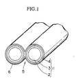
- Fig. 1 illustrates a multiple core parallel bonded wire according to one embodiment of the present invention.
- reference numeral 1 designates an insulated wire.
- the insulated wire 1 includes a conductor 2 on which an insulation layer 3 is covered, and a protective layer 4 is further covered on the insulation layer 3.
- the conductor 2 is made of the above-described copper alloy wire, whose diameter is not limited particularly. However, for the purpose of the present invention, it is desirable that the diameter is no larger than 50 ⁇ m as described above, preferably no larger than 40 ⁇ m.
- the insulation layer can be formed by coating and baking an insulation coating material such as polyester, polyurethane, polyesterimide, polyamideimide, polyamide, polyhydantoin, polyimide, polyvinylformal, polyvinylbutyral, epoxy resins and silicone resins by conventional methods. Among these coating materials, most preferred is polyurethane in view of solderability.
- the thickness of the insulation layer 3 is not limited particularly but is preferably small for the purpose of the present invention. Usually, the thickness of the insulation layer 3 is no larger than 10 ⁇ m, preferably 5 ⁇ m.
- a protective layer 4 to form the insulated wire 1.
- the protection layer 4 is to prevent mechanical damages or the like of the insulation layer 3 and thus is not always indispensable.
- the protection layer 4 can be formed by coating and baking an insulation coating material such as polyester, polyurethane, polyesterimide, polyamideimide, polyamide, polyhydantoin, polyimide, polyvinylformal, polyvinylbutyral, epoxy resins and silicone resins by conventional methods. Among these coating materials, most preferred is polyurethane in view of solderability.
- a self-lubricating layer made of nylon or the like or a self-bonding layer made of polyvinylbutyral or the like may be provided on the insulation layer 3.
- reference numeral 6 designates an adhesive layer 6 composed of the adhesive resin composition.
- the adhesive resin composition there can be cited, for example, polyamide, polyvinylbutyral, polysulfone, polysulfone ether, epoxy resins, phenoxy resins and the like, and thermosetting resins composed of one or more of the above-described resins and a curing agent such as an isocyanate compound, an aminoplast compound or an acid anhydride.
- the thickness of the adhesive layer 6 is on the order of 1 to 10 ⁇ m. Of course, the thinner the more preferred.
- Double core parallel bonded wire 5 can also be obtained without using the above-described adhesive resin composition. That is, the protective layer 4 or the insulation layer 3 itself can be used simultaneously as an adhesive resin composition. This can be realized by properly selecting the resin composition which constitutes the protective layer 4 or the insulation layer 3 and properly setting up the thickness thereof.
- the parallel bonded wire may be those which can be obtained by bonding two pieces of the insulated wire 1 to each other along their longitudinal direction with interruptions or intermittently.
- bonded portions and non-bonded portions may appear alternately in the longitudinal direction of the double core parallel bonded wire.
- three or more pieces of the insulated wire 1 can be arranged parallel to each other and bonded to form a multiple core parallel bonded wire.
- the multiple core parallel bonded wire thus obtained has a high tensile strength despite its conductor diameter being small and therefore it will not break upon automatic winding or upon assembling after separation of the wire stock.
- the resistance of the conductor does not increase, resulting in that there is no increase in the direct current resistance even when the number of winding increases.
- the use of oxygen free copper gives rise to good high frequency characteristics, permitting transmission of signals up to 10 MHz at a low transmission loss.
- Silver (Ag) was added to oxygen free copper containing 8 ppm of oxygen and 0.006 % by weight of unavoidable impurities in various proportions and the resulting copper alloys were manufactured by a dip forming method to obtain wires having an outer diameter of 16 mm. Then the wires were drawn at a reduction ratio of no lower than 99.9 % to obtain fine wires of a diameter of 40 ⁇ m using a continuous drawing machine. The fine wires were subjected to heat treatment for half annealing in an annealing furnace at 400°C to obtain conductors.
- Silver (0.1 % by weight) was added to oxygen free copper containing 8 ppm of oxygen and 0.006 % by weight of unavoidable impurities, and the resulting copper alloy was drawn by a dip forming method to obtain a wire having a diameter of 2.6 mm. Then the wire was drawn to obtain a wire having a diameter of 50 to 1270 ⁇ m, which was then fully annealed in an annealing furnace at 600°C.
- the resulting wire was drawn at various reduction ratios to obtain fine wires having a diameter of 40 ⁇ m.
- Silver (0.1 % by weight) was added to oxygen free copper containing 8 ppm of oxygen and 0.006 % by weight of unavoidable impurities, and the resulting copper alloy was drawn by a dip forming method to obtain a wire having a diameter of 16 mm. Then the wire was drawn to obtain a wire having a diameter of 1.27 mm, which was full annealed. Then the wire was drawn at a reduction ratio of no lower than 99.9 % to obtain an fine wire having a diameter of 40 ⁇ m.
- the fine wire was subjected to no heat treatment for half annealing (Test Example 10), subjected to heat treatment for half annealing at a temperature of 600°C (Test Example 11) or subjected to heart treatment for half annealing at a temperature of 700°C (Test Example 12) to prepare respective conductors.
- the fine insulated wire was measured on the number of pin-holes in the insulation layer, dielectric breakdown voltage, tensile strength, elongation and solderability.
- the number of pin-holes was expressed in number per 5 m of enameled wire according to JIS-C-3003K.
- the solderability was judged to be good when the wire was wetted with solder at a solder temperature of 380°C in 2 seconds.
- a phenoxy resin coating material was coated on the fine insulated electric wire obtained in Test Example 13 (outer diameter: 38 ⁇ m) and baked to cover thereon an adhesive layer having a thickness of 1 ⁇ m. Two pieces of the thus obtained wire were arranged parallel to each other and passed through a heating furnace at about 200°C in close contact with each other to melt the adhesive layer to bond the wires, thus preparing an fine double core parallel bonded wire.
- the graph illustrated in Fig. 2 represents relationship between the wire diameter and tensile strength for each of an enameled wire (A) containing 0.1 % by weight of silver, an enameled wire (B) containing no silver, a double core parallel bonded wire (C) obtained from the enameled wire (A) and a double core parallel bonded wire (D) obtained from the enameled wire (B).
- the graph clearly shows that the tensile strength of the wire was significantly improved by the addition of silver.
- a copper alloy wire containing 0.01 % by weight of Ag and having a diameter of 16 mm was drawn to obtain a wire stock having a diameter of 2.6 mm. Then, after fully annealing it in a furnace of an inert gas atmosphere, the stock wire was drawn at a reduction ratio of no lower than 99.9 % to obtain an fine wire having a diameter of 40 ⁇ m. Thereafter, the fine wire was converted in a half-softened state by annealing it at a temperature of 400°C in a transfer annealing furnace of an inert gas atmosphere to prepare an Ag containing-copper alloy fine wire having a tensile strength of 35 kg ⁇ f/mm2 and an elongation of 5 %.
- Example 2 The procedures of Example 2 were repeated except that the speed at which the wire was transferred was made slower to make longer retention time in the transfer annealing furnace, i.e., annealing time than that in Example 2 to prepare an Ag containing-copper alloy fine wire having a tensile strength of 27 kg ⁇ f/mm2 and an elongation of 14.5 %.
- a copper alloy wire containing 0.1 % by weight of Ag and having a diameter of 16 mm was drawn to obtain a wire stock having a diameter of 2.6 mm. Then, after fully annealing it in a furnace of an inert gas atmosphere, the stock wire was drawn to obtain an fine wire having a diameter of 52 ⁇ m. Further, after fully annealing it in a transfer annealing furnace of an inert gas atmosphere, the wire stock thus obtained was drawn at a reduction ratio of 40.8 % to obtain an fine wire having a diameter of 40 ⁇ m.
- the fine wire was converted in a half-softened state by annealing it at a temperature of 400°C in a transfer annealing furnace of an inert gas atmosphere to prepare an Ag containing-copper alloy fine wire having a tensile strength of 27.7 kg ⁇ f/mm2 and an elongation of 11
- Example 2 The procedures of Example 2 were repeated except that the speed at which the wire was transferred was made slower to make longer retention time in the transfer annealing furnace, i.e., annealing time than that in Example 3 to prepare an Ag containing-copper alloy fine wire having a tensile strength of 23.2 kg ⁇ f/mm2 and an elongation of 16.5 %.
- Example 2 The procedures of Example 2 were repeated except that the temperature of the transfer annealing furnace was changed to 300°C and the speed at which the wire was transferred was made slower to make longer retention time in the transfer annealing furnace, i.e., annealing time than that in Example 2 to prepare an Ag containing-copper alloy fine wire having a tensile strength of 41 kg ⁇ f/mm2 and an elongation of 2.5 %.
- Example 2 The procedures of Example 2 were repeated using the same annealing treatment and reduction ratio except that the starting material was changed to 99.99 % by weight (four nine) oxygen free copper wire (diameter: 16 mm) and the temperature of the transfer annealing furnace was changed to 300°C to prepare a pure copper fine wire having a tensile strength of 28 kg ⁇ f/mm2 and an elongation of 10 %.
- Example 2 The procedures of Example 2 were repeated using the same full annealing treatment and reduction ratio except that the starting material was changed to 0.005 % by weight Ag containing-copper alloy rod (diameter: 16 mm) and the temperature of the transfer annealing furnace was changed to 300°C to prepare an Ag containing-copper alloy fine wire having a tensile strength of 32 kg ⁇ f/mm2 and an elongation of 7 %.
- Example 4 The same copper alloy wire as used in Example 4 was drawn to obtain a wire stock having a diameter of 2.6 mm. Then, after fully annealing it in a furnace of an inert gas atmosphere, the stock wire was drawn to obtain a wire having a diameter of 43 ⁇ m. Further, after fully annealing it in a transfer annealing furnace of an inert gas atmosphere, the wire thus obtained was drawn at a reduction ratio of 13.5 % to obtain an Ag containing-copper alloy fine wire having a diameter of 40 ⁇ m and having mechanical characteristics of a tensile strength of 25 kg.f/mm2 and an elongation of 18 %.
- the copper alloy fine wires (including copper fine wires) obtained in Examples 2 to 4 and Comparative Examples 1 to 5 were measured on their conductivity (% IACS). Then, after coating enamel on the periphery of the copper or copper alloy wire wires and baking, they were examined if they were softened. Furthermore, each of the resulting wire wires was wound around the ferrite core portion of a magnetic head and degree of easiness of winding was examined. The results obtained are shown in Table 6 below.
- the copper alloy or pure-copper fine wires obtained in Comparative Examples 1 to 5 had sufficiently high conductivities of 99 to 101 % IACS.
- the copper alloy fine wire obtained in Comparative Example 1 in which the transfer annealing time was longer than Example 1 and that obtained in Comparative Example 5 in which the reduction ratio was as low as 13.5 % did not show softening after the baking enamel but had insufficient tensile strengths in the winding step, resulting in that they had poor bending resistances and thus were difficult to be wound.
- the copper alloy fine wire obtained in Comparative Example 2 in which the transfer annealing time was shorter than Example 2 did not show softening after the baking enamel but caused spring-back because of insufficient elongation during he winding step, thus making it difficult to wind it.
- the pure copper fine wire containing no Ag obtained in Comparative Example 3 and the copper alloy fine wire with an Ag content of 0.005 % by weight obtained in Comparative Example 4 suffered from softening due to the baking of enamel to decrease their tensile strengths, resulting in that their bending resistances were poor and therefore it was difficult to wind them.
Landscapes
- Chemical & Material Sciences (AREA)
- Physics & Mathematics (AREA)
- Thermal Sciences (AREA)
- Crystallography & Structural Chemistry (AREA)
- Engineering & Computer Science (AREA)
- Materials Engineering (AREA)
- Mechanical Engineering (AREA)
- Metallurgy (AREA)
- Organic Chemistry (AREA)
- Conductive Materials (AREA)
- Insulated Conductors (AREA)
Abstract
Description
- The present invention relates to a copper alloy wire suitable for a conductor for use in wirings for magnetic heads, and insulated electric wires and multiple core parallel bonded wires including the copper alloy wire as a conductor. More particularly, the present invention relates to those which are suitable for use as fine wires having excellent electroconductivity, tensile strength and elongation and having a wire diameter of no larger than 90 µm
- Recently, there has been rapidly increased a demand for fine copper wires having a wire diameter of no larger than 0.1 mm, particularly those having a wire diameter of no larger than 50 µm in the field of copper wires and core wires for magnetic head windings along with the development of electronic devices.
- Along with the fining of copper wires, however, there have arisen some problems that upon winding of wires breakage of the wires tends to occur and the terminals of the wires tend to be bent . For example, when a copper fine wire is wound around the ferrite core portion of a magnetic head through its window portion, it will be difficult to pass the wire through the window portion if the terminals of the wire are bent. If this did actually occur, emergency measures could be taken in the case where winding was carried out by manual operation. However, in automatic winding steps using robots whose introduction has recently been accelerated for labor-saving, the occurrence of such breakage or bending of wires unavoidably leads to reduction in productivity. Therefore, copper fine wires used as a core wire of a magnetic head winding are required to have increased tensile strength, elongation, as well as improved bending resistance without decreasing in electroconductivity.
- However, when copper fine wires are formed by a drawing method comprising drawing a copper wire stock to a high reduction ratio which is a method generally used for increasing the tensile strength of copper wires, the elongation of wire decreases so that desired elongation cannot be obtained and electroconductivity of the resulting fine wire is deteriorated. On the other hand, when the copper fine wire obtained by reduction is annealed to fully soften in order to increase elongation, there arises a problem that no desired tensile strength and bending resistance can be obtained.
- Under the circumstances, it is an object of the present invention to provide a copper alloy wire which has an improved bending resistance without decreasing of electroconductivity and can prevent breakage and bending of the wire upon winding.
- Another object of the present invention is to provide insulated electric wires made from such improved copper alloy wire.
- Still another object of the present invention is to provide multiple core parallel bonded wires made from such improved copper alloy wire.
- As a result of extensive investigations, the present invention has been completed and provides a copper alloy wire having a composition composed of no less than 0.01 % by weight of Ag and balance Cu and unavoidable impurities, wherein said copper alloy wire has been prepared by drawing a wire stock having said composition at a reduction ratio of no lower than 40 % and subjecting said wire stock to heat treatment for half annealing to have a tensile strength of no lower than 27 kg·f/mm² and an elongation of 5 %.
- Also, the present invention provides an insulated electric wire comprising the above copper alloy wire as a conductor and an insulation layer covering the conductor.
- Furthermore, the present invention provides a multiple core parallel bonded wire comprising two or more of the above insulated electric wire parallel bonded to each other as cores.
-
- Fig. 1 is a diagrammatical perspective view of the multiple core parallel bonded wire of the present invention; and
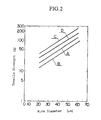
- Fig. 2 is a graph representing the relationship between the wire diameter and elongation strength of the multiple core parallel bonded wire according to a specific embodiment of the present invention.
- The copper alloy wire of the present invention is made of a copper alloy which comprises 0.01 % by weight of Ag and balance Cu and unavoidable impurities. The content of Ag is preferably in the range of 0.02 to 0.5 % by weight. The Cu may be tough pitch copper which is usually used but it is preferred to use oxygen free copper (OFC), if possible. The oxygen free copper is preferably of a purity of no lower than 99.99%.
- If the Ag content is less than 0.01 % by weight, the Ag content is insufficient and the softening temperature (recrystallization temperature) cannot be elevated sufficiently, resulting in that the resulting copper alloy wire tends to be fully softened in an enameling step or the like. For this reason, the Ag content in the wire stock is set up to no less than 0.01 % by weight. On the contrary, the Ag content exceeding 0.5 % by weight is inconvenient because not only the resistance of the conductor increases but also cost becomes higher. The oxygen content of the oxygen free copper is set up to no more than 30 ppm. If it exceeds 30 ppm, the amount of non-metal contaminants composed of oxides increases, resulting in that there tends to occur breakage of the wire upon drawing. The oxygen free copper to be used in the present invention may contain some unavoidable impurities but it is preferred that total amount of the unavoidable impurities be no more than 0.009 % by weight.
- Wires are cast from the copper alloy having the above-described composition by a conventional casting method, and then the resulting wires are processed by a conventional drawing method at a reduction ratio of no lower than 40 % to obtain multiple fine wires having a desired outer diameter, e.g., 50 µm. The drawing can be carried out dividedly in several steps. For example, wires having a diameter of 16 to 20 mm are cast and drawn to wires having a diameter of 1 to 2 mm. Then, the wires are annealed in an inert gas atmosphere to full anneal them (full softening treatment), followed by drawing them at a reduction ratio of no lower than 40 %, preferably no lower than 90 %, and more preferably no lower than 99.9 %, to obtain fine wires having an objective outer diameter, for example, 50 µm. By the term "reduction ratio of no lower than 40 %" referred to herein is meant that the reduction ratio of the wire after the final drawing step in order to obtain the objective outer diameter of the wire is no lower than 40 %. Therefore, while it is possible to carry out annealing properly in a series of drawing steps, the reduction ratio of the wire in the final drawing must be no lower than 40 %.
- If the reduction ratio as defined above is lower than 40 %, the resulting copper alloy wire cannot have a desired tensile strength after production.
- Next, the wire stock which has been subjected to the drawing at a reduction ratio of no lower than 40 % as described above is then subjected to heat treatment for half annealing. By the term "heat treatment for half annealing" herein is meant a heat treatment which is carried out on a generally cold-worked metal to a degree such that recrystallization proceeds halfway.
- Therefore, specific conditions under which the heat treatment for half annealing is carried out include temperature and time which can be set up in very wide ranges, respectively. Principally, it is sufficient to select temperature and time conditions which meet activation energy for recrystallization.
- In the present invention, the conditions, i.e., temperature and time of heat treatment for half annealing are set up so that the wire after the heat treatment for half annealing has a tensile strength of no lower than 27 kg·f/mm², preferably 27 to 35 f/mm² and an elongation of no lower than 5 %, preferably 5 to 15 %. It is preferred to carry out the heat treatment for half annealing in a non-oxidative atmosphere such as an inert gas atmosphere.
- If the copper alloy wire has a tensile strength of lower than 27 kg·f/mm², a desired bending strength cannot be obtained in the winding step and breakage of the wire tends to occur. On the other hand, if the wire has an elongation of lower than 5 %, the wound, coil-shaped wire tends to be bent back to cause so-called spring back, thus making it difficult to carry out winding. Therefore, it is necessary to carry out heat treatment for half annealing so that there can be obtained sufficient mechanical characteristics such as a tensile strength of no lower than 27 kg·f/mm² and an elongation of no lower than 5 %.
- In the present invention, it is preferred to prepare fine wires having a diameter of no larger than 90 µm, preferably no larger than 50 µm from the thus-obtained wire.
- The copper alloy wire thus obtained has a tensile strength more than is necessary and a proper elongation, and its mechanical characteristics such as tensile strength and elongation in the subsequent enameling step are not deteriorated to below values desired for cores of winding.
- Therefore, the wire causes no breakage in the step of winding and has an excellent bending resistance, resulting in that the terminals of the copper alloy wire are not bent, for example, when it is passed through the window portion of a magnetic head in the step of winding it around the ferrite core portion of the magnetic head.
- Accordingly, according to the present invention, the mechanical characteristics, such as bending resistance, tensile strength and elongation, of the wire can be improved without deteriorating its electroconductivity so that breakage and bending of the copper alloy wire in the step of winding can be prevented.
- Next, explanation will be made on the insulated electric wire of the present invention.
- The insulated electric wire of the invention comprises the above-described copper alloy wire as a conductor and an insulation layer covered on the conductor. The insulation layer can be formed by coating and baking an insulation coating material such as polyester, polyurethane, polyesterimide, polyamideimide, polyamide, polyhydantoin, polyimide, polyvinylformal, polyvinylbutyral, epoxy resins and silicone resins by conventional methods. Among the coating materials, most preferred is polyurethane in view of solderability. The thickness of the insulation layer is not limited particularly but is preferably small for the purpose of the present invention. Usually, the thickness of the insulation layer is no larger than 10 µm, preferably 5 µm.
- In addition, a protective layer may be provided on the insulation layer, if desired.
- The protective layer, which is provided in order to prevent mechanical damages and the like of the insulation layer, can be formed by coating and baking an insulation coating material such as polyester, polyurethane, polyesterimide, polyamideimide, polyamide, polyhydantoin, polyimide, polyvinylformal, polyvinylbutyral, epoxy resins and silicone resins. Instead of the protective layer, a self-lubricating layer made of polyamide or the like or a self-bonding layer made of polyvinylbutyral, polyamide or the like may be provided on the insulation layer.
- It is preferred that the insulated electric wire of the present invention be an fine electric wire also having a small outer diameter of no larger than 90 µm.
- Now, referring to the accompanying drawings, explanation will be made on the multiple core parallel bonded wire of the present invention.
- Fig. 1 illustrates a multiple core parallel bonded wire according to one embodiment of the present invention. In Fig. 1, reference numeral 1 designates an insulated wire. The insulated wire 1 includes a conductor 2 on which an insulation layer 3 is covered, and a
protective layer 4 is further covered on the insulation layer 3. - The conductor 2 is made of the above-described copper alloy wire, whose diameter is not limited particularly. However, for the purpose of the present invention, it is desirable that the diameter is no larger than 50 µm as described above, preferably no larger than 40 µm.
- On the conductor 2 is provided an insulation layer 3. The insulation layer can be formed by coating and baking an insulation coating material such as polyester, polyurethane, polyesterimide, polyamideimide, polyamide, polyhydantoin, polyimide, polyvinylformal, polyvinylbutyral, epoxy resins and silicone resins by conventional methods. Among these coating materials, most preferred is polyurethane in view of solderability. The thickness of the insulation layer 3 is not limited particularly but is preferably small for the purpose of the present invention. Usually, the thickness of the insulation layer 3 is no larger than 10 µm, preferably 5 µm.
- Furthermore, on the insulated layer 3 is provided a
protective layer 4 to form the insulated wire 1. - The
protection layer 4 is to prevent mechanical damages or the like of the insulation layer 3 and thus is not always indispensable. Theprotection layer 4 can be formed by coating and baking an insulation coating material such as polyester, polyurethane, polyesterimide, polyamideimide, polyamide, polyhydantoin, polyimide, polyvinylformal, polyvinylbutyral, epoxy resins and silicone resins by conventional methods. Among these coating materials, most preferred is polyurethane in view of solderability. Instead of theprotection layer 4, a self-lubricating layer made of nylon or the like or a self-bonding layer made of polyvinylbutyral or the like may be provided on the insulation layer 3. - Two pieces of the above-described insulated wire 1 are arranged and bonded parallel to each other with an adhesive resin composition to form a double core parallel bonded
wire 5. In Fig. 1, reference numeral 6 designates an adhesive layer 6 composed of the adhesive resin composition. As the adhesive resin composition, there can be cited, for example, polyamide, polyvinylbutyral, polysulfone, polysulfone ether, epoxy resins, phenoxy resins and the like, and thermosetting resins composed of one or more of the above-described resins and a curing agent such as an isocyanate compound, an aminoplast compound or an acid anhydride. The thickness of the adhesive layer 6 is on the order of 1 to 10 µm. Of course, the thinner the more preferred. - Double core parallel bonded
wire 5 can also be obtained without using the above-described adhesive resin composition. That is, theprotective layer 4 or the insulation layer 3 itself can be used simultaneously as an adhesive resin composition. This can be realized by properly selecting the resin composition which constitutes theprotective layer 4 or the insulation layer 3 and properly setting up the thickness thereof. - In the present invention, the parallel bonded wire may be those which can be obtained by bonding two pieces of the insulated wire 1 to each other along their longitudinal direction with interruptions or intermittently. In other words, bonded portions and non-bonded portions may appear alternately in the longitudinal direction of the double core parallel bonded wire.
- Furthermore, three or more pieces of the insulated wire 1 can be arranged parallel to each other and bonded to form a multiple core parallel bonded wire.
- The multiple core parallel bonded wire thus obtained has a high tensile strength despite its conductor diameter being small and therefore it will not break upon automatic winding or upon assembling after separation of the wire stock. In addition, despite the conductor diameter being small, the resistance of the conductor does not increase, resulting in that there is no increase in the direct current resistance even when the number of winding increases. Furthermore, the use of oxygen free copper gives rise to good high frequency characteristics, permitting transmission of signals up to 10 MHz at a low transmission loss.
- Hereafter, the invention will be explained in greater detail by concrete examples.
- Silver (Ag) was added to oxygen free copper containing 8 ppm of oxygen and 0.006 % by weight of unavoidable impurities in various proportions and the resulting copper alloys were manufactured by a dip forming method to obtain wires having an outer diameter of 16 mm. Then the wires were drawn at a reduction ratio of no lower than 99.9 % to obtain fine wires of a diameter of 40 µm using a continuous drawing machine. The fine wires were subjected to heat treatment for half annealing in an annealing furnace at 400°C to obtain conductors.
- These conductors were measured on their conductivity.
- The results obtained are shown in Table 1 below.

- The results in Table 1 revealed that when the content of silver was not larger than 0.5 % by weight, the conductivity becomes practically 100% of IACS.
-
- Silver (0.1 % by weight) was added to oxygen free copper containing 8 ppm of oxygen and 0.006 % by weight of unavoidable impurities, and the resulting copper alloy was drawn by a dip forming method to obtain a wire having a diameter of 2.6 mm. Then the wire was drawn to obtain a wire having a diameter of 50 to 1270 µm, which was then fully annealed in an annealing furnace at 600°C.
- The resulting wire was drawn at various reduction ratios to obtain fine wires having a diameter of 40 µm.
- These conductors were measured on their, tensile strength and elongation.
- The results obtained are shown in Table 2 below.

- As will be apparent from the results in Table 2, when the reduction ratio was lower than 40 %, the tensile strength of the wire before the heat treatment for half annealing was lower than 27 kg·f/mm², thus failing to give a sufficient strength.
- Silver (0.1 % by weight) was added to oxygen free copper containing 8 ppm of oxygen and 0.006 % by weight of unavoidable impurities, and the resulting copper alloy was drawn by a dip forming method to obtain a wire having a diameter of 16 mm. Then the wire was drawn to obtain a wire having a diameter of 1.27 mm, which was full annealed. Then the wire was drawn at a reduction ratio of no lower than 99.9 % to obtain an fine wire having a diameter of 40 µm.
- The fine wire was subjected to no heat treatment for half annealing (Test Example 10), subjected to heat treatment for half annealing at a temperature of 600°C (Test Example 11) or subjected to heart treatment for half annealing at a temperature of 700°C (Test Example 12) to prepare respective conductors.
- These conductors were measured on their, tensile strength and elongation.
- The results obtained are shown in Table 3 below.

- As will be apparent from the results in Table 3, the fine wire subjected to no heat treatment for half annealing showed hardening due to the drawing, resulting in that it had a decreased elongation and a poor flexibility. The fine wire subjected to heat treatment for half annealing revealed to have undergone excessive softening, thus failing to give sufficient tensile strength.
- The same conductor as obtained in Test Example 3 except that the diameter was changed to 30 αm was coated with a polyurethane coating material and baked to cover thereon a polyurethane insulation layer having a thickness of 4 µm to prepare an fine insulated wire.
- The fine insulated wire was measured on the number of pin-holes in the insulation layer, dielectric breakdown voltage, tensile strength, elongation and solderability. The number of pin-holes was expressed in number per 5 m of enameled wire according to JIS-C-3003K. The solderability was judged to be good when the wire was wetted with solder at a solder temperature of 380°C in 2 seconds.
- The results obtained are shown in Table 4 below.

- A phenoxy resin coating material was coated on the fine insulated electric wire obtained in Test Example 13 (outer diameter: 38 µm) and baked to cover thereon an adhesive layer having a thickness of 1 µm. Two pieces of the thus obtained wire were arranged parallel to each other and passed through a heating furnace at about 200°C in close contact with each other to melt the adhesive layer to bond the wires, thus preparing an fine double core parallel bonded wire.
- Various characteristics of the fine double core parallel bonded wire are shown in Table 5 below.

- The graph illustrated in Fig. 2 represents relationship between the wire diameter and tensile strength for each of an enameled wire (A) containing 0.1 % by weight of silver, an enameled wire (B) containing no silver, a double core parallel bonded wire (C) obtained from the enameled wire (A) and a double core parallel bonded wire (D) obtained from the enameled wire (B).
- The graph clearly shows that the tensile strength of the wire was significantly improved by the addition of silver.
- A copper alloy wire containing 0.01 % by weight of Ag and having a diameter of 16 mm was drawn to obtain a wire stock having a diameter of 2.6 mm. Then, after fully annealing it in a furnace of an inert gas atmosphere, the stock wire was drawn at a reduction ratio of no lower than 99.9 % to obtain an fine wire having a diameter of 40 µm. Thereafter, the fine wire was converted in a half-softened state by annealing it at a temperature of 400°C in a transfer annealing furnace of an inert gas atmosphere to prepare an Ag containing-copper alloy fine wire having a tensile strength of 35 kg·f/mm² and an elongation of 5 %.
- The procedures of Example 2 were repeated except that the speed at which the wire was transferred was made slower to make longer retention time in the transfer annealing furnace, i.e., annealing time than that in Example 2 to prepare an Ag containing-copper alloy fine wire having a tensile strength of 27 kg·f/mm² and an elongation of 14.5 %.
- A copper alloy wire containing 0.1 % by weight of Ag and having a diameter of 16 mm was drawn to obtain a wire stock having a diameter of 2.6 mm. Then, after fully annealing it in a furnace of an inert gas atmosphere, the stock wire was drawn to obtain an fine wire having a diameter of 52 µm. Further, after fully annealing it in a transfer annealing furnace of an inert gas atmosphere, the wire stock thus obtained was drawn at a reduction ratio of 40.8 % to obtain an fine wire having a diameter of 40 µm. Thereafter, the fine wire was converted in a half-softened state by annealing it at a temperature of 400°C in a transfer annealing furnace of an inert gas atmosphere to prepare an Ag containing-copper alloy fine wire having a tensile strength of 27.7 kg·f/mm² and an elongation of 11
- The procedures of Example 2 were repeated except that the speed at which the wire was transferred was made slower to make longer retention time in the transfer annealing furnace, i.e., annealing time than that in Example 3 to prepare an Ag containing-copper alloy fine wire having a tensile strength of 23.2 kg·f/mm² and an elongation of 16.5 %.
- The procedures of Example 2 were repeated except that the temperature of the transfer annealing furnace was changed to 300°C and the speed at which the wire was transferred was made slower to make longer retention time in the transfer annealing furnace, i.e., annealing time than that in Example 2 to prepare an Ag containing-copper alloy fine wire having a tensile strength of 41 kg·f/mm² and an elongation of 2.5 %.
- The procedures of Example 2 were repeated using the same annealing treatment and reduction ratio except that the starting material was changed to 99.99 % by weight (four nine) oxygen free copper wire (diameter: 16 mm) and the temperature of the transfer annealing furnace was changed to 300°C to prepare a pure copper fine wire having a tensile strength of 28 kg·f/mm² and an elongation of 10 %.
- The procedures of Example 2 were repeated using the same full annealing treatment and reduction ratio except that the starting material was changed to 0.005 % by weight Ag containing-copper alloy rod (diameter: 16 mm) and the temperature of the transfer annealing furnace was changed to 300°C to prepare an Ag containing-copper alloy fine wire having a tensile strength of 32 kg·f/mm² and an elongation of 7 %.
- The same copper alloy wire as used in Example 4 was drawn to obtain a wire stock having a diameter of 2.6 mm. Then, after fully annealing it in a furnace of an inert gas atmosphere, the stock wire was drawn to obtain a wire having a diameter of 43 µm. Further, after fully annealing it in a transfer annealing furnace of an inert gas atmosphere, the wire thus obtained was drawn at a reduction ratio of 13.5 % to obtain an Ag containing-copper alloy fine wire having a diameter of 40 µm and having mechanical characteristics of a tensile strength of 25 kg.f/mm2 and an elongation of 18 %.
- The copper alloy fine wires (including copper fine wires) obtained in Examples 2 to 4 and Comparative Examples 1 to 5 were measured on their conductivity (% IACS). Then, after coating enamel on the periphery of the copper or copper alloy wire wires and baking, they were examined if they were softened. Furthermore, each of the resulting wire wires was wound around the ferrite core portion of a magnetic head and degree of easiness of winding was examined. The results obtained are shown in Table 6 below.


- From Table 6 above, it will be clear that the copper alloy fine wires having high conductivities as high as 99 to 100 % IACS showed no softening after the baking of enamel and were wound easily.
- On the other hand, the copper alloy or pure-copper fine wires obtained in Comparative Examples 1 to 5 had sufficiently high conductivities of 99 to 101 % IACS. However, the copper alloy fine wire obtained in Comparative Example 1 in which the transfer annealing time was longer than Example 1 and that obtained in Comparative Example 5 in which the reduction ratio was as low as 13.5 % did not show softening after the baking enamel but had insufficient tensile strengths in the winding step, resulting in that they had poor bending resistances and thus were difficult to be wound.
- Also, the copper alloy fine wire obtained in Comparative Example 2 in which the transfer annealing time was shorter than Example 2 did not show softening after the baking enamel but caused spring-back because of insufficient elongation during he winding step, thus making it difficult to wind it. Furthermore, the pure copper fine wire containing no Ag obtained in Comparative Example 3 and the copper alloy fine wire with an Ag content of 0.005 % by weight obtained in Comparative Example 4 suffered from softening due to the baking of enamel to decrease their tensile strengths, resulting in that their bending resistances were poor and therefore it was difficult to wind them.
Claims (13)
- A copper alloy wire having a composition composed of no less than 0.01 % by weight of Ag and balance Cu and unavoidable impurities, wherein said copper alloy wire has been prepared by drawing a wire stock having said composition at a reduction ratio of no lower than 40 % and subjecting said wire stock to heat treatment for half annealing to have a tensile strength of no lower than 27 kg·f/mm² and an elongation of 5 %.
- A copper alloy wire as claimed in Claim 1, wherein said copper alloy wire has a tensile strength of 27 to 35 kg·f/mm².
- A copper alloy wire as claimed in Claim 1, wherein said copper alloy wire has an elongation of 5 to 15 %.
- A copper alloy wire as claimed in Claim 1∼3, wherein oxygen free copper is used as Cu.
- A copper alloy wire as claimed in Claim 1∼4, wherein said copper alloy wire has an outer diameter of no larger than 90 µm.
- A copper alloy wire as claimed in Claim 5, wherein said copper alloy wire has an outer diameter of no larger than 40 µm.
- An insulated electric wire having a copper alloy wire as a conductor and an insulation layer covering the conductor, wherein said copper alloy wire has a composition composed of no less than 0.01 % by weight of Ag and balance Cu and unavoidable impurities, and wherein said copper alloy wire has been prepared by drawing a wire stock having said composition at a reduction ratio of no lower than 40 % and subjecting said wire stock to heat treatment for half annealing to have a tensile strength of no lower than 27 kg·f/mm² and an elongation of 5 %.
- An insulated electric wire as claimed in Claim 7, wherein said insulated electric wire is an fine electric wire having a final diameter of no larger than 90 µm.
- An insulated electric wire as claimed in Claim 7, 8, wherein said insulation layer is composed of polyurethane.
- An insulated electric wire as claimed in Claim 7∼9, further comprising an adhesive layer provided on said insulation layer.
- A multiple core parallel bonded wire comprising two or more insulated electric wires bonded parallel to each other as cores, wherein said insulated electric wires each are an insulated electric wire having a copper alloy wire as a conductor and an insulation layer covering the conductor, wherein said copper alloy wire has a composition composed of no less than 0.01 % by weight of Ag and balance Cu and unavoidable impurities, and wherein said copper alloy wire has been prepared by drawing a wire stock having said composition at a reduction ratio of no lower than 40 % and subjecting said wire stock to heat treatment for half annealing to have a tensile strength of no lower than 27 kg·f/mm² and an elongation of 5 %.
- A multiple core parallel bonded wire as claimed in Claim 11, further comprising a protective layer provided on said insulation layer.
- A multiple core parallel bonded wire as claimed in Claim 11, 12, wherein said two or more insulated wires are bonded to each other intermittently in a longitudinal direction.
Applications Claiming Priority (4)
| Application Number | Priority Date | Filing Date | Title |
|---|---|---|---|
| JP2022818A JPH03230415A (en) | 1990-02-01 | 1990-02-01 | Copper alloy wire rod |
| JP22818/90 | 1990-02-01 | ||
| JP334098/90 | 1990-11-30 | ||
| JP33409890 | 1990-11-30 |
Publications (2)
| Publication Number | Publication Date |
|---|---|
| EP0440184A1 true EP0440184A1 (en) | 1991-08-07 |
| EP0440184B1 EP0440184B1 (en) | 1996-09-18 |
Family
ID=26360099
Family Applications (1)
| Application Number | Title | Priority Date | Filing Date |
|---|---|---|---|
| EP91101193A Expired - Lifetime EP0440184B1 (en) | 1990-02-01 | 1991-01-30 | Copper alloy wire, and insulated electric wires and multiple core parallel bonded wires made of the same |
Country Status (6)
| Country | Link |
|---|---|
| US (1) | US5106701A (en) |
| EP (1) | EP0440184B1 (en) |
| KR (1) | KR950007086B1 (en) |
| DE (1) | DE69122135D1 (en) |
| MY (1) | MY106101A (en) |
| SG (1) | SG68581A1 (en) |
Cited By (3)
| Publication number | Priority date | Publication date | Assignee | Title |
|---|---|---|---|---|
| SG83129A1 (en) * | 1999-05-17 | 2001-09-18 | Hitachi Cable | Extra fine copper wire and process for producing the same |
| EP1145779A3 (en) * | 2000-04-11 | 2002-07-17 | Mitsubishi Materials Corporation | Adhesion-resistant oxygen-free copper wire rod |
| WO2008096947A1 (en) * | 2007-02-07 | 2008-08-14 | Ls Cable, Ltd. | Micro coaxial cable for high bending performance |
Families Citing this family (20)
| Publication number | Priority date | Publication date | Assignee | Title |
|---|---|---|---|---|
| US5646812A (en) * | 1995-08-28 | 1997-07-08 | Porta Systems Corp. | Telephone line surge protector module with fast-acting, high resistance heat coil assembly |
| US7544886B2 (en) * | 2005-12-20 | 2009-06-09 | Hitachi Cable, Ltd. | Extra-fine copper alloy wire, extra-fine copper alloy twisted wire, extra-fine insulated wire, coaxial cable, multicore cable and manufacturing method thereof |
| KR100798493B1 (en) * | 2006-07-13 | 2008-01-28 | 고려용접봉 주식회사 | Plating solid wire assembly for gas shield arc welding and welding method using the same |
| US20110193442A1 (en) * | 2007-10-12 | 2011-08-11 | Kengo Yoshida | Insulated wire, electrical coil using the insulated wire, and motor |
| JP5476649B2 (en) * | 2008-04-03 | 2014-04-23 | 住友電工ウインテック株式会社 | Insulated wire |
| US8658576B1 (en) | 2009-10-21 | 2014-02-25 | Encore Wire Corporation | System, composition and method of application of same for reducing the coefficient of friction and required pulling force during installation of wire or cable |
| JO3139B1 (en) | 2011-10-07 | 2017-09-20 | Shell Int Research | Formation of insulated conductors using a final reduction step after heat treatment. |
| CN104137191A (en) * | 2011-12-28 | 2014-11-05 | 矢崎总业株式会社 | Ultrafine conductor material, ultrafine conductor, method for preparing ultrafine conductor, and ultrafine electrical wire |
| US9352371B1 (en) | 2012-02-13 | 2016-05-31 | Encore Wire Corporation | Method of manufacture of electrical wire and cable having a reduced coefficient of friction and required pulling force |
| US11328843B1 (en) | 2012-09-10 | 2022-05-10 | Encore Wire Corporation | Method of manufacture of electrical wire and cable having a reduced coefficient of friction and required pulling force |
| US10056742B1 (en) | 2013-03-15 | 2018-08-21 | Encore Wire Corporation | System, method and apparatus for spray-on application of a wire pulling lubricant |
| KR102105213B1 (en) * | 2013-11-20 | 2020-04-28 | 엘에스전선 주식회사 | Winding alloy wire for fuse choke coil |
| FR3024798B1 (en) * | 2014-08-06 | 2018-01-12 | Nexans | ELECTRICAL CONDUCTOR FOR AERONAUTICAL APPLICATIONS |
| SG10201408305YA (en) * | 2014-12-11 | 2016-07-28 | Heraeus Deutschland Gmbh & Co Kg | Bonding wire for a semiconductor device |
| SG10201408586XA (en) * | 2014-12-22 | 2016-07-28 | Heraeus Materials Singapore Pte Ltd | Corrosion and moisture resistant bonding wire |
| JP2016162676A (en) * | 2015-03-04 | 2016-09-05 | 住友電気工業株式会社 | Flat cable |
| SG10201509913XA (en) * | 2015-12-02 | 2017-07-28 | Heraeus Materials Singapore Pte Ltd | Silver alloyed copper wire |
| WO2017151737A1 (en) * | 2016-03-03 | 2017-09-08 | H.C. Starck Inc. | Fabricaton of metallic parts by additive manufacturing |
| JP7393743B2 (en) * | 2020-06-30 | 2023-12-07 | 住友電装株式会社 | Electric wires and electric wires with terminals |
| EP4538408A1 (en) * | 2022-06-08 | 2025-04-16 | SWCC Corporation | Electrical-property-inspection conductor wire and manufacturing method therefor |
Citations (2)
| Publication number | Priority date | Publication date | Assignee | Title |
|---|---|---|---|---|
| DE975448C (en) * | 1952-05-28 | 1961-11-30 | Siemens Ag | Short-circuit ring for magnets of electromagnetic switching devices, especially contactors |
| EP0029888A1 (en) * | 1979-11-19 | 1981-06-10 | International Business Machines Corporation | Method of producing a conductive wire |
Family Cites Families (7)
| Publication number | Priority date | Publication date | Assignee | Title |
|---|---|---|---|---|
| GB567603A (en) * | 1943-08-26 | 1945-02-22 | Enfield Rolling Mills Ltd | Copper base alloys |
| US2559031A (en) * | 1943-08-26 | 1951-07-03 | Enfield Rolling Mills Ltd | Copper base alloys |
| US4059437A (en) * | 1975-07-02 | 1977-11-22 | Phelps Dodge Industries, Inc. | Oxygen-free copper product and process |
| JPS6043905B2 (en) * | 1979-09-14 | 1985-10-01 | 三菱マテリアル株式会社 | Manufacturing method of highly conductive heat-resistant copper alloy material |
| JPS5770244A (en) * | 1980-10-15 | 1982-04-30 | Furukawa Electric Co Ltd:The | Heat-resistant and anticorrosive copper alloy for electric conduction |
| SE449784B (en) * | 1985-09-13 | 1987-05-18 | Scandinavian Solar Ab | PARTY ARRANGEMENTS |
| US4734254A (en) * | 1986-12-15 | 1988-03-29 | The Nippert Company | Enhanced machining anneal resistant copper alloy |
-
1991
- 1991-01-25 US US07/645,819 patent/US5106701A/en not_active Expired - Fee Related
- 1991-01-28 KR KR1019910001398A patent/KR950007086B1/en not_active Expired - Fee Related
- 1991-01-30 EP EP91101193A patent/EP0440184B1/en not_active Expired - Lifetime
- 1991-01-30 SG SG1996009414A patent/SG68581A1/en unknown
- 1991-01-30 DE DE69122135T patent/DE69122135D1/en not_active Expired - Lifetime
- 1991-01-31 MY MYPI91000147A patent/MY106101A/en unknown
Patent Citations (2)
| Publication number | Priority date | Publication date | Assignee | Title |
|---|---|---|---|---|
| DE975448C (en) * | 1952-05-28 | 1961-11-30 | Siemens Ag | Short-circuit ring for magnets of electromagnetic switching devices, especially contactors |
| EP0029888A1 (en) * | 1979-11-19 | 1981-06-10 | International Business Machines Corporation | Method of producing a conductive wire |
Non-Patent Citations (2)
| Title |
|---|
| Patent Office of Japan &JPA1313121(SHOWA ELECTRIC) * |
| Patent Office of Japan &JPA62118737(TOSHIBA) * |
Cited By (5)
| Publication number | Priority date | Publication date | Assignee | Title |
|---|---|---|---|---|
| SG83129A1 (en) * | 1999-05-17 | 2001-09-18 | Hitachi Cable | Extra fine copper wire and process for producing the same |
| EP1145779A3 (en) * | 2000-04-11 | 2002-07-17 | Mitsubishi Materials Corporation | Adhesion-resistant oxygen-free copper wire rod |
| US6682824B1 (en) | 2000-04-11 | 2004-01-27 | Mitsubishi Materials Corporation | Adhesion-resistant oxygen-free roughly drawn copper wire and method and apparatus for making the same |
| WO2008096947A1 (en) * | 2007-02-07 | 2008-08-14 | Ls Cable, Ltd. | Micro coaxial cable for high bending performance |
| US8242358B2 (en) | 2007-02-07 | 2012-08-14 | Ls Cable & System Ltd. | Micro coaxial cable for high bending performance |
Also Published As
| Publication number | Publication date |
|---|---|
| KR920000090A (en) | 1992-01-10 |
| SG68581A1 (en) | 1999-11-16 |
| MY106101A (en) | 1995-03-31 |
| DE69122135D1 (en) | 1996-10-24 |
| US5106701A (en) | 1992-04-21 |
| KR950007086B1 (en) | 1995-06-30 |
| EP0440184B1 (en) | 1996-09-18 |
Similar Documents
| Publication | Publication Date | Title |
|---|---|---|
| US5106701A (en) | Copper alloy wire, and insulated electric wires and multiple core parallel bonded wires made of the same | |
| US7544886B2 (en) | Extra-fine copper alloy wire, extra-fine copper alloy twisted wire, extra-fine insulated wire, coaxial cable, multicore cable and manufacturing method thereof | |
| JP4762474B2 (en) | Multilayer insulated wire and transformer using the same | |
| JP4288844B2 (en) | Extra fine copper alloy wire | |
| US5118906A (en) | Wire conductors for automobiles | |
| JPH01289021A (en) | Manufacture of copper clad steel stranded wire | |
| US3097965A (en) | Conductive wire coating alloys, wires coated therewith and process for improving solderability therefor | |
| JPH0352523B2 (en) | ||
| JPH06203639A (en) | Electric cable conductor used for wiring and manufacture thereof | |
| JPH04341708A (en) | Ultra-fine multi-core parallel adhesive wire | |
| JP3050554B2 (en) | Magnet wire | |
| JP4762701B2 (en) | Electric wire conductor for wiring and electric wire for wiring using the same | |
| JPH0656722B2 (en) | High frequency wire | |
| JPH0689621A (en) | Manufacturing method of highly conductive and high strength stranded wire | |
| JP2000169918A (en) | Ultrafine wire and method of manufacturing the same | |
| JPS613858A (en) | Copper alloy having superior heat resistance, workability and electric conductivity | |
| JPH02278608A (en) | Superfine enamel wire | |
| US4859258A (en) | Method of manufacturing a flexible electric cable including a conductor comprising a plurality of fine strands of aluminum or aluminum alloy | |
| JPS6242977B2 (en) | ||
| RU238748U1 (en) | ELECTRIC WIRE | |
| JPH0644413B2 (en) | Copper alloy composite wire for extra fine wire | |
| JPS6030043B2 (en) | Automotive wire conductor | |
| JPS6256218B2 (en) | ||
| JPH03230415A (en) | Copper alloy wire rod | |
| JPH06290639A (en) | High-strength and high-conductivity flex-resistant composite wire |
Legal Events
| Date | Code | Title | Description |
|---|---|---|---|
| PUAI | Public reference made under article 153(3) epc to a published international application that has entered the european phase |
Free format text: ORIGINAL CODE: 0009012 |
|
| AK | Designated contracting states |
Kind code of ref document: A1 Designated state(s): DE GB IT |
|
| 17P | Request for examination filed |
Effective date: 19910926 |
|
| 17Q | First examination report despatched |
Effective date: 19940816 |
|
| GRAH | Despatch of communication of intention to grant a patent |
Free format text: ORIGINAL CODE: EPIDOS IGRA |
|
| GRAH | Despatch of communication of intention to grant a patent |
Free format text: ORIGINAL CODE: EPIDOS IGRA |
|
| GRAA | (expected) grant |
Free format text: ORIGINAL CODE: 0009210 |
|
| AK | Designated contracting states |
Kind code of ref document: B1 Designated state(s): DE GB IT |
|
| PG25 | Lapsed in a contracting state [announced via postgrant information from national office to epo] |
Ref country code: IT Free format text: LAPSE BECAUSE OF FAILURE TO SUBMIT A TRANSLATION OF THE DESCRIPTION OR TO PAY THE FEE WITHIN THE PRESCRIBED TIME-LIMIT;WARNING: LAPSES OF ITALIAN PATENTS WITH EFFECTIVE DATE BEFORE 2007 MAY HAVE OCCURRED AT ANY TIME BEFORE 2007. THE CORRECT EFFECTIVE DATE MAY BE DIFFERENT FROM THE ONE RECORDED. Effective date: 19960918 |
|
| REF | Corresponds to: |
Ref document number: 69122135 Country of ref document: DE Date of ref document: 19961024 |
|
| PG25 | Lapsed in a contracting state [announced via postgrant information from national office to epo] |
Ref country code: DE Effective date: 19961219 |
|
| PLBE | No opposition filed within time limit |
Free format text: ORIGINAL CODE: 0009261 |
|
| STAA | Information on the status of an ep patent application or granted ep patent |
Free format text: STATUS: NO OPPOSITION FILED WITHIN TIME LIMIT |
|
| 26N | No opposition filed | ||
| PGFP | Annual fee paid to national office [announced via postgrant information from national office to epo] |
Ref country code: GB Payment date: 20010124 Year of fee payment: 11 |
|
| REG | Reference to a national code |
Ref country code: GB Ref legal event code: IF02 |
|
| PG25 | Lapsed in a contracting state [announced via postgrant information from national office to epo] |
Ref country code: GB Free format text: LAPSE BECAUSE OF NON-PAYMENT OF DUE FEES Effective date: 20020130 |
|
| GBPC | Gb: european patent ceased through non-payment of renewal fee |
Effective date: 20020130 |