EP0440525A1 - Steuervorrichtung zum elektrischen Speisen von mehreren elektrischen Geräten von einer Gleichstromquelle aus - Google Patents
Steuervorrichtung zum elektrischen Speisen von mehreren elektrischen Geräten von einer Gleichstromquelle aus Download PDFInfo
- Publication number
- EP0440525A1 EP0440525A1 EP91400158A EP91400158A EP0440525A1 EP 0440525 A1 EP0440525 A1 EP 0440525A1 EP 91400158 A EP91400158 A EP 91400158A EP 91400158 A EP91400158 A EP 91400158A EP 0440525 A1 EP0440525 A1 EP 0440525A1
- Authority
- EP
- European Patent Office
- Prior art keywords
- local
- switch
- central
- power supply
- transistor
- Prior art date
- Legal status (The legal status is an assumption and is not a legal conclusion. Google has not performed a legal analysis and makes no representation as to the accuracy of the status listed.)
- Granted
Links
Images


Classifications
-
- H—ELECTRICITY
- H02—GENERATION; CONVERSION OR DISTRIBUTION OF ELECTRIC POWER
- H02J—ELECTRIC POWER NETWORKS; CIRCUIT ARRANGEMENTS OR SYSTEMS FOR SUPPLYING OR DISTRIBUTING ELECTRIC POWER; SYSTEMS FOR STORING ELECTRIC ENERGY
- H02J13/00—Circuit arrangements for providing remote monitoring or remote control of equipment in a power distribution network
- H02J13/14—Circuit arrangements for providing remote monitoring or remote control of equipment in a power distribution network the power network being locally controlled, e.g. home energy management systems [HEMS]
-
- H—ELECTRICITY
- H02—GENERATION; CONVERSION OR DISTRIBUTION OF ELECTRIC POWER
- H02J—ELECTRIC POWER NETWORKS; CIRCUIT ARRANGEMENTS OR SYSTEMS FOR SUPPLYING OR DISTRIBUTING ELECTRIC POWER; SYSTEMS FOR STORING ELECTRIC ENERGY
- H02J13/00—Circuit arrangements for providing remote monitoring or remote control of equipment in a power distribution network
- H02J13/18—Circuit arrangements for providing remote monitoring or remote control of equipment in a power distribution network characterised by the remotely-controlled equipment, e.g. converters or transformers
- H02J13/34—Circuit arrangements for providing remote monitoring or remote control of equipment in a power distribution network characterised by the remotely-controlled equipment, e.g. converters or transformers the equipment being switches, relays or circuit breakers
-
- B—PERFORMING OPERATIONS; TRANSPORTING
- B60—VEHICLES IN GENERAL
- B60R—VEHICLES, VEHICLE FITTINGS, OR VEHICLE PARTS, NOT OTHERWISE PROVIDED FOR
- B60R16/00—Electric or fluid circuits specially adapted for vehicles and not otherwise provided for; Arrangement of elements of electric or fluid circuits specially adapted for vehicles and not otherwise provided for
- B60R16/02—Electric or fluid circuits specially adapted for vehicles and not otherwise provided for; Arrangement of elements of electric or fluid circuits specially adapted for vehicles and not otherwise provided for electric constitutive elements
- B60R16/03—Electric or fluid circuits specially adapted for vehicles and not otherwise provided for; Arrangement of elements of electric or fluid circuits specially adapted for vehicles and not otherwise provided for electric constitutive elements for supply of electrical power to vehicle subsystems or for
-
- H—ELECTRICITY
- H02—GENERATION; CONVERSION OR DISTRIBUTION OF ELECTRIC POWER
- H02J—ELECTRIC POWER NETWORKS; CIRCUIT ARRANGEMENTS OR SYSTEMS FOR SUPPLYING OR DISTRIBUTING ELECTRIC POWER; SYSTEMS FOR STORING ELECTRIC ENERGY
- H02J2105/00—Networks for supplying or distributing electric power characterised by their spatial reach or by the load
- H02J2105/30—Networks for supplying or distributing electric power characterised by their spatial reach or by the load the load networks being external to vehicles, i.e. exchanging power with vehicles
- H02J2105/33—Networks for supplying or distributing electric power characterised by their spatial reach or by the load the load networks being external to vehicles, i.e. exchanging power with vehicles exchanging power with road vehicles
-
- Y—GENERAL TAGGING OF NEW TECHNOLOGICAL DEVELOPMENTS; GENERAL TAGGING OF CROSS-SECTIONAL TECHNOLOGIES SPANNING OVER SEVERAL SECTIONS OF THE IPC; TECHNICAL SUBJECTS COVERED BY FORMER USPC CROSS-REFERENCE ART COLLECTIONS [XRACs] AND DIGESTS
- Y02—TECHNOLOGIES OR APPLICATIONS FOR MITIGATION OR ADAPTATION AGAINST CLIMATE CHANGE
- Y02P—CLIMATE CHANGE MITIGATION TECHNOLOGIES IN THE PRODUCTION OR PROCESSING OF GOODS
- Y02P80/00—Climate change mitigation technologies for sector-wide applications
- Y02P80/10—Efficient use of energy, e.g. using compressed air or pressurized fluid as energy carrier
- Y02P80/14—District level solutions, i.e. local energy networks
-
- Y—GENERAL TAGGING OF NEW TECHNOLOGICAL DEVELOPMENTS; GENERAL TAGGING OF CROSS-SECTIONAL TECHNOLOGIES SPANNING OVER SEVERAL SECTIONS OF THE IPC; TECHNICAL SUBJECTS COVERED BY FORMER USPC CROSS-REFERENCE ART COLLECTIONS [XRACs] AND DIGESTS
- Y02—TECHNOLOGIES OR APPLICATIONS FOR MITIGATION OR ADAPTATION AGAINST CLIMATE CHANGE
- Y02P—CLIMATE CHANGE MITIGATION TECHNOLOGIES IN THE PRODUCTION OR PROCESSING OF GOODS
- Y02P80/00—Climate change mitigation technologies for sector-wide applications
- Y02P80/10—Efficient use of energy, e.g. using compressed air or pressurized fluid as energy carrier
- Y02P80/15—On-site combined power, heat or cool generation or distribution, e.g. combined heat and power [CHP] supply
Definitions
- the present invention relates to a device for controlling the electrical supply of several local electrical appliances from a single central source of direct current, comprising a central bistable switch connected between a first terminal of said source and the supply lines of said local electrical appliances and a central resistance connected in parallel to said central switch, each local electrical appliance comprising a local resistance and at least one control switch in series connected between its supply line and the second terminal of said source, each local resistance forming with the central resistance a voltage divider bridge, the midpoint of which is connected to a central detector controlling said central switch, each local electrical appliance supplying the central detector with reopening information of the central supply switch.
- the invention applies in particular to the supply of the various electrical appliances of a motor vehicle from a central supply unit.
- the central unit remains in standby state and can be activated by actuation of the local control switch by means of the aforementioned divider bridge, the voltage of which median is detected by the central detector which "activates" the central unit in the case of a request expressed by the actuation of a local control switch.
- This device makes it possible to control the supply of local electrical appliances only when one of them is used; this makes it possible to minimize consumption losses when none of the electrical devices are used.
- the present invention relates to a supply control device of the aforementioned type which makes it possible to further reduce the leakage currents during the standby state.
- each local electrical appliance comprises means for isolating said local appliance from its supply line, means for suppressing the current flowing in said resistor local and means for detecting the closing of the central bistable switch which control the closing of said isolation means and the opening of said current suppression means when the central bistable switch closes.
- each local electrical appliance there is provided a local circuit breaker connected in series with said local resistance and said control switch, a local contactor connected in the supply line downstream of said control switch and local resistance and a local detector connected upstream of said local contactor and controlling said local breaker and contactor.
- actuation of the control switch causes, as described above, the closing of the central switch via the detector central; the local detector reacting to the voltage difference applied to the device then controls the closing of the local contactor and the opening of the local breaker, which, on the one hand, ensures the supply of the electrical device and, on the other hand, immediately interrupts the flow of current through the local resistance, even if the control switch remains actuated.
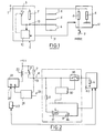
- Fig.1 describes a device for controlling the electrical supply of local electrical devices from a central control unit 12.
- the power source is a direct current source of which the positive pole is seen in 1 and the negative pole is connected to ground, as is the case with most motor vehicles.
- the central unit 2 comprises a central switch 3 which connects the positive supply terminal 1 to different supply lines 4 each supplying a local electrical appliance 12 such as, in the case of a motor vehicle, a wiper, an alarm, an electric window regulator, etc.
- the impedance of this electrical device is shown in 6. The switch is not closed only when local electrical appliances are used.
- a first central resistance 7 is provided in parallel on the central switch 3 and, in each local electrical appliance, a local resistance 8 and a local control switch 9 connected in series between the supply line 4 of the considered device and ground.
- a central detector 10 is connected to the midpoint 13 of the voltage divider constituted by the resistors 7 and 8 and this detector 10 controls the central switch 3; this detector 10 also receives, via an information line or bus 11, operating information originating from the local electrical appliance 12.
- the control device which has just been described is shown in the standby state, that is to say that the central switch 3 is open as well as the local control switch 9.
- the detector 10 which controls the closing of the central switch 3.
- the detector 10 receives, via the bus 11, from the local device, information for stopping operation of the latter, it commands the reopening of the central switch 3.
- V is the voltage of the power source
- Z the impedance of the local electrical device 12 and R7 the value of resistance 7.
- Fig.2 schematically illustrates a power control device according to the present invention.
- the switch 3 consists of the contact 21 of a relay 22 which is controlled by a flip-flop 23 which receives an activation signal supplied by a comparator 24 comparing the voltage at the midpoint of the divider bridge with a voltage reference provided at 25.
- the flip-flop 23 receives on its reset input 26 a signal to return to the standby state. This signal is produced by a central unit 20 which receives via the bus 11 operating information coming from the local electrical appliances in use.
- the control switch 9 In the local device there is the control switch 9, the resistor 8 in series and the proper impedance 6 of the device considered.
- a breaker 27 that is to say a monostable device closed in the rest position;
- a contactor 28 downstream of the circuit constituted by the resistor 8 and the switch 9, a contactor 28, that is to say a monostable device which is open in the rest position;
- a local detector 30 is connected upstream of the contactor 28.
- the voltage of the direct source is then applied to the supply line 4, which is detected by the local detector 30 which acts at the both on the contactor 28 to obtain its closure, which causes the supply of the device 40, and on the switch 27 which opens, which eliminates the consumption in the branch formed by the resistor 8 and the control switch 9; even if we continue to close this local control switch 9, the current in the aforementioned branch is interrupted immediately after the wakeup of the central unit.
- the flip-flop 23 When the flip-flop 23 receives a reset command, the relay 22 is no longer supplied with power and the switch 21 is open, which puts the central unit in standby state and the local detector 30 no longer receiving the voltage from the power source deactivates the contactor 28 which returns to the open position and the switch 27 which returns to the closed position; the assembly then returned to the waking state.
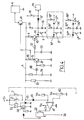
- Fig.3 shows a practical embodiment of a device according to the present invention.
- the comparator consists of an operational amplifier 41 whose positive input receives a reference voltage supplied by a potentiometer 42 and which receives, on its negative input terminal, by by means of a diode mounted in reverse 43, the voltage of the midpoint 13 of the voltage divider constituted by the resistors 7 and 8.
- the output of the flip-flop 23 controls the relay 22 via a transistor 44, such as a MOSFET.
- the voltage Vcc applied to the potentiometer 42 can be a stabilized voltage supplied for example by a Zener diode or the voltage of the battery protected against overvoltage.
- the breaker 27 is constituted by an NPN transistor 45 and that the contactor 28 is constituted by a PNP transistor 46.
- the detector 30 essentially comprises an NPN transistor 47 and a resistor 29 constituting with the resistor 7 of the central unit another dividing bridge. The transistor 47 and the resistor 29 are each connected between the line 4 and the ground.
- the divider bridge constituted by the resistors 7 and 29 supplies, in the standby state, a voltage V1 which is lower than the reverse voltage of a Zener diode 48 connected in the basic circuit of the transistor 47, so as to block this transistor 47 when in the standby state.
- the base of transistor 45 is controlled by resistors 49, 51 and 52 so that this transistor 45 is ready to saturate when switch 9 closes.
- the transistor 46 whose base is connected to the positive voltage V1 is blocked, which isolates the local device and in particular its impedance 6.
- the switch 9 which can for example be a door leaf contact, a headlight call, horn contact, etc.
- the transistor 45 is immediately saturated, which causes the resistor to be supplied 8 of the divider bridge.
- the variation of the voltage at midpoint 13 is detected by the operational amplifier 41 which acts on the flip-flop 23 to control the supply of the relay 22, which causes the switch 21 to close.
- the resistor 8 can be chosen to be of low value for example 3 Ohms so that the voltage at point 13 of the divider falls to an almost zero value.
- a capacitor 53 connected between ground and the collector of transistor 47 was, during standby, charged to potential V1 and its discharge through resistors 49, 51 and 52 will allow the saturation of transistor 45 to be maintained and, consequently, to maintain the voltage on line 4 at its low level (0.5 V for example) for a few hundred microseconds.
- the voltage on the supply line 4 changes to a value close to the voltage of the vehicle battery which is greater than the reverse voltage of the Zener diode 48, which saturates the transistor 47 and, as a result, saturates the transistor 46 and blocks the transistor 45.
- the local electrical apparatus is then supplied by the battery voltage and can therefore operate normally.
- the large current flowing through the resistance 8 of low value and the switch 9 is then interrupted.
- a capacitor 54 connected between ground and the Zener diode 48 prolongs the blocking of the transistor 47 when the switch 21 is closed in order to circulate a large current, for example 500 mA in 500 microseconds in the switch 9, which makes it possible to deoxidize the contacts of this switch.
- a resistor 55 is provided, connected between the supply line 4 upstream of the transistor 46 and the emitter of the transistor 45, this makes it possible to circulate a current in the switch 9 even when transistor 45 is blocked.
- the circulation of this current in the switch 9 allows, via a circuit consisting of a capacitor 56 connected in parallel to the switch 9 and a diode 57 to create an information signal from a logic voltage, for example 5V applied to a resistor 58, the other terminal of which is connected to the diode 57.
- the information signal thus obtained at 59 is sent by the information bus to the central station, in particular to provide a on-off control signal.
- Fig.3 shows a device according to the invention which can be used in the case where the local electrical device has only one control switch 9.
- Fig.4 shows an alternative embodiment which allows the use with a local electrical appliance comprising several control switches 9.
- each switch 9, 9 ′, ..., 9 n for a current holding resistor 55, 55 ′, ..., 55 n and a circuit for forming the information signal 56-59, 56′-59 ′, ..., 56 n -59 n . Furthermore, to prevent all the information signal forming circuits from being activated when a single control switch is closed, there is, upstream of each switch 9, between the latter and the emitter of transistor 45, a diode 50, 50 ', ..., 50 n which prevents the flow of a current to ground in the resistors 55 whose corresponding control switch has not been actuated.
- FIG. 5 represents another variant consisting in introducing into the circuit of FIG. 4 a device making it possible to obtain standby even if one of the switches of a local device comprising several control switches remains closed. This eliminates the supply of stations 6 and in particular, for example, that of the ceiling light when, the vehicle being in the garage, one of the doors remains open.
- This device essentially comprises two NPN transistors 61 and 62; the first transistor 61 is connected in series with a resistor 63 between line 4 and ground; the collector of this transistor 61 controls, via a resistor 64, the base of the transistor 62 whose emitter is connected to ground and the collector to the base of the transistor 45.
- the base of the transistor 61 is connected to a resistor 65 which is itself connected, via a diode 66 to the upstream contact of each of the local switches 9 to 9 n considered, that is to say to the emitter of transistor 45, by the diode 50 to 50 n .
- the switches can for example be constituted by the door leaf contacts of a motor vehicle.
- a blocking circuit for the local breaker 45 is thus produced, this blocking circuit being controlled by the voltage across each of the control switches 9, 9 ′, ..., 9 n .
- a special circuit can be provided for a priority local switch, for example a local switch for controlling the distress signal; this switch 9 p is connected directly, via a diode 68, to the base of transistor 62. As a result, the closing of this switch 9 p blocks transistor 62 which in turn allows transistor 45 to saturate.
- a priority control circuit is thus produced for the switch 9 p , a circuit which acts on the transistor 45 via the transistor 62.
Landscapes
- Engineering & Computer Science (AREA)
- Power Engineering (AREA)
- Remote Monitoring And Control Of Power-Distribution Networks (AREA)
- Direct Current Feeding And Distribution (AREA)
Applications Claiming Priority (2)
| Application Number | Priority Date | Filing Date | Title |
|---|---|---|---|
| FR9000996A FR2657733B1 (fr) | 1990-01-29 | 1990-01-29 | Dispositif de commande de l'alimentation electrique de plusieurs appareils electriques a partir d'une source de courant continu. |
| FR9000996 | 1990-01-29 |
Publications (2)
| Publication Number | Publication Date |
|---|---|
| EP0440525A1 true EP0440525A1 (de) | 1991-08-07 |
| EP0440525B1 EP0440525B1 (de) | 1993-11-24 |
Family
ID=9393181
Family Applications (1)
| Application Number | Title | Priority Date | Filing Date |
|---|---|---|---|
| EP91400158A Expired - Lifetime EP0440525B1 (de) | 1990-01-29 | 1991-01-24 | Steuervorrichtung zum elektrischen Speisen von mehreren elektrischen Geräten von einer Gleichstromquelle aus |
Country Status (5)
| Country | Link |
|---|---|
| US (1) | US5198697A (de) |
| EP (1) | EP0440525B1 (de) |
| JP (1) | JP2993776B2 (de) |
| DE (1) | DE69100664T2 (de) |
| FR (1) | FR2657733B1 (de) |
Families Citing this family (6)
| Publication number | Priority date | Publication date | Assignee | Title |
|---|---|---|---|---|
| FR2685565B1 (fr) * | 1991-12-18 | 1994-05-13 | Peugeot Automobiles | Boitier de servitude electrique notamment pour vehicule automobile. |
| US5684441A (en) * | 1996-02-29 | 1997-11-04 | Graeber; Roger R. | Reverse power protection circuit and relay |
| DE19654901C2 (de) * | 1996-02-29 | 2003-01-09 | Agilent Technologies Inc | Rückspeiseschutz-Schaltung |
| FR2750547B1 (fr) * | 1996-06-28 | 1998-09-18 | Peugeot | Systeme de commutation entre des etats de veille et de reveil, d'une unite de traitement d'informations et d'un commutateur analogique |
| JP3660168B2 (ja) * | 1999-09-03 | 2005-06-15 | 矢崎総業株式会社 | 電源供給装置 |
| DE10155003B4 (de) * | 2000-11-13 | 2014-01-16 | Volkswagen Ag | Vorrichtung zur Vermeidung der Tiefentladung einer Batterie in einem Kraftfahrzeug-Bordnetz |
Citations (2)
| Publication number | Priority date | Publication date | Assignee | Title |
|---|---|---|---|---|
| FR2445769A1 (fr) * | 1979-01-04 | 1980-08-01 | Renault | Dispositif de distribution d'energie electrique a bord d'un vehicule, par exemple a moteur |
| EP0239463A1 (de) * | 1986-03-24 | 1987-09-30 | Automobiles Peugeot | Elektrische Speisung einer Zentraleinheit in Verbindung mit mindestens einer Empfängerstation durch mindestens ein Steuersignal |
-
1990
- 1990-01-29 FR FR9000996A patent/FR2657733B1/fr not_active Expired - Lifetime
-
1991
- 1991-01-24 EP EP91400158A patent/EP0440525B1/de not_active Expired - Lifetime
- 1991-01-24 DE DE91400158T patent/DE69100664T2/de not_active Expired - Fee Related
- 1991-01-29 JP JP3216685A patent/JP2993776B2/ja not_active Expired - Fee Related
- 1991-01-29 US US07/647,062 patent/US5198697A/en not_active Expired - Lifetime
Patent Citations (2)
| Publication number | Priority date | Publication date | Assignee | Title |
|---|---|---|---|---|
| FR2445769A1 (fr) * | 1979-01-04 | 1980-08-01 | Renault | Dispositif de distribution d'energie electrique a bord d'un vehicule, par exemple a moteur |
| EP0239463A1 (de) * | 1986-03-24 | 1987-09-30 | Automobiles Peugeot | Elektrische Speisung einer Zentraleinheit in Verbindung mit mindestens einer Empfängerstation durch mindestens ein Steuersignal |
Also Published As
| Publication number | Publication date |
|---|---|
| JP2993776B2 (ja) | 1999-12-27 |
| FR2657733A1 (fr) | 1991-08-02 |
| JPH08130827A (ja) | 1996-05-21 |
| EP0440525B1 (de) | 1993-11-24 |
| DE69100664D1 (de) | 1994-01-05 |
| FR2657733B1 (fr) | 1992-05-15 |
| US5198697A (en) | 1993-03-30 |
| DE69100664T2 (de) | 1994-03-17 |
Similar Documents
| Publication | Publication Date | Title |
|---|---|---|
| FR2685142A1 (fr) | Montage d'un circuit pour commander le fonctionnement de repos d'un dispositif de commande d'un vehicule automobile. | |
| EP0796992B1 (de) | Verfahren und Vorrichtung zum Steuern eines Versorgungsschalters für einen Kraftfahrzeuganlasser | |
| EP0440525B1 (de) | Steuervorrichtung zum elektrischen Speisen von mehreren elektrischen Geräten von einer Gleichstromquelle aus | |
| FR2993221A1 (fr) | Dispositif et procede de communication entre un module electronique et un capteur de detection comportant une source lumineuse | |
| EP0370896B1 (de) | Leistungs-Schalteinrichtung, insbesondere für Umrichter | |
| EP0239463B1 (de) | Elektrische Speisung einer Zentraleinheit in Verbindung mit mindestens einer Empfängerstation durch mindestens ein Steuersignal | |
| EP1061650A1 (de) | Bistabiler Zweirichtungs-Hochspannungsschalter | |
| EP0817382B1 (de) | System zum Schalten zwischen Wartezustand und Aktivzustand für eine Datenverarbeitungseinheit und einen Analogschalter | |
| FR2484168A1 (fr) | Dispositif de commande electrique de panneau ouvrant, notamment pour vehicule automobile | |
| EP1045254A1 (de) | Verfahren zur Ueberwachung der Endstellung eines mobilen Elements und Vorrichtung zur Durchführung des Verfahrens | |
| EP0536011B1 (de) | Steuerungs und Ausgangsschutzverfahren, insbesondere für eine programmierbare Steuerung | |
| FR2460538A1 (fr) | Dispositif de commutation a minuterie | |
| CH623276A5 (de) | ||
| FR2985116A1 (fr) | Dispositif de communication entre un module electronique et un capteur | |
| EP0562959B1 (de) | Informationseingabemodul mit elektrische Kontakte für Steuer- und Kontrolanlage | |
| EP0107537A1 (de) | Steuerschaltung eines Antriebsmotors für eine Schiebefläche eines Kraftfahrzeuges | |
| EP0128075A1 (de) | Steuerkreis für zu öffnendes Paneel eines Kraftwagens, besonders für Fensterheber | |
| FR2492565A1 (fr) | Installation d'alarme, permettant en particulier de surveiller le niveau de remplissage du reservoir a grains des moissonneuses-batteuses | |
| FR2653920A1 (fr) | Systeme d'alarme notamment pour vehicule automobile, a source d'energie electrique autonome. | |
| FR2679851A1 (fr) | Dispositif de commande d'un moteur d'essuie-glace et d'une pompe lave-vitre. | |
| EP0431516A1 (de) | Steuervorrichtung für Dosenöffner | |
| FR2634334A1 (fr) | Dispositif de commande logique de commutation de l'alimentation d'un autoradio | |
| FR2564263A1 (fr) | Relais statique pour courant continu basse tension | |
| FR2517440A1 (fr) | Disjoncteur de courant en cas de detection d'une fuite d'eau | |
| FR2639168A3 (fr) | Dispositif de detection et d'information d'un usager du telephone de l'envoi d'un message telematique lui etant destine |
Legal Events
| Date | Code | Title | Description |
|---|---|---|---|
| PUAI | Public reference made under article 153(3) epc to a published international application that has entered the european phase |
Free format text: ORIGINAL CODE: 0009012 |
|
| AK | Designated contracting states |
Kind code of ref document: A1 Designated state(s): DE GB IT |
|
| 17P | Request for examination filed |
Effective date: 19910618 |
|
| 17Q | First examination report despatched |
Effective date: 19921019 |
|
| GRAA | (expected) grant |
Free format text: ORIGINAL CODE: 0009210 |
|
| AK | Designated contracting states |
Kind code of ref document: B1 Designated state(s): DE GB IT |
|
| GBT | Gb: translation of ep patent filed (gb section 77(6)(a)/1977) |
Effective date: 19931130 |
|
| REF | Corresponds to: |
Ref document number: 69100664 Country of ref document: DE Date of ref document: 19940105 |
|
| ITF | It: translation for a ep patent filed | ||
| PLBE | No opposition filed within time limit |
Free format text: ORIGINAL CODE: 0009261 |
|
| STAA | Information on the status of an ep patent application or granted ep patent |
Free format text: STATUS: NO OPPOSITION FILED WITHIN TIME LIMIT |
|
| 26N | No opposition filed | ||
| REG | Reference to a national code |
Ref country code: GB Ref legal event code: IF02 |
|
| PGFP | Annual fee paid to national office [announced via postgrant information from national office to epo] |
Ref country code: GB Payment date: 20051223 Year of fee payment: 16 |
|
| PGFP | Annual fee paid to national office [announced via postgrant information from national office to epo] |
Ref country code: DE Payment date: 20051227 Year of fee payment: 16 |
|
| PGFP | Annual fee paid to national office [announced via postgrant information from national office to epo] |
Ref country code: IT Payment date: 20060131 Year of fee payment: 16 |
|
| PG25 | Lapsed in a contracting state [announced via postgrant information from national office to epo] |
Ref country code: DE Free format text: LAPSE BECAUSE OF NON-PAYMENT OF DUE FEES Effective date: 20070801 |
|
| GBPC | Gb: european patent ceased through non-payment of renewal fee |
Effective date: 20070124 |
|
| PG25 | Lapsed in a contracting state [announced via postgrant information from national office to epo] |
Ref country code: GB Free format text: LAPSE BECAUSE OF NON-PAYMENT OF DUE FEES Effective date: 20070124 |
|
| PG25 | Lapsed in a contracting state [announced via postgrant information from national office to epo] |
Ref country code: IT Free format text: LAPSE BECAUSE OF NON-PAYMENT OF DUE FEES Effective date: 20070124 |