EP0440706B1 - Atomisierung von metallen - Google Patents
Atomisierung von metallen Download PDFInfo
- Publication number
- EP0440706B1 EP0440706B1 EP89912118A EP89912118A EP0440706B1 EP 0440706 B1 EP0440706 B1 EP 0440706B1 EP 89912118 A EP89912118 A EP 89912118A EP 89912118 A EP89912118 A EP 89912118A EP 0440706 B1 EP0440706 B1 EP 0440706B1
- Authority
- EP
- European Patent Office
- Prior art keywords
- atomizing
- stream
- spray
- flow field
- gas flow
- Prior art date
- Legal status (The legal status is an assumption and is not a legal conclusion. Google has not performed a legal analysis and makes no representation as to the accuracy of the status listed.)
- Expired - Lifetime
Links
- 229910052751 metal Inorganic materials 0.000 title claims abstract description 23
- 239000002184 metal Substances 0.000 title claims abstract description 23
- 238000000889 atomisation Methods 0.000 title claims description 9
- 150000002739 metals Chemical class 0.000 title 1
- 239000007921 spray Substances 0.000 claims abstract description 93
- 230000008021 deposition Effects 0.000 claims abstract description 23
- 239000007788 liquid Substances 0.000 claims abstract description 16
- 229910001092 metal group alloy Inorganic materials 0.000 claims abstract description 11
- 239000002245 particle Substances 0.000 claims abstract description 6
- 238000009689 gas atomisation Methods 0.000 claims abstract description 4
- 238000000034 method Methods 0.000 claims description 18
- 239000000758 substrate Substances 0.000 claims description 7
- 239000000843 powder Substances 0.000 claims description 2
- 239000000919 ceramic Substances 0.000 claims 1
- 238000001125 extrusion Methods 0.000 claims 1
- 238000005242 forging Methods 0.000 claims 1
- 239000011156 metal matrix composite Substances 0.000 claims 1
- 230000001360 synchronised effect Effects 0.000 claims 1
- 230000009974 thixotropic effect Effects 0.000 claims 1
- 238000000151 deposition Methods 0.000 description 21
- 230000010355 oscillation Effects 0.000 description 11
- 230000015572 biosynthetic process Effects 0.000 description 9
- 230000004907 flux Effects 0.000 description 7
- 238000004519 manufacturing process Methods 0.000 description 4
- 238000001816 cooling Methods 0.000 description 3
- 229910001338 liquidmetal Inorganic materials 0.000 description 3
- 238000003491 array Methods 0.000 description 2
- 238000009826 distribution Methods 0.000 description 2
- 238000003892 spreading Methods 0.000 description 2
- 229910000838 Al alloy Inorganic materials 0.000 description 1
- 229910001018 Cast iron Inorganic materials 0.000 description 1
- 229910001128 Sn alloy Inorganic materials 0.000 description 1
- ATJFFYVFTNAWJD-UHFFFAOYSA-N Tin Chemical compound [Sn] ATJFFYVFTNAWJD-UHFFFAOYSA-N 0.000 description 1
- 229910001297 Zn alloy Inorganic materials 0.000 description 1
- 229910045601 alloy Inorganic materials 0.000 description 1
- 239000000956 alloy Substances 0.000 description 1
- 230000007547 defect Effects 0.000 description 1
- 230000001627 detrimental effect Effects 0.000 description 1
- 230000003534 oscillatory effect Effects 0.000 description 1
- 238000007711 solidification Methods 0.000 description 1
- 230000008023 solidification Effects 0.000 description 1
- 239000011135 tin Substances 0.000 description 1
Images



Classifications
-
- B—PERFORMING OPERATIONS; TRANSPORTING
- B22—CASTING; POWDER METALLURGY
- B22F—WORKING METALLIC POWDER; MANUFACTURE OF ARTICLES FROM METALLIC POWDER; MAKING METALLIC POWDER; APPARATUS OR DEVICES SPECIALLY ADAPTED FOR METALLIC POWDER
- B22F9/00—Making metallic powder or suspensions thereof
- B22F9/02—Making metallic powder or suspensions thereof using physical processes
- B22F9/06—Making metallic powder or suspensions thereof using physical processes starting from liquid material
- B22F9/08—Making metallic powder or suspensions thereof using physical processes starting from liquid material by casting, e.g. through sieves or in water, by atomising or spraying
- B22F9/082—Making metallic powder or suspensions thereof using physical processes starting from liquid material by casting, e.g. through sieves or in water, by atomising or spraying atomising using a fluid
-
- B—PERFORMING OPERATIONS; TRANSPORTING
- B05—SPRAYING OR ATOMISING IN GENERAL; APPLYING FLUENT MATERIALS TO SURFACES, IN GENERAL
- B05B—SPRAYING APPARATUS; ATOMISING APPARATUS; NOZZLES
- B05B7/00—Spraying apparatus for discharge of liquids or other fluent materials from two or more sources, e.g. of liquid and air, of powder and gas
- B05B7/02—Spray pistols; Apparatus for discharge
- B05B7/08—Spray pistols; Apparatus for discharge with separate outlet orifices, e.g. to form parallel jets, i.e. the axis of the jets being parallel, to form intersecting jets, i.e. the axis of the jets converging but not necessarily intersecting at a point
- B05B7/0807—Spray pistols; Apparatus for discharge with separate outlet orifices, e.g. to form parallel jets, i.e. the axis of the jets being parallel, to form intersecting jets, i.e. the axis of the jets converging but not necessarily intersecting at a point to form intersecting jets
- B05B7/0861—Spray pistols; Apparatus for discharge with separate outlet orifices, e.g. to form parallel jets, i.e. the axis of the jets being parallel, to form intersecting jets, i.e. the axis of the jets converging but not necessarily intersecting at a point to form intersecting jets with one single jet constituted by a liquid or a mixture containing a liquid and several gas jets
-
- B—PERFORMING OPERATIONS; TRANSPORTING
- B05—SPRAYING OR ATOMISING IN GENERAL; APPLYING FLUENT MATERIALS TO SURFACES, IN GENERAL
- B05B—SPRAYING APPARATUS; ATOMISING APPARATUS; NOZZLES
- B05B7/00—Spraying apparatus for discharge of liquids or other fluent materials from two or more sources, e.g. of liquid and air, of powder and gas
- B05B7/16—Spraying apparatus for discharge of liquids or other fluent materials from two or more sources, e.g. of liquid and air, of powder and gas incorporating means for heating or cooling the material to be sprayed
- B05B7/1606—Spraying apparatus for discharge of liquids or other fluent materials from two or more sources, e.g. of liquid and air, of powder and gas incorporating means for heating or cooling the material to be sprayed the spraying of the material involving the use of an atomising fluid, e.g. air
-
- B—PERFORMING OPERATIONS; TRANSPORTING
- B22—CASTING; POWDER METALLURGY
- B22D—CASTING OF METALS; CASTING OF OTHER SUBSTANCES BY THE SAME PROCESSES OR DEVICES
- B22D23/00—Casting processes not provided for in groups B22D1/00 - B22D21/00
- B22D23/003—Moulding by spraying metal on a surface
-
- B—PERFORMING OPERATIONS; TRANSPORTING
- B22—CASTING; POWDER METALLURGY
- B22F—WORKING METALLIC POWDER; MANUFACTURE OF ARTICLES FROM METALLIC POWDER; MAKING METALLIC POWDER; APPARATUS OR DEVICES SPECIALLY ADAPTED FOR METALLIC POWDER
- B22F9/00—Making metallic powder or suspensions thereof
- B22F9/02—Making metallic powder or suspensions thereof using physical processes
- B22F9/06—Making metallic powder or suspensions thereof using physical processes starting from liquid material
- B22F9/08—Making metallic powder or suspensions thereof using physical processes starting from liquid material by casting, e.g. through sieves or in water, by atomising or spraying
- B22F9/082—Making metallic powder or suspensions thereof using physical processes starting from liquid material by casting, e.g. through sieves or in water, by atomising or spraying atomising using a fluid
- B22F2009/088—Fluid nozzles, e.g. angle, distance
Definitions
- This invention relates to a device for gas atomizing a liquid metal or metal alloy stream.
- apparatus for gas atomizing a stream of molten metal or metal alloy comprising: an atomizing device for receiving a supply of atomizing gas; an opening defined by the atomizing device through which the stream may be teemed; a rotor, supported by the atomizing device, and including an annular jet or a plurality of jets arranged about the opening through which atomizing gas may issue for atomizing the stream into a spray of droplets, in use, the atomizing gas issuing from the annular jet or plurality of jets forming an atomising gas flow field which would, when the rotor is stationary, surround the stream and be of asymmetric geometry with respect to the axis of the stream; means for moving the rotor relative to the atomizing device for varying the positional relationship of the asymmetric gas flow field relative to the stream whereby the asymmetry of the atomizing gas flow field may impart movement to the spray relative to the axis of the liquid stream whilst the overall geometry of the atom
- the invention also includes a method of moving a spray of atomized droplets of molten metal or metal alloy comprising the steps of passing a stream of molten metal or metal alloy through an opening in an atomizing device, providing the atomizing device with a rotor having an atomizing jet or jets arranged about the opening, supplying atomizing gas to the atomizing device whereby an atomizing gas flow field is formed which, when the rotor is stationary, surrounds the stream and is of asymmetric geometry with respect to the axis of the stream, directing the atomizing gas flow field at the stream to atomize the stream into a spray of droplets, and moving the rotor to vary the positional relationship of the atomizing gas flow field relative to the stream during atomization to impart movement to the spray whilst maintaining the overall geometry of the atomizing gas flow field substantially constant.
- the improved method of the present invention does not involve the switching on and off of gas jets to move the spray. Instead, despite the proximity to the nozzle from which molten metal issues, we have devised a system whereby the spray is moved by moving the atomizing jets themselves possibly with the whole atomizing device tilting as well if desired. This has the following particular advantages over previous methods:
- the apparatus and method of the present invention provides a very high degree of control over the atomizing device and the movement of the spray which previously has not been attainable. This enables the locus of the spray axis to be varied to suit the shape of deposit being produced or to control the deposition conditions and/or the profile of the spray on the surface of the collector.
- the liquid stream is molten metal or metal alloy
- the spray is directed at a substrate moving continuously through the spray and the spray is moved transverse to the direction of movement to achieve uniformity of thickness of deposition across the width of the substrate and is spread laterally in the direction of movement by the asymmetry of the gas flow field whereby strip, coated strip, plate or coated plate products may be formed.
- an atomizing device (10) is positioned within an atomizer housing (11) and below the nozzle opening (12) of tundish (13).
- the atomizing device (10) includes a plenum chamber (14) and has atomizing gas jet openings (15).
- the atomizing device (10) is substantially annular in shape having a central opening (16) through which a stream (17) from the tundish (13) is arranged to pass.
- the atomizing device is supported within the housing (11) by diametrically opposed supports (18, 19) which project outwardly from the atomizing device (10) and is positioned sufficiently away from the bottom of the tundish (13) and has a central opening (16) dimensioned so that the atomizing device may be made to undergo a tilting motion. So that this tilting motion may be achieved the supports (18, 19) are mounted within respective bearings (20, 21) in the atomizer housing (11).
- One of the supports (18) also serves as a conduit (22) to supply atomizing gas to the plenum chamber (14).
- the movement of the atomizing device (10) is effected by mechanical means consisting of a rotated cam and a cam follower held against the cam profile (not shown).
- the cam follower has a connecting arm (27) pivoted to it and extends to a pivotal connection (29) on a plate (30).
- the plate (30) is freely movable and is fixed to the support (19) at a position offset from the pivotal connection (29).
- movement of the rotated cam is translated into movement of the atomizing device (10) via the cam follower connecting arm (27) and plate (30).
- the cam profile may be designed to define a predetermined degree of movement and the speed of rotation of the cam controls the speed of movement of the atomizing device.
- the to and fro tilting movement of the atomizing device imparts a corresponding scanning movement to the spray (31) since the atomizing device (10) carries with it the atomizing gas jet openings (15). Further details of this arrangement may be obtained from our aforementioned European Patent Publication No. 225080.
- FIG. 1 For examples of products formed using the apparatus of figure 1 reference may be had to figures 2a, 2b, and 2c.
- the spray (31) is shown scanning the deposition surface, either axially in the direction of arrow (32) in the formation of a tube (33) (figure 2a) or about the end of a bar deposit (34) which, as with the tube, is rotated in the direction of arrows (35) and moved axially in the direction of arrow (36) as shown in figure 2b.
- the locus of the spray axis (37) on the surface follows a to and fro linear path. It is therefore essential to ensure that the scanning frequency of the spray is sufficiently high that the resulting layer per revolution is effectively uniform.
- the spray profile (38) defined about the locus of the spray axis must overlap to give uniform deposition for each revolution.
- the ratio of scanning frequency to rotational speed increases, which can lead to mechanical design problems due to the inherent inertia of the tilting atomizer.
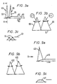
- FIG 3 a strip or plate (60) is shown being formed on a substrate (61) moving in the direction of arrow (62). But, in order to achieve maximum spray density whilst accommodating the maximum spray mass flux profile of a spray without defects consequential on too hot deposition (indicated by line (63) with respect to spray profiles (64), it is necessary to use two or more rows (65) of two or more atomized sprays (66) to produce strip with sufficiently uniform deposition conditions throughout the section even though the atomized sprays (66) scan transverse to the direction of movement as indicated by arrows (67).
- the spray cone generated by the atomizing device is always maintained, the tilting of the atomizer achieving to and fro movement of the spray cone, and the gas jets are used merely for atomization.
- the atomizing device may be tilted, but movement of the spray may be achieved without such motion.
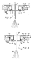
- a liquid stream (41) of molten metal or metal alloy is atomized by gas which is fed via pipes (42) to an atomiser body (43).
- the gas exits through orifices (44) arranged around the liquid stream (41) in a rotor (45) which is movable about the axis of the liquid stream (41) and may be arranged either to undertake angular oscillation to and fro about the stream or to undertake complete rotation about the stream.
- the size of the orifices (44) differ according to the circumferential position around the liquid stream in order to generate an asymmetric atomizing gas field.
- the rotor (45) is held in position by bearings (46) and (47), the gas leakage is prevented between the rotor (45) and the atomizer body (43) by suitable seals (48) and (49) as shown.
- the gas jets emerging from the orifices (44) atomize the liquid stream (41) to form the spray (50).
- the rotor (45) is movable about the stream (41) by means of a driven actuating means (51) such as a spur gear for example.
- a driven actuating means (51) such as a spur gear for example.
- figure 5 a similar apparatus is shown including a rotor (145) and similar reference numerals to those in figure 4 have been used in a one hundred series to indicate corresponding parts.
- the angles of attack of the emerging gas jets - indicated by references (152) - are varied about the circumference to produce the asymmetric spray pattern.
- combinations of figure 4 and figure 5 are possible, ie. varying the orifice size and the angles of attack.
- an asymmetric atomizing gas field is produced by means of two rotors which are rotatable relative to each other and to the atomizer body.
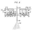
- a liquid metal stream (241) passing through the atomizer body is atomized by an atomizing gas fed via pipes (242) to the atomizer body (243).
- the gas is received in a plenum chamber (253) and exists the atomizer body (243) through atomizing orifices (244).
- the orifices (244) are arranged in two circular arrays in two concentric rotors (254, 255) and are distributed about the stream (241) in order to atomize it.
- each rotor (254, 255) differ according to their circumferential position around the liquid stream in order to generate an asymmetric atomizing gas field. However, by using two rotors (254, 255) more flexibility in the control of the resultant spray shape is provided.
- the inner rotor (254) is held in position by bearings (246) and (247) and the outer rotor (255) by bearings (256) and (257). Gas leakage is prevented between the rotors (254, 255) and the atomizer body (243) by suitable seals (248, 249 and 258).
- the arrays of gas jets in the respective rotors (254, 255) may be focused at a single atomizing point relative to the stream or at an atomizing zone (259) where the stream (241) is broken up into a spray.
- the rotors (254, 255) are movable by means of respective bevel gears (260, 261).
- the asymmetric gas flow field can be kept substantially constant and rotation or to and fro angular oscillation imparts movement to the spray whilst it retains its same cross-sectional shape determined by the gas flow field.
- by moving one rotor relative to the other the geometry of the gas flow field may be altered as well which provides increased flexibility.
- the atomizer with a rotor or rotors for rotation and/or angular to and fro oscillation about the stream can be used in the tilting arrangement of figure 1 so that the atomizing device tilts and rotates or angularly oscillates simultaneously.
- the additional rotation or angular oscillation of the atomizing rotor causes the locus of the spray axis indicated by lines (404) and (405) in figures 8a and 8b respectively to be spread (or to have an effective wider spray profile (407) as indicated in figure 8c with reference to the formation of tube) which allows the scanning speed of the spray to be reduced whilst still achieving the necessary overlap to give uniform deposition. As the scanning speed is reduced more metal can be put down without having a detrimental effect on the desired properties of the finished deposit.
- FIGS 9a and 9b the production of strip or plate (410) is diagrammatically illustrated.
- the addition of rotation or angular oscillation to the atomizing rotor produces a spread uniformity illustrated by spray profile (411) of figure 9c, such that only one row of tilting atomizers (412) is required as opposed to two greatly simplifying the plant needed and possibly increasing the production rate.
- spray profile (411) of figure 9c such that only one row of tilting atomizers (412) is required as opposed to two greatly simplifying the plant needed and possibly increasing the production rate.
- rows of two atomizers have been disclosed in figures 3a and 9a, if a reduced width of strip or plate is required then a single atomizer may be sufficient in the present invention as opposed to two atomizers, one behind the other, previously required.
- FIG. 10a shows a spray profile (420) achieve solely by tilting the atomizer to and fro
- figure 10b shows a spray profile (421) with the addition of rotation or angular oscillation to achieve greater spread.
- This results in more uniform deposition conditions throughout the thickness of the strip which will reduce the amount of porosity in the bottom and top surfaces of the strip deposit (caused by low deposition rates at the edge of the spray).
- the method of rotation of the present invention will also have significant advantages in the production of tubes, billets and clad products, particularly for billets and tubes of large diameter.
- the reason for this is that the spray will cover a larger area, ie. have a larger 'footprint' and therefore it is easier to obtain complete coverage of the tube or the billet surface compared to the old method solely of tilting.
- the invention has been particularly described with a stream axis which passes through the centre of a rotatable atomizing device, the axis of rotation of atomizer or the axis of the jets could be different to axis of metal stream. In this arrangement the holes could be uniform whilst the geometry of the gas flow field and thus the spray would be asymmetric to the liquid stream.
- the jets need not be arranged on a circle; for example, the jets could be in an elliptical arrangement and there could be one, two or more rotors. In the case of two rotors, these could be rotating in the same or opposite directions (or angularly oscillated in the same or opposite directions).
- the above devices can also be used for producing gas atomized metal powders whereby the movement of the spray can impart improved cooling to the atomised particles.
Landscapes
- Engineering & Computer Science (AREA)
- Mechanical Engineering (AREA)
- Manufacture And Refinement Of Metals (AREA)
- Nozzles (AREA)
- Manufacture Of Metal Powder And Suspensions Thereof (AREA)
Claims (19)
- Vorrichtung zur Gaszerstäubung eines Stroms geschmolzenen Metalls oder einer geschmolzenen Metallegierung- mit einer Zerstäubereinrichtung für die Aufnahme einer Zufuhr von Zerstäubungsgas,- mit einer Öffnung, die von der Zerstäubungseinrichtung gebildet wird und durch die der Strom gegossen werden kann,- mit einem Rotor, der von der Zerstäubungseinrichtung getragen wird und eine Ringdüse oder eine Vielzahl von Düsen aufweist, die um die Öffnung herum angeordnet sind, durch welche im Einsatz Zerstäubungsgas zur Zerstäubung des Stroms in einen Tröpfchensprühnebel austreten kann, wobei das aus der Ringdüse oder der Vielzahl von Düsen austretende Gas ein zerstäubendes Gasstromfeld bildet, das, wenn der Rotor stationär ist, den Strom umgeben und eine asymmetrische Geometrie bezüglich der Achse des Stroms haben würde, und- mit Einrichtungen zum Bewegen des Rotors relativ zur Zerstäubungseinrichtung, um die Lagebeziehung des asymmetrischen Gasstromfeldes bezüglich des Stroms zu verändern, wodurch die Asymmetrie des zerstäubenden Gasstromfeldes dem Sprühnebel bezüglich der Achse des Flüssigkeitsstroms eine Bewegung erteilen kann, während die Gesamtgeometrie des zerstäubenden Gasstromfelds im wesentlichen konstant bleibt.
- Vorrichtung nach Anspruch 1, bei welcher der zerstäubende Rotor eine Vielzahl von Zerstäubungsdüsen aufweist, deren Größe sich um den Rotor herum ändert, wodurch ein asymmetrisches Gasstromfeld erzeugt werden kann.
- Vorrichtung nach Anspruch 1, bei welcher eine Vielzahl von Zerstäuberdüsen vorhanden ist und das asymmetrische Gasstromfeld dadurch erzeugt wird, daß der Angriffswinkel an den Zerstäuberdüsen um den Rotor variiert wird.
- Vorrichtung nach Anspruch 1, bei welcher das asymmetrische Gasstromfeld dadurch erzeugt wird, daß die Achse des Rotors im Abstand von der Achse des Stroms angeordnet ist.
- Vorrichtung nach Anspruch 1, bei welcher eine Vielzahl von Zerstäuberdüsen vorgesehen sind und das asymmetrische Gasstromfeld dadurch erzeugt wird, daß die Zerstäubergasdüsen in dem Rotor asymmetrische bezüglich seiner Achse angeordnet sind.
- Vorrichtung nach Anspruch 1, bei welcher der zerstäubende Rotor eine Zerstäuberringdüse aufweist und das asymmetrische Gasstromfeld durch die Ringöffnung erzeugt wird, die eine Breite oder Lage in dem Rotor hat, die sich um den Rotor herum ändert, um das asymmetrische Gasstromfeld zu erzeugen.
- Vorrichtung nach Anspruch 1, bei welcher zwei Rotoren vorgesehen sind, von denen jeder eine Zerstäuberdüse oder Zerstäuberdüsen zur Bildung eines asymmetrischen Gasstromfelds bezüglich der Achse des Flüssigkeitsstroms hat und von denen jeder bezüglich des anderen und der Zerstäubereinrichtung bewegbar ist, wodurch in Kombination die Asymmetrie des Gasstromfelds bezüglich des Flüssigkeitsstroms variiert werden kann.
- Vorrichtung nach einem der vorhergehenden Ansprüche, welche weiterhin Einrichtungen zum Kippen der Zerstäubereinrichtung aufweist, so daß während der Zerstäubung der Sprühnebel durch Kippen der Zerstäubervorrichtung vor- und zurückbewegt werden kann.
- Vorrichtung nach Anspruch 1- mit einer in der Zerstäubervorrichtung ausgebildeten Hauptkammer,- mit einer mit der Zerstäubereinrichtung zum Tragen der Zerstäubereinrichtung gekoppelten Einrichtung, die einen Einlaßweg hat, der die Hauptkammer mit einer Zerstäubergasquelle in Verbindung setzt, und- mit einer Vielzahl von Zerstäubergasdüsenöffnungen, die in dem Rotor ausgebildet sind, um Zerstäubergas auf den Strom zu richten, der durch die Öffnung hindurchgeht, wobei die Zerstäubergasdüsenöffnungen in einer vorgegebenen, feststehenden Beziehung bezüglich einander positioniert sind, wodurch das asymmetrische Zerstäubergasstromfeld mit vorgegebener Geometrie gebildet wird.
- Vorrichtung nach Anspruch 9 mit einer Steuereinrichtung, die so arbeitet, daß dem Rotor entweder eine Winkeloszillationsbewegung oder eine vollständige Drehung erteilt wird.
- Vorrichtung nach Anspruch 10, bei welcher die Steuereinrichtung ein Stirnradgetriebe aufweist, das mit dem Rotor in Verbindung steht und so arbeitet, daß der Rotor bezüglich der Zerstäubereinrichtung bewegt wird.
- Vorrichtung nach Anspruch 1 mit wenigstens einem ersten und einem zweiten Rotor, die zueinander und zu der Zerstäubereinrichtung beweglich sind, wobei die Gesamtgeometrie des Zerstäubergasstromfelds im wesentlichen konstant bleibt, wenn die Rotoren synchronisiert sind.
- Verfahren zum Bewegen eines Sprühnebels aus zerstäubten Tröpfchen geschmolzenen Metalls oder einer geschmolzenen Metallegierung, das die Schritte aufweist,- einen Strom von geschmolzenem Metall oder geschmolzener Metallegierung durch eine Öffnung in einer Zerstäubereinrichtung hindurchzulassen,- die Zerstäubervorrichtung mit einem Rotor zu versehen, der eine Zerstäuberdüse oder Zerstäuberdüsen aufweist, die um die Öffnung herum angeordnet sind,- der Zerstäubereinrichtung Zerstäubergas zuzuführen, wodurch ein Zerstäubergasstromfeld gebildet wird, das, wenn der Rotor stationär ist, den Strom umgibt und bezüglich der Achse des Stroms eine asymmetrische Geometrie hat,- das Zerstäubergasstromfeld an den Strom so zu richten, daß der Strom in einen Sprühnebel von Tröpfchen zerstäubt wird, und- den Rotor so zu bewegen, daß die Lagebeziehung des Zerstäubergasstromfelds bezüglich des Stroms während des Zerstäubens verändert wird, um dem Sprühnebel eine Bewegung zu erteilen, während die Gesamtgeometrie des Zerstäubergasstromfelds im wesentlichen konstant gehalten wird.
- Verfahren nach Anspruch 13, zu welchem weiterhin das Kippen der Zerstäubereinrichtung um eine Achse gehört, um dem asymmetrischen Gasstromfeld eine Hin- und Herbewegung zu erteilen.
- Verfahren nach Anspruch 13, bei welchem der Sprühnebel gegen ein Substrat gerichtet wird, das sich kontinuierlich durch den Sprühnebel bewegt, wobei der Sprühnebel quer zur Bewegungsrichtung durch Hin- und Herkippen der Zerstäubereinrichtung bewegt wird, um eine gleichförmige Dicke der Abscheidung über dem Substrat zu erzielen, und der Sprühnebel seitlich in der Bewegungsrichtung auseinandergezogen wird, indem die Lagebeziehung des asymmetrischen Gasstromfelds verändert wird, um eine Gleichförmigkeit der Abscheidung in der Bewegungsrichtung des Substrats zu erzielen, um so Bandprodukte, beschichtete Bandprodukte, Plattenprodukte oder beschichtete Plattenprodukte herstellen zu können.
- Verfahren nach Anspruch 13, 14 oder 15, bei welchem in den Sprühnebel metallische oder keramische Teilchen aufgegeben werden, damit sie in einer auf einem Sammelsubstrat gebildeten Abscheidung eingeschlossen werden.
- Verfahren nach einem der Ansprüche 13 bis 16, bei welchem die Bewegungen des Sprühnebels so gesteuert werden, daß durch Sprühnebel abgeschiedene Barren, Stangen, Rohre, Ringe, Rollen, konische Formkörper, Schmiederohlinge und Extrusionsrohlinge, Formkörper für thixotrope Verformung, laminierte oder beschichtete Produkte und Metallmatrixverbundstoffe hergestellt werden.
- Verfahren nach Anspruch 13, bei welchem der Strom durch Aufbringen eines Zerstäubergases zerstäubt wird, das aus wenigstens zwei relativ drehbaren Rotoren austritt, und das den weiteren Schritt aufweist, die Lagebeziehung und/oder die Asymmetrie des Gasstromfelds bezüglich des Stroms während der Zerstäubung zu variieren, um dem Sprühnebel eine Bewegung zu erteilen, entweder dadurch, daß die Gesamtgeometrie des Zerstäubergasstromfelds im wesentlichen konstant gehalten wird, indem die Rotoren synchronisiert werden, oder dadurch, daß die Asymmetrie des Gasstromfelds variiert wird, indem eine Relativbewegung zwischen den Rotoren während der Zerstäubung bewirkt wird.
- Verfahren nach Anspruch 13, bei welchem der Sprühnebel im Flug abkühlen und sich verfestigen gelassen wird, wodurch Metallpulver gebildet wird.
Applications Claiming Priority (3)
| Application Number | Priority Date | Filing Date | Title |
|---|---|---|---|
| GB888824823A GB8824823D0 (en) | 1988-10-22 | 1988-10-22 | Atomisation of metals |
| GB8824823 | 1988-10-22 | ||
| PCT/GB1989/001248 WO1990004661A1 (en) | 1988-10-22 | 1989-10-20 | Atomization of metals |
Publications (2)
| Publication Number | Publication Date |
|---|---|
| EP0440706A1 EP0440706A1 (de) | 1991-08-14 |
| EP0440706B1 true EP0440706B1 (de) | 1995-08-02 |
Family
ID=10645672
Family Applications (1)
| Application Number | Title | Priority Date | Filing Date |
|---|---|---|---|
| EP89912118A Expired - Lifetime EP0440706B1 (de) | 1988-10-22 | 1989-10-20 | Atomisierung von metallen |
Country Status (7)
| Country | Link |
|---|---|
| EP (1) | EP0440706B1 (de) |
| JP (1) | JP2862927B2 (de) |
| AT (1) | ATE125882T1 (de) |
| AU (1) | AU637334B2 (de) |
| DE (1) | DE68923706T2 (de) |
| GB (1) | GB8824823D0 (de) |
| WO (1) | WO1990004661A1 (de) |
Families Citing this family (4)
| Publication number | Priority date | Publication date | Assignee | Title |
|---|---|---|---|---|
| GB9113304D0 (en) * | 1991-06-20 | 1991-08-07 | Alcan Int Ltd | Metal spraying apparatus |
| AU666456B3 (en) * | 1995-01-31 | 1996-02-08 | David Nathan | Nozzle assembly |
| JP2012000592A (ja) * | 2010-06-18 | 2012-01-05 | Kobe Steel Ltd | 高温溶湯のガスアトマイザー |
| RU2508964C1 (ru) * | 2012-11-26 | 2014-03-10 | Общество с ограниченной ответственностью "СУАЛ-ПМ" (ООО "СУАЛ-ПМ") | Способ распыления расплавленных металлов |
Family Cites Families (5)
| Publication number | Priority date | Publication date | Assignee | Title |
|---|---|---|---|---|
| US3725517A (en) * | 1971-11-26 | 1973-04-03 | Whittaker Corp | Powder production by gas atomization of liquid metal |
| US3911173A (en) * | 1973-02-05 | 1975-10-07 | Usm Corp | Adhesive process |
| GB8311167D0 (en) * | 1983-04-25 | 1983-06-02 | Jenkins W N | Directed spray |
| GB8527852D0 (en) * | 1985-11-12 | 1985-12-18 | Osprey Metals Ltd | Atomization of metals |
| DE3811077A1 (de) * | 1988-03-29 | 1989-10-19 | Mannesmann Ag | Einrichtung fuer die zerstaeubung eines giessstrahles fluessigen metalls |
-
1988
- 1988-10-22 GB GB888824823A patent/GB8824823D0/en active Pending
-
1989
- 1989-10-20 EP EP89912118A patent/EP0440706B1/de not_active Expired - Lifetime
- 1989-10-20 AT AT89912118T patent/ATE125882T1/de active
- 1989-10-20 JP JP1511183A patent/JP2862927B2/ja not_active Expired - Lifetime
- 1989-10-20 WO PCT/GB1989/001248 patent/WO1990004661A1/en not_active Ceased
- 1989-10-20 AU AU45061/89A patent/AU637334B2/en not_active Ceased
- 1989-10-20 DE DE68923706T patent/DE68923706T2/de not_active Expired - Fee Related
Also Published As
| Publication number | Publication date |
|---|---|
| JPH04501288A (ja) | 1992-03-05 |
| JP2862927B2 (ja) | 1999-03-03 |
| AU637334B2 (en) | 1993-05-27 |
| DE68923706D1 (de) | 1995-09-07 |
| GB8824823D0 (en) | 1988-11-30 |
| AU4506189A (en) | 1990-05-14 |
| DE68923706T2 (de) | 1996-01-18 |
| EP0440706A1 (de) | 1991-08-14 |
| ATE125882T1 (de) | 1995-08-15 |
| WO1990004661A1 (en) | 1990-05-03 |
Similar Documents
| Publication | Publication Date | Title |
|---|---|---|
| US4779802A (en) | Atomization of metals | |
| EP0225732B1 (de) | Herstellen von Schichten durch Zerstäuben von flüssigen Metallen | |
| US4905899A (en) | Atomisation of metals | |
| EP0244454B1 (de) | Herstellen von schichten durch zerstäuben von flüssigen metallen | |
| US4064295A (en) | Spraying atomized particles | |
| EP0659898B1 (de) | Düse zum Zerstäuben flüssiger Metalle | |
| US5460851A (en) | Spray deposition of metals | |
| US5954112A (en) | Manufacturing of large diameter spray formed components using supplemental heating | |
| US5401539A (en) | Production of metal spray deposits | |
| AU637334B2 (en) | Atomization of metals | |
| US4977950A (en) | Ejection nozzle for imposing high angular momentum on molten metal stream for producing particle spray | |
| US4901784A (en) | Gas atomizer for spray casting | |
| EP0852976B1 (de) | Verfahren und Anlage zum Aufsprühen | |
| US5634593A (en) | Apparatus for scanning a stream of atomized particles having externally adjustable and programmable gas routing | |
| CA2040968A1 (en) | Oscillating spray apparatus | |
| US6093449A (en) | Atomizer for spray forming ring structures | |
| KR100360379B1 (ko) | 광폭합금판재제조용분무주조장치 | |
| CA1268313A (en) | Atomisation of metals | |
| CA1263062A (en) | Production of spray deposits | |
| KR20000042172A (ko) | 다층 복합판재 제조용 분무주조장치 | |
| KR200169960Y1 (ko) | 가스분무 주조장치 | |
| KR20010057616A (ko) | 광폭 롤 제조용 다중 노즐 가스분무 주조장치 | |
| KR100590810B1 (ko) | 고속 주조용 다중분무성형장치 | |
| WO1990010514A1 (en) | Atomizing devices and methods for spray casting | |
| RU1770097C (ru) | Распыливающее устройство установки дл получени порошка |
Legal Events
| Date | Code | Title | Description |
|---|---|---|---|
| PUAI | Public reference made under article 153(3) epc to a published international application that has entered the european phase |
Free format text: ORIGINAL CODE: 0009012 |
|
| 17P | Request for examination filed |
Effective date: 19910410 |
|
| AK | Designated contracting states |
Kind code of ref document: A1 Designated state(s): AT BE CH DE FR GB IT LI LU NL SE |
|
| 17Q | First examination report despatched |
Effective date: 19920623 |
|
| GRAA | (expected) grant |
Free format text: ORIGINAL CODE: 0009210 |
|
| AK | Designated contracting states |
Kind code of ref document: B1 Designated state(s): AT BE CH DE FR GB IT LI LU NL SE |
|
| PG25 | Lapsed in a contracting state [announced via postgrant information from national office to epo] |
Ref country code: IT Free format text: LAPSE BECAUSE OF FAILURE TO SUBMIT A TRANSLATION OF THE DESCRIPTION OR TO PAY THE FEE WITHIN THE PRE;WARNING: LAPSES OF ITALIAN PATENTS WITH EFFECTIVE DATE BEFORE 2007 MAY HAVE OCCURRED AT ANY TIME BEFORE 2007. THE CORRECT EFFECTIVE DATE MAY BE DIFFERENT FROM THE ONE RECORDED.SCRIBED TIME-LIMIT Effective date: 19950802 Ref country code: NL Free format text: LAPSE BECAUSE OF NON-PAYMENT OF DUE FEES Effective date: 19950802 Ref country code: AT Effective date: 19950802 |
|
| REF | Corresponds to: |
Ref document number: 125882 Country of ref document: AT Date of ref document: 19950815 Kind code of ref document: T |
|
| ET | Fr: translation filed | ||
| REF | Corresponds to: |
Ref document number: 68923706 Country of ref document: DE Date of ref document: 19950907 |
|
| PG25 | Lapsed in a contracting state [announced via postgrant information from national office to epo] |
Ref country code: LU Free format text: LAPSE BECAUSE OF NON-PAYMENT OF DUE FEES Effective date: 19951031 |
|
| PGFP | Annual fee paid to national office [announced via postgrant information from national office to epo] |
Ref country code: CH Payment date: 19951031 Year of fee payment: 7 |
|
| PG25 | Lapsed in a contracting state [announced via postgrant information from national office to epo] |
Ref country code: SE Effective date: 19951102 |
|
| NLV1 | Nl: lapsed or annulled due to failure to fulfill the requirements of art. 29p and 29m of the patents act | ||
| PLBE | No opposition filed within time limit |
Free format text: ORIGINAL CODE: 0009261 |
|
| STAA | Information on the status of an ep patent application or granted ep patent |
Free format text: STATUS: NO OPPOSITION FILED WITHIN TIME LIMIT |
|
| 26N | No opposition filed | ||
| PG25 | Lapsed in a contracting state [announced via postgrant information from national office to epo] |
Ref country code: LI Free format text: LAPSE BECAUSE OF FAILURE TO SUBMIT A TRANSLATION OF THE DESCRIPTION OR TO PAY THE FEE WITHIN THE PRESCRIBED TIME-LIMIT Effective date: 19961031 Ref country code: CH Free format text: LAPSE BECAUSE OF FAILURE TO SUBMIT A TRANSLATION OF THE DESCRIPTION OR TO PAY THE FEE WITHIN THE PRESCRIBED TIME-LIMIT Effective date: 19961031 |
|
| PGFP | Annual fee paid to national office [announced via postgrant information from national office to epo] |
Ref country code: BE Payment date: 20010926 Year of fee payment: 13 |
|
| PGFP | Annual fee paid to national office [announced via postgrant information from national office to epo] |
Ref country code: DE Payment date: 20011227 Year of fee payment: 13 |
|
| REG | Reference to a national code |
Ref country code: GB Ref legal event code: IF02 |
|
| PGFP | Annual fee paid to national office [announced via postgrant information from national office to epo] |
Ref country code: GB Payment date: 20020920 Year of fee payment: 14 |
|
| PGFP | Annual fee paid to national office [announced via postgrant information from national office to epo] |
Ref country code: FR Payment date: 20020930 Year of fee payment: 14 |
|
| PG25 | Lapsed in a contracting state [announced via postgrant information from national office to epo] |
Ref country code: BE Free format text: LAPSE BECAUSE OF NON-PAYMENT OF DUE FEES Effective date: 20021031 |
|
| BERE | Be: lapsed |
Owner name: *OSPREY METALS LTD Effective date: 20021031 |
|
| PG25 | Lapsed in a contracting state [announced via postgrant information from national office to epo] |
Ref country code: DE Free format text: LAPSE BECAUSE OF NON-PAYMENT OF DUE FEES Effective date: 20030501 |
|
| PG25 | Lapsed in a contracting state [announced via postgrant information from national office to epo] |
Ref country code: GB Free format text: LAPSE BECAUSE OF NON-PAYMENT OF DUE FEES Effective date: 20031020 |
|
| GBPC | Gb: european patent ceased through non-payment of renewal fee |
Effective date: 20031020 |
|
| PG25 | Lapsed in a contracting state [announced via postgrant information from national office to epo] |
Ref country code: FR Free format text: LAPSE BECAUSE OF NON-PAYMENT OF DUE FEES Effective date: 20040630 |
|
| REG | Reference to a national code |
Ref country code: FR Ref legal event code: ST |