EP0440832A1 - Table de mesure des angles - Google Patents
Table de mesure des angles Download PDFInfo
- Publication number
- EP0440832A1 EP0440832A1 EP90102204A EP90102204A EP0440832A1 EP 0440832 A1 EP0440832 A1 EP 0440832A1 EP 90102204 A EP90102204 A EP 90102204A EP 90102204 A EP90102204 A EP 90102204A EP 0440832 A1 EP0440832 A1 EP 0440832A1
- Authority
- EP
- European Patent Office
- Prior art keywords
- stator
- angular
- angle measuring
- angle
- rotary table
- Prior art date
- Legal status (The legal status is an assumption and is not a legal conclusion. Google has not performed a legal analysis and makes no representation as to the accuracy of the status listed.)
- Granted
Links
- 238000005259 measurement Methods 0.000 claims abstract description 19
- 238000012360 testing method Methods 0.000 description 6
- 238000000034 method Methods 0.000 description 5
- 238000010998 test method Methods 0.000 description 2
- 238000012935 Averaging Methods 0.000 description 1
- 241001598984 Bromius obscurus Species 0.000 description 1
- 238000012937 correction Methods 0.000 description 1
- 238000001514 detection method Methods 0.000 description 1
- 238000011161 development Methods 0.000 description 1
- 230000018109 developmental process Effects 0.000 description 1
- 230000007613 environmental effect Effects 0.000 description 1
- 238000009434 installation Methods 0.000 description 1
- 238000004519 manufacturing process Methods 0.000 description 1
Images
Classifications
-
- G—PHYSICS
- G01—MEASURING; TESTING
- G01B—MEASURING LENGTH, THICKNESS OR SIMILAR LINEAR DIMENSIONS; MEASURING ANGLES; MEASURING AREAS; MEASURING IRREGULARITIES OF SURFACES OR CONTOURS
- G01B5/00—Measuring arrangements characterised by the use of mechanical techniques
- G01B5/0002—Arrangements for supporting, fixing or guiding the measuring instrument or the object to be measured
- G01B5/0004—Supports
-
- G—PHYSICS
- G01—MEASURING; TESTING
- G01D—MEASURING NOT SPECIALLY ADAPTED FOR A SPECIFIC VARIABLE; ARRANGEMENTS FOR MEASURING TWO OR MORE VARIABLES NOT COVERED IN A SINGLE OTHER SUBCLASS; TARIFF METERING APPARATUS; MEASURING OR TESTING NOT OTHERWISE PROVIDED FOR
- G01D5/00—Mechanical means for transferring the output of a sensing member; Means for converting the output of a sensing member to another variable where the form or nature of the sensing member does not constrain the means for converting; Transducers not specially adapted for a specific variable
- G01D5/26—Mechanical means for transferring the output of a sensing member; Means for converting the output of a sensing member to another variable where the form or nature of the sensing member does not constrain the means for converting; Transducers not specially adapted for a specific variable characterised by optical transfer means, i.e. using infrared, visible, or ultraviolet light
- G01D5/32—Mechanical means for transferring the output of a sensing member; Means for converting the output of a sensing member to another variable where the form or nature of the sensing member does not constrain the means for converting; Transducers not specially adapted for a specific variable characterised by optical transfer means, i.e. using infrared, visible, or ultraviolet light with attenuation or whole or partial obturation of beams of light
- G01D5/34—Mechanical means for transferring the output of a sensing member; Means for converting the output of a sensing member to another variable where the form or nature of the sensing member does not constrain the means for converting; Transducers not specially adapted for a specific variable characterised by optical transfer means, i.e. using infrared, visible, or ultraviolet light with attenuation or whole or partial obturation of beams of light the beams of light being detected by photocells
- G01D5/347—Mechanical means for transferring the output of a sensing member; Means for converting the output of a sensing member to another variable where the form or nature of the sensing member does not constrain the means for converting; Transducers not specially adapted for a specific variable characterised by optical transfer means, i.e. using infrared, visible, or ultraviolet light with attenuation or whole or partial obturation of beams of light the beams of light being detected by photocells using displacement encoding scales
- G01D5/3473—Circular or rotary encoders
Definitions
- the invention relates to an angle measuring table according to the preamble of claim 1.
- the invention has for its object to provide an angle measuring table of the type mentioned, which enables the detection of a temporally changing error profile of the angular division when the object is applied to the rotary table.
- the advantages achieved by the invention consist in particular in that, by integrating the calibration device in the angle measuring table, the calibration of the first angular division can be carried out as often as desired, in particular before an angle measuring process or angle setting process, the surface of the rotary table being available for measuring structures during the calibration process.
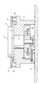
- a cross-section shows an angle measuring table with a rotary table 1, the rotor 2 of which is mounted in a stator 5 by means of an axial air bearing 3 and by means of a radial air bearing 4; the stator 5 is fixed on a base plate 6.
- the angle measuring table is used for angle measurement or angle adjustment of an object, not shown, which is applied to the flat surface 7 of the rotary table 1.
- a first partial disk 9 with a first angular division is attached concentrically to the rotary table 1 and is scanned by two diametrically opposed first scanning units 10 for determining angular measurement values for the angular position of the test object with respect to a zero position; the two first scanning units 10 are fastened diametrically opposite one another on the stator 5 and, together with the first partial disk 9, form a first angle measuring device.
- the first angular division of the first graduated disk 9 generally has certain errors which can lead to unsustainable angle measurement errors in precision measurements.
- a calibration device in the form of a second angular measuring device is integrated in the angle measuring table below the radial air bearing 4, which has a second graduated disk 11 with a second angular graduation and two second scanning units 12, which are diametrically opposite one another Stator 5 are attached.
- the second partial disk 11 is rotatably arranged concentrically on the rotor 2 by means of a slip clutch 13 which is acted upon by a plate spring 14 supported on the rotor 2.
- a locking lever 15 pivotably mounted in the stator 5 and a cam 16 of the slip clutch 13, the second partial disk 11 can be locked in the zero position on the stator 5 in a rotationally fixed manner.
- the locking lever 15 can be actuated electromechanically or pneumatically.
- the first partial disk 9 is measured by means of a rotor drive (not shown) for the rotary table 1 in a first series of measurements in n angular positions with a respective mutual offset of 360 ° / n with respect to the rotating second partial disk 11.
- the second indexing disk 11 is connected to the stator 5 in a torsionally rigid manner by means of the locking lever 15 and the cam 16 of the slip clutch 13, and the first angular division is further rotated by an angle of 360 ° / n relative to the second angular division by means of the rotor drive of the rotary table 1.
- the first partial disk 9 together with the second partial disk 11 are again measured in n angular positions with the respective mutual offset of 360 ° / n for the second series of measurements.
- This calibration process is continued until there are n series of measurements, so that n2 measured values are available.
- the errors of the first angular division and the errors of the second angular division can be separated from one another and the corresponding error correction values for correcting the angle measured values can be determined therefrom.
- the flat surface 7 of the turntable 1 is available for measurement setups during the calibration process.
- the test object can therefore be arranged on the flat surface 7 of the rotary table 1 and a test measurement of the angular position of the test object can first be carried out. After the subsequent calibration of the first angular division, the measurement of the angular position of the test object can be carried out again.
- the invention can also be used with success in partial machine tables and in any partial, measuring or angle setting devices.
Landscapes
- Physics & Mathematics (AREA)
- General Physics & Mathematics (AREA)
- Length Measuring Devices With Unspecified Measuring Means (AREA)
Priority Applications (4)
| Application Number | Priority Date | Filing Date | Title |
|---|---|---|---|
| EP19900102204 EP0440832B1 (fr) | 1990-02-05 | 1990-02-05 | Table de mesure des angles |
| DE9090102204T DE59001704D1 (de) | 1990-02-05 | 1990-02-05 | Winkelmesstisch. |
| DE9007815U DE9007815U1 (de) | 1990-02-05 | 1990-03-24 | Winkelmeßtisch |
| DE19904009577 DE4009577A1 (de) | 1990-02-05 | 1990-03-24 | Winkelmesstisch |
Applications Claiming Priority (1)
| Application Number | Priority Date | Filing Date | Title |
|---|---|---|---|
| EP19900102204 EP0440832B1 (fr) | 1990-02-05 | 1990-02-05 | Table de mesure des angles |
Publications (2)
| Publication Number | Publication Date |
|---|---|
| EP0440832A1 true EP0440832A1 (fr) | 1991-08-14 |
| EP0440832B1 EP0440832B1 (fr) | 1993-06-09 |
Family
ID=8203587
Family Applications (1)
| Application Number | Title | Priority Date | Filing Date |
|---|---|---|---|
| EP19900102204 Expired - Lifetime EP0440832B1 (fr) | 1990-02-05 | 1990-02-05 | Table de mesure des angles |
Country Status (2)
| Country | Link |
|---|---|
| EP (1) | EP0440832B1 (fr) |
| DE (2) | DE59001704D1 (fr) |
Cited By (4)
| Publication number | Priority date | Publication date | Assignee | Title |
|---|---|---|---|---|
| GB2291193A (en) * | 1994-07-07 | 1996-01-17 | Eastman Machine Co | Co-ordinate measuring machine |
| CN100451534C (zh) * | 2004-09-29 | 2009-01-14 | 约翰尼斯海登海恩博士股份有限公司 | 对于具有角标度的物体进行制造和安装的方法 |
| CN102673997A (zh) * | 2012-05-17 | 2012-09-19 | 苏州美罗升降机械有限公司 | 旋转圆台 |
| CN105783847A (zh) * | 2014-12-23 | 2016-07-20 | 丹东华通测控有限公司 | 一种角位移传感器校准装置 |
Families Citing this family (1)
| Publication number | Priority date | Publication date | Assignee | Title |
|---|---|---|---|---|
| US6964102B2 (en) | 2000-09-18 | 2005-11-15 | Dr. Johannes Heidenhain Gmbh | Device and method for detecting the rotational movement of an element rotatably mounted about an axis |
Citations (1)
| Publication number | Priority date | Publication date | Assignee | Title |
|---|---|---|---|---|
| EP0157239A2 (fr) * | 1984-03-31 | 1985-10-09 | Dr. Johannes Heidenhain GmbH | Dispositif de mesure de position |
-
1990
- 1990-02-05 DE DE9090102204T patent/DE59001704D1/de not_active Expired - Fee Related
- 1990-02-05 EP EP19900102204 patent/EP0440832B1/fr not_active Expired - Lifetime
- 1990-03-24 DE DE19904009577 patent/DE4009577A1/de not_active Withdrawn
Patent Citations (1)
| Publication number | Priority date | Publication date | Assignee | Title |
|---|---|---|---|---|
| EP0157239A2 (fr) * | 1984-03-31 | 1985-10-09 | Dr. Johannes Heidenhain GmbH | Dispositif de mesure de position |
Non-Patent Citations (2)
| Title |
|---|
| PATENT ABSTRACTS OF JAPAN, Band 11, Nr. 98 (M-575), 27. März 1987; & JP-A-61 247 543 (TAKEO ISAKA) 04-11-1986 * |
| PATENT ABSTRACTS OF JAPAN, Band 9, Nr. 161 (P-370), 5. Juli 1985; & JP-A-60 037 544 (KONISHIROKU SHASHIN KOGYO K.K.) 26-02-1985 * |
Cited By (6)
| Publication number | Priority date | Publication date | Assignee | Title |
|---|---|---|---|---|
| GB2291193A (en) * | 1994-07-07 | 1996-01-17 | Eastman Machine Co | Co-ordinate measuring machine |
| GB2291193B (en) * | 1994-07-07 | 1997-12-03 | Eastman Machine Co | Co-ordinate measuring machine |
| CN100451534C (zh) * | 2004-09-29 | 2009-01-14 | 约翰尼斯海登海恩博士股份有限公司 | 对于具有角标度的物体进行制造和安装的方法 |
| CN102673997A (zh) * | 2012-05-17 | 2012-09-19 | 苏州美罗升降机械有限公司 | 旋转圆台 |
| CN105783847A (zh) * | 2014-12-23 | 2016-07-20 | 丹东华通测控有限公司 | 一种角位移传感器校准装置 |
| CN105783847B (zh) * | 2014-12-23 | 2018-10-23 | 丹东华通测控有限公司 | 一种角位移传感器校准装置 |
Also Published As
| Publication number | Publication date |
|---|---|
| DE4009577A1 (de) | 1991-08-08 |
| EP0440832B1 (fr) | 1993-06-09 |
| DE59001704D1 (de) | 1993-07-15 |
Similar Documents
| Publication | Publication Date | Title |
|---|---|---|
| EP0931241B1 (fr) | Procede de correction des erreurs de mesure d'une machine de mesure par coordonnees | |
| DE69625001T2 (de) | Kalibrierung eines Gelenktastkopfs für eine Koordinaten-Positionsmaschine | |
| DE2537328C2 (de) | Meßeinrichtung und Verfahren zum Bestimmen des Krümmungsradius der gekrümmten Fläche eines Prüflings oder des Abstandes zwischen zwei Flächen | |
| DE60132073T3 (de) | Vorrichtung und verfahren zum messen der dimensions- und formabweichung von kurbelzapfen am ort des schleifens | |
| DE2824121C2 (de) | Dehnungsmeßvorrichtung | |
| EP0068082B1 (fr) | Procédé pour la mesure des déviations de la rondeur de corps rotation-symétriques | |
| DE112006003663B4 (de) | Drehkodierer | |
| EP1923670B1 (fr) | Dispositif de mesure de position | |
| DE10020978A1 (de) | Drehcodierer insbesondere für ein Vermessungsinstrument | |
| DE10128619B4 (de) | Magnetischer Inkrementalcodierer und Vermessungsinstrument mit einem magnetischen Inkrementalcodierer | |
| EP0325924B1 (fr) | Standard circulaire | |
| DE2820753B1 (de) | Einrichtung zur Fehlerkorrektur bei Positionsmesssystemen | |
| DE3616177C2 (fr) | ||
| EP0440832B1 (fr) | Table de mesure des angles | |
| EP0395936B1 (fr) | Dispositif de mesure de position avec plusieurs points de capteur | |
| EP1632754A1 (fr) | Méthode et dispositif pour la détermination précise d'un angle de rotation | |
| DE3901546A1 (de) | Positionsmesseinrichtung mit mehreren abtaststellen | |
| DE4402401C2 (de) | Winkelmeßeinrichtung mit mehreren Abtaststellen | |
| DE3210962C2 (fr) | ||
| DE9007815U1 (de) | Winkelmeßtisch | |
| DE4009593A1 (de) | Winkelmesseinrichtung | |
| EP3760981A1 (fr) | Dispositif de mesure d'angle et procédé de fonctionnement d'un dispositif de mesure d'angle | |
| DE2329712A1 (de) | Anordnung zum kompensation von laengenaenderungen | |
| DE2711965C2 (fr) | ||
| DE102017128395A1 (de) | Drehwinkelsensoreinheit und Verfahren zum Bestimmen eines Drehwinkels |
Legal Events
| Date | Code | Title | Description |
|---|---|---|---|
| PUAI | Public reference made under article 153(3) epc to a published international application that has entered the european phase |
Free format text: ORIGINAL CODE: 0009012 |
|
| 17P | Request for examination filed |
Effective date: 19900215 |
|
| AK | Designated contracting states |
Kind code of ref document: A1 Designated state(s): DE FR GB IT |
|
| 17Q | First examination report despatched |
Effective date: 19921109 |
|
| GRAA | (expected) grant |
Free format text: ORIGINAL CODE: 0009210 |
|
| ITF | It: translation for a ep patent filed | ||
| AK | Designated contracting states |
Kind code of ref document: B1 Designated state(s): DE FR GB IT |
|
| REF | Corresponds to: |
Ref document number: 59001704 Country of ref document: DE Date of ref document: 19930715 |
|
| GBT | Gb: translation of ep patent filed (gb section 77(6)(a)/1977) |
Effective date: 19930622 |
|
| ET | Fr: translation filed | ||
| PLBE | No opposition filed within time limit |
Free format text: ORIGINAL CODE: 0009261 |
|
| STAA | Information on the status of an ep patent application or granted ep patent |
Free format text: STATUS: NO OPPOSITION FILED WITHIN TIME LIMIT |
|
| 26N | No opposition filed | ||
| REG | Reference to a national code |
Ref country code: GB Ref legal event code: IF02 |
|
| PGFP | Annual fee paid to national office [announced via postgrant information from national office to epo] |
Ref country code: GB Payment date: 20020115 Year of fee payment: 13 |
|
| PGFP | Annual fee paid to national office [announced via postgrant information from national office to epo] |
Ref country code: FR Payment date: 20020207 Year of fee payment: 13 |
|
| PG25 | Lapsed in a contracting state [announced via postgrant information from national office to epo] |
Ref country code: GB Free format text: LAPSE BECAUSE OF NON-PAYMENT OF DUE FEES Effective date: 20030205 |
|
| GBPC | Gb: european patent ceased through non-payment of renewal fee | ||
| PG25 | Lapsed in a contracting state [announced via postgrant information from national office to epo] |
Ref country code: FR Free format text: LAPSE BECAUSE OF NON-PAYMENT OF DUE FEES Effective date: 20031031 |
|
| REG | Reference to a national code |
Ref country code: FR Ref legal event code: ST |
|
| PG25 | Lapsed in a contracting state [announced via postgrant information from national office to epo] |
Ref country code: IT Free format text: LAPSE BECAUSE OF NON-PAYMENT OF DUE FEES;WARNING: LAPSES OF ITALIAN PATENTS WITH EFFECTIVE DATE BEFORE 2007 MAY HAVE OCCURRED AT ANY TIME BEFORE 2007. THE CORRECT EFFECTIVE DATE MAY BE DIFFERENT FROM THE ONE RECORDED. Effective date: 20050205 |
|
| PGFP | Annual fee paid to national office [announced via postgrant information from national office to epo] |
Ref country code: DE Payment date: 20050208 Year of fee payment: 16 |
|
| PG25 | Lapsed in a contracting state [announced via postgrant information from national office to epo] |
Ref country code: DE Free format text: LAPSE BECAUSE OF NON-PAYMENT OF DUE FEES Effective date: 20060901 |