EP0440900A2 - Fernbedienbares Spielzeug - Google Patents
Fernbedienbares Spielzeug Download PDFInfo
- Publication number
- EP0440900A2 EP0440900A2 EP90122667A EP90122667A EP0440900A2 EP 0440900 A2 EP0440900 A2 EP 0440900A2 EP 90122667 A EP90122667 A EP 90122667A EP 90122667 A EP90122667 A EP 90122667A EP 0440900 A2 EP0440900 A2 EP 0440900A2
- Authority
- EP
- European Patent Office
- Prior art keywords
- transmitter
- model vehicle
- resonator
- remotely
- secondary battery
- Prior art date
- Legal status (The legal status is an assumption and is not a legal conclusion. Google has not performed a legal analysis and makes no representation as to the accuracy of the status listed.)
- Withdrawn
Links
- 239000013078 crystal Substances 0.000 description 3
- 238000000034 method Methods 0.000 description 3
- 230000007935 neutral effect Effects 0.000 description 3
- OJIJEKBXJYRIBZ-UHFFFAOYSA-N cadmium nickel Chemical compound [Ni].[Cd] OJIJEKBXJYRIBZ-UHFFFAOYSA-N 0.000 description 2
- 230000010355 oscillation Effects 0.000 description 2
- 238000010276 construction Methods 0.000 description 1
- 230000000694 effects Effects 0.000 description 1
- 238000003780 insertion Methods 0.000 description 1
- 230000037431 insertion Effects 0.000 description 1
- 238000005476 soldering Methods 0.000 description 1
Images


Classifications
-
- A—HUMAN NECESSITIES
- A63—SPORTS; GAMES; AMUSEMENTS
- A63H—TOYS, e.g. TOPS, DOLLS, HOOPS OR BUILDING BLOCKS
- A63H29/00—Drive mechanisms for toys in general
- A63H29/22—Electric drives
-
- A—HUMAN NECESSITIES
- A63—SPORTS; GAMES; AMUSEMENTS
- A63H—TOYS, e.g. TOPS, DOLLS, HOOPS OR BUILDING BLOCKS
- A63H29/00—Drive mechanisms for toys in general
- A63H29/24—Details or accessories for drive mechanisms, e.g. means for winding-up or starting toy engines
-
- A—HUMAN NECESSITIES
- A63—SPORTS; GAMES; AMUSEMENTS
- A63H—TOYS, e.g. TOPS, DOLLS, HOOPS OR BUILDING BLOCKS
- A63H30/00—Remote-control arrangements specially adapted for toys, e.g. for toy vehicles
- A63H30/02—Electrical arrangements
- A63H30/04—Electrical arrangements using wireless transmission
Definitions
- This invention relates to a remotely-controlled toy constituted by a set of transmitter/receiver that comprises a transmitter which generates a specific set of remote control signals and a model vehicle which is controlled by the specific set of remote control signals generated by the transmitter. More specifically, this invention relates to a remotely-controlled toy wherein the said transmitter is equipped with a device for recharging the secondary battery incorporated in the model vehicle, thereby facilitating recharging of the secondary battery in the site where the model vehicle is run.
- This invention also relates to a remotely-controlled toy wherein an resonator mounted in the said model vehicle is so constructed as to be accessible and replaceable by hand, thus facilitating replacement of the resonator in the site where the model vehicle is run without having to use tools or to disassemble any part of the model vehicle.
- a certain sort of remotely-controlled toy constituted by a set of transmitter/receiver which comprises a transmitter that generates a specific set of remote control signals and a model vehicle controlled by the specific set of remote control signals is already known to the public.
- This sort of remotely-controlled toy is used in such manner that a number of transmitters which generate a different specific set of remote control signals and an equal number of model vehicles forming a counterpart to these transmitters are gathered up and each of the model vehicles is individually controlled by its counterpart transmitter.
- An example of such applications is a game in which these toys are run on a particular racing course and compete with each other in running time.
- This conventional sort of model vehicle has a built-in rechargeable secondary battery to drive itself.
- this secondary battery consumes its charged electric energy with the running time of the model vehicle in which it is incorporated and that it eventually loses its function as battery.
- the conventional sort of recharging device is powered by commercial power supply and is separately encased from the transmitter.
- Such a recharging device therefore, cannot be used to recharge remotely-controlled model vehicles in the site of the run, and outdoor running of such model vehicles requires players either to have their model vehicle recharged indoors prior to the run or to bring with them a certain number of recharged spare batteries to the site of the run.
- each of the counterpart transmitters in order to allow a number of players to run their own model vehicle at almost the same time and on an individual basis, each of the counterpart transmitters must generate a different specific set of remote control signals at almost the same time and each of receivers must receive the signal generated by its counterpart transmitter at almost the same time.
- the resonator is, however, mounted on connectors supported in the printed circuit board in such manner that it can be only removed or mounted from above the printed circuit board fitted on the upper side of the chassis of the model vehicle.
- the present invention in order to overcome the former disadvantage of the conventional sort of remote-controlled toys, includes a device for recharging the model vehicle's built-in secondary battery in a transmitter with which the model vehicle is controlled, thus facilitating recharging operation in the site of the model vehicle is run.
- the present invention has the chassis of the model vehicle perforated with a through hole for replacing the resonator, thus allowing the resonator to be replaced directly by hand without having to remove the case cover.
- This invention represents a remotely-controlled toy comprising a transmitter which generates a specific set of remote control signals and a model vehicle controlled by the specific set of remote control signals generated by the transmitter, wherein the model vehicle has a built-in secondary battery and the said transmitter is equipped with a device for recharging the secondary battery. This facilitates recharging of the model vehicle's secondary battery in the site where the model vehicle is run.
- the present invention represents a remotely-controlled toy comprising a transmitter which generates a specific set of remote control signals and a model vehicle controlled by the specific set of remote control signals generated by the transmitter, wherein the chassis of the mode is perforated with a through hole for replacing an resonator. This allows the resonator to be replaced easily and quickly by hand without having to use tools.
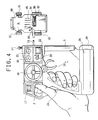
- a transmitter T
- (1) is a case assembly with the front and back case components jointed;
- (2) is a charging lever which is positioned in the upper back part of the case assembly (1) in such manner that it can slide back and forth;
- (3) is guide members which protrude, as shown in Fig.
- each of the guide members has an engaging section at its protruding end, opposing to each other;
- (5) is a slider, the front end (6) of which is held between the said guide members (3) in such manner that it can slide back and forth, and the back end (7) of which is fixed to the charging lever (2) by means of, for example, a screw;
- (9) is a spring, an end of which is fitted to a protrusion (10) at the back end (7) of the slider (5), with the other end of which being fitted to a protrusion (11) on the inside surface of the front case component;
- (12) is, for example, a known charging plug assembly, which is fixed at the front end (6) of the slider (5).
- a fitting hole (14) is made at the front end (6) of the slider to fit in the plug (13) of the charging plug assembly (12), and members (16) are provided to hold the circumference of the charging plug assembly (12) firmly in position vertically.
- the plug (13) of the charging plug assembly (12) is inserted in the fitting hole (14), and with the plug protruded from the front end (6) of the slider (5), the plug assembly (12) is firmly held in its vertical and transverse position by the holding members (16), and thus the charging plug assembly (12) is fixed at the front end (6) of the slider (5).
- (17) is, for example, a cap of a crystal resonator (hereinafter referred to as resonator), wherein a resonator is contained in such manner that it can be replaced.
- (18) is a known steering wheel that controls a known steering mechanism of a model car (R) in the present embodiment which will be described later.
- the steering wheel (18) is supported in the upper central part of the case assembly (1) in such manner that it can rotate therein. Steering, for example, of front wheels of the model car (R) to the right or left is implemented by rotating the steering wheel (18) to the right or left.
- (19) is a known throttle trigger which is borne in a lower part of the case assembly that corresponds to the steering wheel (18) in such manner that it can rotate in the direction of the arrows A and B, and which throttle trigger is elastically held by a spring so that it returns to the neutral position after it is actuated.
- (20) is a known steering trim which is placed in the upper front section of the case assembly (1) in such manner that it can rotate both clockwise and counterclockwise. The steering trim (20) fine- adjusts the neutral position of the steering mechanism of the car (R) that will be described later.
- (21) is a known throttle trim which is placed in the upper front part of the case assembly (1) in such manner that it can rotate both clockwise and counterclockwise.
- the throttle trim (21) fine-adjusts the neutral position of the throttle trigger.
- (22) is a switch for selecting operating mode of the transmitter.
- the switch (22) is placed in the upper front part of the case assembly (1), and chooses among three positions; OFF; Charge (CH); and ON.
- (23) is a pilot lamp which is fitted near the switch (22) in the case assembly (1) and which pilot lamp (23) turns on when the switch (22) is in the ON position, turns off when the switch (22) is in the OFF position, and turns on and off when the switch (22) is in the CH position.
- the pilot lamp (23) also turns on and off when the capacity of battery, which will be described later, lowers below a specified level.
- (24) is a grip provided in the middle back part of the case assembly (1).
- (25) is a section to accommodate batteries which is provided in the bottom of the case assembly (1) and which section (24) is provided with a hatch (26).
- (27) is a known rod-type antenna.
- Figs. 3 and 5 (30) is a chassis of the car (R). (31) and (32) are front and rear wheels, respectively. (33) is a main switch of the model car (R), which can choose between two operating modes; ON and Charge(CH)/OFF. (34) is a known charging jack. (35) is a screw hole to mount a hard body onto the upper part of the chassis (30) in such manner that the hard body can be removed and fitted. (36) is, for example, a cap of a crystal resonator (37) which is exposed at the lower side of the chassis (30). Fig.
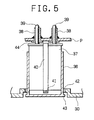
- FIG. 5 shows the interrelation among the resonator (37), chassis (30), printed circuit board (P) and a connector (38) for the resonator mounted on the printed circuit board (P).
- the printed circuit board (P) is supported on the upper side of the chassis (30) in such manner that it can be removed and fitted, and it is fitted with connectors (38) for the resonator by means of, for example, soldering.
- the connectors (38) for the resonator have a collar (44) at their bottom and they also have a section deformed by, for instance, pressure work so that they can hold the resonator.
- (39) is pins of the resonator (37) which, when inserted into the connectors (38), are electrically connected with the circuit pattern formed on the printed circuit board (P), and at the same time, the said deformed section of the connectors (38) hold the pointed end of the pins (39) of the resonator (37) mechanically.
- (40) is a band with a tab, which band (40) is intended to enclose the resonator (37) vertically and to pull out the resonator for replacement.
- (42) is a hole for replacing the resonator which is perforated in a portion of the chassis (30) that corresponds to the position of the connectors (38).
- the protrusion (43) of the cap (36) exposed from the hole for replacing the resonator should be pulled out, for instance, by hand toward the lower end, namely the outside, of the chassis (30), and only the cap will be pulled out. Or else, both the cap and the resonator (37) will be pulled out.
- the resonator (37) and the connectors (38) can be decoupled by picking up the tab (41) of the band (40) between one's fingers and pulling it, thus allowing replacement of the resonator with one having different oscillation frequency.
- the said connectors (38) may have a different construction from that mentioned above, and standard and other commercially available connectors, for example, may be used. What is important is that the connectors must have the ability to hold the pins of the resonator in position.
- the switch (33) of the model car (R) should be set to the CH/OFF position; insertion of the plug (13) of the transmitter into the charging jack (34) of the model car (R) will start recharging of the nickel cadmium battery. While the battery is recharged, the lamp (23) turns on and off. The lamp (23) will get lit steady in approx. 45 seconds, which indicates the completion of the recharging process.
- the switch (22) of the transmitter (T) should be returned to the OFF position, and concurrently, the charging lever (2) should be released, which will actuate the spring (9) to return the slider (5) to the original position with the guide member (4) as a guide.
- the plug (13) will be taken into the original position inside the case assembly (1), and the charging lever (2) will be returned to the original position, with the transmitter (T) ready to start the next round of recharging procedures as well as to perform its proper function as a transmitter.
- model car (R) On the completion of recharging of the secondary battery, the model car (R) also becomes ready to be controlled by the transmitter.
- model car Although the embodiment of the present invention described herein is in the form of model car, this invention can also apply to a model plane, a model ship and other model vehicles.
- a remotely-controlled toy that represents the present invention has great possibilities of industrial use as a device for the recharging secondary battery contained in the model vehicle and as a mechanism for replacing a crystal resonator included in the same model vehicle.
Landscapes
- Engineering & Computer Science (AREA)
- Computer Networks & Wireless Communication (AREA)
- Toys (AREA)
Applications Claiming Priority (2)
| Application Number | Priority Date | Filing Date | Title |
|---|---|---|---|
| JP10219/90 | 1990-02-06 | ||
| JP1990010219U JPH03101997U (de) | 1990-02-06 | 1990-02-06 |
Publications (2)
| Publication Number | Publication Date |
|---|---|
| EP0440900A2 true EP0440900A2 (de) | 1991-08-14 |
| EP0440900A3 EP0440900A3 (en) | 1991-11-06 |
Family
ID=11744166
Family Applications (1)
| Application Number | Title | Priority Date | Filing Date |
|---|---|---|---|
| EP19900122667 Withdrawn EP0440900A3 (en) | 1990-02-06 | 1990-11-27 | Remotely-controlled toy |
Country Status (3)
| Country | Link |
|---|---|
| US (1) | US5158495A (de) |
| EP (1) | EP0440900A3 (de) |
| JP (1) | JPH03101997U (de) |
Cited By (1)
| Publication number | Priority date | Publication date | Assignee | Title |
|---|---|---|---|---|
| NL9201544A (nl) * | 1992-09-04 | 1994-04-05 | Muco Ind B V | Regelaar voor elektrische modelauto. |
Families Citing this family (46)
| Publication number | Priority date | Publication date | Assignee | Title |
|---|---|---|---|---|
| US5524368A (en) * | 1994-03-01 | 1996-06-11 | Sno-Way International, Inc. | Wireless snow plow control system |
| USD366296S (en) | 1995-02-13 | 1996-01-16 | Novak Joseph R | Remote control model car |
| US5803789A (en) * | 1995-12-29 | 1998-09-08 | Dean; Bryan L. | Remote control toy including tilt switch hand controller |
| USD390613S (en) | 1996-05-09 | 1998-02-10 | Futaba Denshi Kogyo K.K. | Radio remote control unit |
| SE9602796L (sv) * | 1996-07-17 | 1998-01-18 | Volvo Ab | Fjärrkontroll |
| USD411265S (en) | 1996-08-09 | 1999-06-22 | Futaba Denshi Kogyo K.K. | Radio remote control unit |
| USD464684S1 (en) | 2001-11-09 | 2002-10-22 | Futaba Corporation | Radio remote control unit |
| USD480117S1 (en) | 2002-04-19 | 2003-09-30 | Nikko Co., Ltd. | Remote control |
| DE60230452D1 (de) * | 2002-04-23 | 2009-01-29 | Ccp Co Ltd | Steuergerät mit pistolengriff |
| USD481080S1 (en) | 2002-05-01 | 2003-10-21 | Futaba Corporation | Radio remote control unit |
| JP4047625B2 (ja) * | 2002-05-15 | 2008-02-13 | 双葉電子工業株式会社 | ラジオコントロール送信機 |
| US6691435B1 (en) | 2002-09-25 | 2004-02-17 | Sno-Way International, Inc. | Plow system including a hydraulic fluid diverter |
| US7288917B2 (en) * | 2002-09-30 | 2007-10-30 | Radio Shack Corporation | Transmitter for radio-controlled toy |
| AU2003277008A1 (en) * | 2002-09-30 | 2004-04-23 | Radioshack Corporation | Radio-controlled toy and transmitter |
| US6945840B2 (en) * | 2002-09-30 | 2005-09-20 | Radioshack Corporation | Wheel assembly for a toy |
| US6957996B2 (en) * | 2002-09-30 | 2005-10-25 | Radioshack Corporation | Toy car kit |
| USD485587S1 (en) | 2002-09-30 | 2004-01-20 | Radioshack Corporation | Radio frequency toy controller |
| US6913507B2 (en) * | 2002-09-30 | 2005-07-05 | Radioshack Corporation | Assembly for retaining a toy |
| USD478638S1 (en) | 2002-10-21 | 2003-08-19 | Nikko Co., Ltd. | Remote controller |
| JPWO2004064965A1 (ja) * | 2003-01-17 | 2006-05-18 | 株式会社ニッコー | 無線操縦用送信機 |
| US7374489B2 (en) * | 2003-05-28 | 2008-05-20 | Charles Sexton | Steering wheel adapted for connection to finger dial of RC control unit |
| USD524880S1 (en) * | 2003-06-05 | 2006-07-11 | Golden Bright Manufacturer Ltd. | Chassis for radio control toy car |
| USD521573S1 (en) | 2003-10-08 | 2006-05-23 | Futaba Corporation | Radio remote control unit |
| USD503439S1 (en) * | 2003-10-08 | 2005-03-29 | Radioshack Corporation | Radio frequency toy controller |
| US7029363B2 (en) * | 2003-10-08 | 2006-04-18 | Radioshack Corporation | Adjustable steering mechanism for radio frequency toy controller |
| USD524382S1 (en) | 2003-10-08 | 2006-07-04 | Futaba Corporation | Radio remote control unit |
| USD525320S1 (en) | 2003-10-27 | 2006-07-18 | Futaba Corporation | Radio remote control unit |
| USD502968S1 (en) * | 2003-12-03 | 2005-03-15 | Nikko Co., Ltd. | Remote control |
| USD503199S1 (en) * | 2004-01-27 | 2005-03-22 | Nikko Electronics Bhd. | Remote controller |
| USD516137S1 (en) * | 2004-01-28 | 2006-02-28 | Hobbyengine Model Industrial Ltd. | Radio controller for model car |
| US7628671B2 (en) * | 2004-11-26 | 2009-12-08 | Silverlit Toys Manufactory Ltd. | Programmable flying object |
| USD515635S1 (en) * | 2004-12-24 | 2006-02-21 | Nikko Co., Ltd. | Remote control |
| USD518117S1 (en) * | 2004-12-24 | 2006-03-28 | Nikko Co. Ltd. | Remote control |
| USD515636S1 (en) * | 2004-12-24 | 2006-02-21 | Nikko Co., Ltd. | Remote control |
| US7438148B1 (en) * | 2005-01-31 | 2008-10-21 | Dominick Crea | Child motorized riding toy with remote control |
| US20060180708A1 (en) * | 2005-02-14 | 2006-08-17 | Fontenot Victor Jr | R/C cockpit |
| WO2007027937A2 (en) * | 2005-08-31 | 2007-03-08 | Jakks Pacific, Inc. | Attachable drive mechanism for motoring a non-motorized toy vehicle |
| USD546905S1 (en) | 2005-11-30 | 2007-07-17 | Futaba Corporation | Radio remote control unit |
| US8371896B2 (en) * | 2008-01-14 | 2013-02-12 | Mattel, Inc. | Method and apparatus for performing try-me and normal play routines |
| US8002606B2 (en) | 2008-03-31 | 2011-08-23 | Mattel, Inc. | Trim adjustment for toy vehicle steering |
| US7938709B2 (en) * | 2008-06-26 | 2011-05-10 | Vladimir Leonov | Steering mechanism for a toy vehicle |
| US8740708B2 (en) * | 2011-05-27 | 2014-06-03 | Performance Designed Products Llc | Gun handle attachment for game controller |
| US10105616B2 (en) * | 2012-05-25 | 2018-10-23 | Mattel, Inc. | IR dongle with speaker for electronic device |
| US9427672B2 (en) | 2013-02-07 | 2016-08-30 | Objex Design | Stunt arenas for remote control vehicles |
| US10620623B2 (en) * | 2016-12-23 | 2020-04-14 | Verizon Patent And Licensing Inc. | UAV flight control system |
| JP7213777B2 (ja) * | 2019-09-09 | 2023-01-27 | 双葉電子工業株式会社 | ラジオコントロール送信機 |
Family Cites Families (12)
| Publication number | Priority date | Publication date | Assignee | Title |
|---|---|---|---|---|
| US3629680A (en) * | 1970-04-17 | 1971-12-21 | Mattel Inc | Toy battery charger |
| DE2033597A1 (de) * | 1970-07-07 | 1971-09-09 | Neuhierl H | Ladegerat fur Spielzeuge |
| US4188750A (en) * | 1977-10-31 | 1980-02-19 | Lohr Raymond J | Control cable |
| US4166338A (en) * | 1978-02-03 | 1979-09-04 | Shinsei Kogyo Co., Ltd. | Steering system for radio or wire controlled traveling toys |
| DE3008604C2 (de) * | 1980-03-06 | 1982-01-14 | Hermann Dr. 8510 Fürth Neuhierl | Sender zur Funkfernsteuerung eines Spielfahrzeuges |
| US4327517A (en) * | 1980-12-15 | 1982-05-04 | Mattel, Inc. | Steering mechanism for scale model vehicles |
| US4406085A (en) * | 1981-12-21 | 1983-09-27 | Mattel, Inc. | Modular radio control for use with multiple toy vehicles |
| JPS6073595U (ja) * | 1983-10-27 | 1985-05-23 | 株式会社トミー | 玩具用切替装置 |
| JPS6076995U (ja) * | 1983-11-02 | 1985-05-29 | 株式会社ニツコー | 充電可能な無線操縦玩具 |
| US4697133A (en) * | 1985-08-23 | 1987-09-29 | Grigorios Pergandis | Rechargeable battery powered toy |
| US4943256A (en) * | 1988-01-11 | 1990-07-24 | Pn International Corp. | Amusement device propelled by an eccentric apparatus |
| GB2219873A (en) * | 1988-06-16 | 1989-12-20 | Senoc Corp | Controller for a radio-controlled car provided with a speed display device |
-
1990
- 1990-02-06 JP JP1990010219U patent/JPH03101997U/ja active Pending
- 1990-11-27 EP EP19900122667 patent/EP0440900A3/en not_active Withdrawn
- 1990-11-28 US US07/619,003 patent/US5158495A/en not_active Expired - Fee Related
Cited By (1)
| Publication number | Priority date | Publication date | Assignee | Title |
|---|---|---|---|---|
| NL9201544A (nl) * | 1992-09-04 | 1994-04-05 | Muco Ind B V | Regelaar voor elektrische modelauto. |
Also Published As
| Publication number | Publication date |
|---|---|
| EP0440900A3 (en) | 1991-11-06 |
| US5158495A (en) | 1992-10-27 |
| JPH03101997U (de) | 1991-10-23 |
Similar Documents
| Publication | Publication Date | Title |
|---|---|---|
| EP0440900A2 (de) | Fernbedienbares Spielzeug | |
| JPH0234952Y2 (de) | ||
| JP3041000B2 (ja) | 無線操縦走行玩具の電池収納部 | |
| CN100473503C (zh) | 具有两件式电动机壳体及法兰连接上的单独的传动装置单元的可充电式旋拧/钻孔工具 | |
| US3733744A (en) | Power module for driving vehicle-propelling element,including stationary axle means mounting said element | |
| US4191917A (en) | Battery pack rechargeable in recessed or flush-type receptacles | |
| CA1233987A (en) | Rechargeable toy electric vehicle set | |
| JP3463344B2 (ja) | 充電式走行玩具、走行玩具用充電装置、及び走行玩具用走行路 | |
| JP3182855U (ja) | 車両用補助給電装置 | |
| US3947743A (en) | Electric charger | |
| US20190353128A1 (en) | Electric starter battery for large engines | |
| US10173512B1 (en) | Battery mounting device for an electric all terrain vehicle or an electric utility vehicle | |
| US20120028538A1 (en) | Electrical charger for rechargeable electrical wireless unit | |
| US20020132556A1 (en) | Toy vehicle remote controller | |
| AU731748B2 (en) | Charger/launcher for fast recharge toy vehicle | |
| EP1174976A1 (de) | Ladeeinrichtung auf einem Fahrzeug zur Ladung eines Elektrischenfahrads oder eines Rollers | |
| US20050176345A1 (en) | Transmitter for radio-controlled toy | |
| US6821184B1 (en) | Steering alignment system for a toy car | |
| JPH07315138A (ja) | 携帯電話機ホルダー | |
| JPH032320Y2 (de) | ||
| JP2004283476A (ja) | 手動発電玩具 | |
| JPH0716357A (ja) | ラジコンカー | |
| JP2004290637A (ja) | ラジオコントロール受信機 | |
| KR102796260B1 (ko) | 건전지 및 그의 충전장치 | |
| CN214311322U (zh) | 中板装配电波时钟 |
Legal Events
| Date | Code | Title | Description |
|---|---|---|---|
| PUAI | Public reference made under article 153(3) epc to a published international application that has entered the european phase |
Free format text: ORIGINAL CODE: 0009012 |
|
| AK | Designated contracting states |
Kind code of ref document: A2 Designated state(s): BE DE FR GB |
|
| PUAL | Search report despatched |
Free format text: ORIGINAL CODE: 0009013 |
|
| AK | Designated contracting states |
Kind code of ref document: A3 Designated state(s): BE DE FR GB |
|
| 17P | Request for examination filed |
Effective date: 19920504 |
|
| 17Q | First examination report despatched |
Effective date: 19930804 |
|
| STAA | Information on the status of an ep patent application or granted ep patent |
Free format text: STATUS: THE APPLICATION IS DEEMED TO BE WITHDRAWN |
|
| 18D | Application deemed to be withdrawn |
Effective date: 19931215 |