EP0441025A2 - Conduit - Google Patents
Conduit Download PDFInfo
- Publication number
- EP0441025A2 EP0441025A2 EP90309795A EP90309795A EP0441025A2 EP 0441025 A2 EP0441025 A2 EP 0441025A2 EP 90309795 A EP90309795 A EP 90309795A EP 90309795 A EP90309795 A EP 90309795A EP 0441025 A2 EP0441025 A2 EP 0441025A2
- Authority
- EP
- European Patent Office
- Prior art keywords
- shell
- conduit according
- insulating material
- layer
- segments
- Prior art date
- Legal status (The legal status is an assumption and is not a legal conclusion. Google has not performed a legal analysis and makes no representation as to the accuracy of the status listed.)
- Ceased
Links
Images

Classifications
-
- F—MECHANICAL ENGINEERING; LIGHTING; HEATING; WEAPONS; BLASTING
- F16—ENGINEERING ELEMENTS AND UNITS; GENERAL MEASURES FOR PRODUCING AND MAINTAINING EFFECTIVE FUNCTIONING OF MACHINES OR INSTALLATIONS; THERMAL INSULATION IN GENERAL
- F16L—PIPES; JOINTS OR FITTINGS FOR PIPES; SUPPORTS FOR PIPES, CABLES OR PROTECTIVE TUBING; MEANS FOR THERMAL INSULATION IN GENERAL
- F16L59/00—Thermal insulation in general
- F16L59/12—Arrangements for supporting insulation from the wall or body insulated, e.g. by means of spacers between pipe and heat-insulating material; Arrangements specially adapted for supporting insulated bodies
-
- F—MECHANICAL ENGINEERING; LIGHTING; HEATING; WEAPONS; BLASTING
- F16—ENGINEERING ELEMENTS AND UNITS; GENERAL MEASURES FOR PRODUCING AND MAINTAINING EFFECTIVE FUNCTIONING OF MACHINES OR INSTALLATIONS; THERMAL INSULATION IN GENERAL
- F16L—PIPES; JOINTS OR FITTINGS FOR PIPES; SUPPORTS FOR PIPES, CABLES OR PROTECTIVE TUBING; MEANS FOR THERMAL INSULATION IN GENERAL
- F16L59/00—Thermal insulation in general
- F16L59/14—Arrangements for the insulation of pipes or pipe systems
- F16L59/16—Arrangements specially adapted to local requirements at flanges, junctions, valves or the like
- F16L59/18—Arrangements specially adapted to local requirements at flanges, junctions, valves or the like adapted for joints
- F16L59/20—Arrangements specially adapted to local requirements at flanges, junctions, valves or the like adapted for joints for non-disconnectable joints
-
- F—MECHANICAL ENGINEERING; LIGHTING; HEATING; WEAPONS; BLASTING
- F16—ENGINEERING ELEMENTS AND UNITS; GENERAL MEASURES FOR PRODUCING AND MAINTAINING EFFECTIVE FUNCTIONING OF MACHINES OR INSTALLATIONS; THERMAL INSULATION IN GENERAL
- F16L—PIPES; JOINTS OR FITTINGS FOR PIPES; SUPPORTS FOR PIPES, CABLES OR PROTECTIVE TUBING; MEANS FOR THERMAL INSULATION IN GENERAL
- F16L59/00—Thermal insulation in general
- F16L59/14—Arrangements for the insulation of pipes or pipe systems
- F16L59/16—Arrangements specially adapted to local requirements at flanges, junctions, valves or the like
- F16L59/21—Arrangements specially adapted to local requirements at flanges, junctions, valves or the like adapted for expansion-compensation devices
-
- Y—GENERAL TAGGING OF NEW TECHNOLOGICAL DEVELOPMENTS; GENERAL TAGGING OF CROSS-SECTIONAL TECHNOLOGIES SPANNING OVER SEVERAL SECTIONS OF THE IPC; TECHNICAL SUBJECTS COVERED BY FORMER USPC CROSS-REFERENCE ART COLLECTIONS [XRACs] AND DIGESTS
- Y10—TECHNICAL SUBJECTS COVERED BY FORMER USPC
- Y10S—TECHNICAL SUBJECTS COVERED BY FORMER USPC CROSS-REFERENCE ART COLLECTIONS [XRACs] AND DIGESTS
- Y10S248/00—Supports
- Y10S248/901—Support having temperature or pressure responsive feature
Definitions
- the invention relates generally to conduits and particularly to insulated conduits.
- a conduit 10 is used to transport solids, and typically comprises a steel shell 12 lined internally with a multi-layer refractory composite 14.
- the refractory composite 14 typically comprises an insulating refractory layer 16 on the inner surface 18 of the steel shell 12 and a dense, "erosion resistant" refractory layer 20 covering the insulating refractory layer 16 and forming a passage 21 with an inside diameter 22 of the conduit 10.
- the hot particulate matter is conveyed within the passage 21.
- the support for the refractory composite 14 is generally by anchors 24 welded to the inner surface 18 of the steel shell 12. Separate anchors 24 may be provided for each layer of refractory 16, 20.
- the temperature of the solids is likely to be in the range 815 o C to 982 o C (1500 o F to 1800 o F), but lower temperatures are possible.
- the dense erosion resistant refractory 20 at the inner diameter 22 is at the same temperature as the hot particulate matter conveyed through the conduit 10, while the temperature at an outside diameter of the steel shell 12 is typically in the range of 73.8 o C to 107.2 o C (165 o F to 225 o F).
- the properties of the refractory 16, 20 vary widely depending on vendor supply, application and process. However, the common properties of this construction are:
- the problems with this construction are: (1) Failures of the refractory 16, 20 and (2) damage to the steel shell 12 due to overheating when the internal refractory layers fail.
- the temperature of the conduit 10 increases from ambient to operating temperature.
- the conduit 10 is heated from the inner diameter 22, since the solids conveyed thereby are the source of the heat. Heating causes the dense refractory 20 to expand radially and since the rate of heating of the insulating refractory 16 and the steel shell 12 lags behind the rate of heating of the dense refractory 20, the dense refractory 20 compresses the insulating refractory 16 causing stresses that exceed the crushing strength of the insulating refractory 16.
- the steel shell 12 is generally oriented vertically.
- the stresses on the anchors 24 are due to bending from the cantilever loading of the refractory 16, 20 thereon. This cantilever loading on the anchors 24 increases as deterioration of the insulating refractory 16 continues.
- the anchors 24 bend the stress in the dense refractory 20 is concentrated at and along each anchor 24. This point/line tension loading on the dense refractory 20 causes cracks. Ultimately, the cracks propagate through the dense refractory 20 and pieces of the dense refractory 20 fall out, which is defined as a failure of the insulated conduit 10.
- a conduit comprising: a shell having an internal surface; a layer of insulating material located within the shell and forming an inner passage through which a high temperature material can be conveyed; and a shelf, engaged with the internal surface, to support the insulating material within the shell against the force of gravity without restraining movement of the insulating material due to thermal expansion thereof.
- a conduit comprising: a first shell, and a second shell; each of the shells having a layer of insulating material located therein and forming an inner passage therethrough through which a high temperature material can be conveyed and a shelf, engaged with an internal surface of each respective shell to support the insulating material within each of the shells against the force of gravity without restraining movement of the insulating material due to thermal expansion thereof, the first shell being stacked upon the second shell to form a continuous inner passage through the shells; and means to secure the first shell to the second shell.
- a conduit comprising: a cylindrical shell having an internal surface; a layer of refractory material within the shell and forming an inner passage through which a high temperature can be conveyed; a layer of insulating fibre board, located between the layer of refractory material and the internal surface, which crushes when the refractory material undergoes radial thermal expansion to prevent excessive hoop stresses in the shell; and an annular shelf to support the refractory material within the shell against the force of gravity without restraining radial movement of the refractory material due to thermal expansion thereof.
- Such a construction can avoid deterioration of the dense refractory due to thermal cycling, can minimise or eliminate hoop stresses in the pipe due to thermal expansion of the refractory contained therein and can eliminate point/line tension loading on the refractory caused by anchors.
- Figure 1 is a sectional view through a typical insulated conduit of previously proposed kind
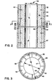
- Figure 2 is a sectional view through two sections of insulated conduit according to an embodiment of the invention, stacked one on top of the other
- Figure 3 is a sectional view taken on line 3-3 of Figure 2, with insulating material omitted for clarity.
- a conduit 30 to convey a high temperature particulate material therethrough is typically cylindrical in cross-section but other geometric cross-sections could be used.
- the conduit 30 comprises a pipe or shell 32 having an inner surface 34.
- the shell 32 is generally made of carbon steel.
- a layer of insulating fibre board 36 is placed on the inner surface 34 of the shell 32.
- the insulating fibre board 36 is made from a material according to ASTM C 612 Class 5 HT block so that it readily deforms when a load is applied to a surface thereof.
- ASTM C 612 Class 5 HT block One supplier of such a material is US Gypsum under the name K-FAC 19.
- An inner layer of dense erosion-resistant refractory 38 is applied inside of and on top of the layer of insulating fibre board 36, to provide an inner surface 40, 41 with an inside diameter defining a passage 41 through which high temperature material can be conveyed.
- the layer of dense refractory 38 is advantageously a fused silica product.
- One supplier of such a material is North American Refractories Company under the name HPV-SX. This material has good insulating properties for a dense refractory but it is chosen primarily for its shock resistance and erosion resistance properties.
- HPV-SX North American Refractories Company
- This material has good insulating properties for a dense refractory but it is chosen primarily for its shock resistance and erosion resistance properties.
- the layer of dense refractory 38 Upon heating, the layer of dense refractory 38 will expand, loading and compressing the layer of fibre board 36 between the layer of dense refractory 38 and the inner surface 34 of the shell 32.
- the deformable nature of the layer of insulating fibre board 36 allows these thermally induced applied loads simply to crush the layer of insulating fibre board 36, absorbing the thermally induced loading. As a result, the pressure loads actually applied to the inner surface 34 of the shell 32 are reduced to a neg
- annular shelf 44 is provided to support the layer of dense refractory 38 against the force of gravity.
- the anchors 42 are still used to manufacture the conduit 30, and to "key" the layer of dense refractory 38 together should cracks still develop therein due to thermal cycling.
- the annular shelf 44 allows the layer of dense refractory 38 to expand and contract during temperature cycles, without restraining movement thereof, thereby avoiding tensile stresses which could cause the layer of dense refractory 38 to fail.
- the annular shelf 44 comprises a plurality of separate annular segments 46 having a thickness t and a width w and separated from one another by expansion gaps 48.
- the annular segments 46 are generally made of stainless steel.
- the expansion gaps 48 are relatively equally spaced about the periphery of the annular shelf 44.
- An inner diameter 50 defined by the annular segments 46 is chosen to be slightly greater than that of the inner diameter 40 defining the passage through which the high temperature material is conveyed.
- the annular segments 46 act like an extended surface fin whose overall design temperature increases the closer the tip 47 of each annular segment 46 comes to the passage of the conduit 30.
- the tips 47 of the annular segments 46 covered by the layer of dense refractory 38, heat transfer to the annular segments 46 is reduced thereby lowering the design temperature of the annular segments 46.
- the temperature at the inner diameter 50 of the annular shelf 44 can be nearly 537.7 o C (1000 o F) while the temperature at an outside diameter 52 of the annular shelf 44 would be only about 176.6 o C (350 o F).
- This severe temperature differential would cause the annular shelf 44 to bend into a cone shape, much like a BELLEVILLE washer, were it not for the presence of the expansion gaps 48 which divide the annular shelf 44 into the plurality of annular segments 46. This bending would cause the layer of dense refractory 38 to move, applying a load to the anchors 42 which would cause cracking of the layer of dense refractory 38.
- the expansion gaps 48 prevent the aforementioned cone-shaped bending of the annular shelf 44.
- Shear lugs 54 welded or otherwise affixed to the inner surface 34 of the shell 32, transmit the load on the annular shelf 44, due to the weight of the layer of dense refractory 38 and layer of insulating fibre board 36, to the shell 32.
- the number of shear lugs 54 is determined by the load to be supported; the shear lugs are also generally made of carbon steel.
- a curved plate 56 is welded or otherwise affixed along the outer periphery at the outside diameter 52 of each of the annular segments 46. This creates an "L-shape" in cross section being formed by the curved plate 56 and each annular segment 46.
- annular segments 46 and curved plate 56 could be fabricated together as a single, one-piece member.
- Right angle clips 58 are welded to the inner surface 34 of the shell 32 above the curved plate 56, but they are not welded or affixed to the curved plate 56. The right angle clips 58 engage the curved plate 56, thereby transmitting the rotational load on each annular segment 46 to the shell 32, and are also generally made of carbon steel.
- the annular segments 46 rest in an unrestrained fashion upon the shear lugs 54, "tied” to the shell 32 with only one right angle clip 58 for each annular segment 46.
- the described construction allows for movement of the annular segments 46 horizontally/radially in an unrestrained fashion due to the thermally induced expansions, thus nearly eliminating any warping or unwanted movement of the annular segments 46.
- annular shelf 44 is divided into a plurality of annular segments 46, separated from one another by expansion gaps 48.
- the choice of the exact number of annular segments 46 is a function of several factors. While Figure 3 shows eight annular segments, fewer annular segments 46 can be employed, and in such a design each annular segment 46 will carry a larger proportional part of the weight of the layer of dense refractory 38.
- the thickness t of each radial segment 46 is set by calculations of the bending stress at the intersection of the curved plate 56 with each annular segment 46. It is generally preferred that the width w of each annular segment 46 be approximately three quarters of the thickness of the layer of dense refractory 38 that will be supported thereby.
- each annular segment 46 Since only one right angle clip 58 is preferred for each annular segment 46, providing fewer but larger annular segments 46 will require larger and stronger clips 58 to prevent rotation of each of the annular segments 46. This can only be done up to a point, since the rotational load is eventually transmitted to the wall of the shell 32 at the affixation point of each right angle clip 58 to the inner surface 34 of the shell 32. If the load on each annular segment 46 becomes too great, the transmitted load to the shell 32 will cause localised kinking or deformation of the wall of the shell 32. Additionally, using fewer annular segments 46 increases the possibility that they will deform into a cone-shape when subjected to the thermal heating cycles. This is unacceptable since it will tend to move the layer of dense refractory 38 causing the aforementioned destructive point/line loading of the anchors 42 onto the layer of dense refractory 38.
- the inner surface 41 at the inner diameter 40 of the dense refractory 38 was visually examined after each temperature cycle, and after the test series one of the fabricated sections was destructively examined. The results showed no cracking of the layer of dense refractory 38 due to expansion of the annular shelf 44, or due to point/line loading of the anchors 42 on the layer of dense refractory 38.
- the annular segments 46 of the annular shelf 44 showed no signs of warping or displacement even though there was a 177.7 o C to 537.7 o C (350 o F) to 1000 o F) temperature differential across the width w of the annular segments 46 combined with the gravity loading of the refractory mass thereon.
- the annular segments 46 remained perpendicular to the curved plates 56, expanding freely without inducing shear forces on the layer of dense refractory 38, and the anchors 42 were not loaded by bending forces. As a result, a nearly crack free layer of dense refractory 38 was preserved.
- a conduit of the invention can be easily modularised into sections of any convenient length, each section being stacked upon an adjacent section.
- An expansion joint 60 using a gasket preferably made of KAOWOOL or other similar material would be placed between each section and a girth weld 62 would secure one section to another.
- the present insulated pipe construction is for use in the conveying of high temperature material such as is encountered in fluidised bed combustion boilers
- the invention can be used in any application where a hot gaseous or fluid medium alone or in combination with high temperature particulate material is conveyed via an insulated conduit.
Landscapes
- Engineering & Computer Science (AREA)
- General Engineering & Computer Science (AREA)
- Mechanical Engineering (AREA)
- Thermal Insulation (AREA)
Abstract
An insulated conduit (30) avoids deterioration of refractory material (38) due to thermal cycling by providing a shelf (44) to support the refractory material (38) against the force of gravity without restraining movement of the refractory material (38) due to thermal expansion thereof. Excessive hoop stresses in the shell (32) of the conduit (30) due to thermal expansion of the refractory material can be prevented by providing a crushable layer (36) of insulating fibre board between the refractory material (38) and the inner surface (34) of the shell (32).
Description
- The invention relates generally to conduits and particularly to insulated conduits.
- In a fluidised bed boiler, there is a need to collect hot particulate matter (solids) and return the solids back to the furnace combustion zone. As shown in Figure 1 of the accompanying drawings, a
conduit 10 is used to transport solids, and typically comprises asteel shell 12 lined internally with a multi-layerrefractory composite 14. Therefractory composite 14 typically comprises an insulatingrefractory layer 16 on theinner surface 18 of thesteel shell 12 and a dense, "erosion resistant"refractory layer 20 covering the insulatingrefractory layer 16 and forming a passage 21 with aninside diameter 22 of theconduit 10. The hot particulate matter is conveyed within the passage 21. The support for therefractory composite 14 is generally byanchors 24 welded to theinner surface 18 of thesteel shell 12.Separate anchors 24 may be provided for each layer ofrefractory - During normal operation, high temperature solids are conveyed through the
conduit 10. The temperature of the solids is likely to be in the range 815oC to 982oC (1500oF to 1800oF), but lower temperatures are possible. At temperature equilibrium, the dense erosionresistant refractory 20 at theinner diameter 22 is at the same temperature as the hot particulate matter conveyed through theconduit 10, while the temperature at an outside diameter of thesteel shell 12 is typically in the range of 73.8oC to 107.2oC (165oF to 225oF). - The properties of the
refractory - 1. The
insulating refractory 16 is typically cast or gunned onto theinner face 18 of thesteel pipe 12. However, the greater the need for insulating quality the lower the strength of the insulatingrefractory layer 16. - 2. The dense
refractory layer 20 is also typically cast or gunned. This denserefractory layer 20 has significantly higher weight and strength than the insulatingrefractory layer 16. - The problems with this construction are: (1) Failures of the refractory 16, 20 and (2) damage to the
steel shell 12 due to overheating when the internal refractory layers fail. During start-up, the temperature of theconduit 10 increases from ambient to operating temperature. Theconduit 10 is heated from theinner diameter 22, since the solids conveyed thereby are the source of the heat. Heating causes the dense refractory 20 to expand radially and since the rate of heating of the insulating refractory 16 and thesteel shell 12 lags behind the rate of heating of the dense refractory 20, the dense refractory 20 compresses theinsulating refractory 16 causing stresses that exceed the crushing strength of theinsulating refractory 16. Additionally, this thermal loading is transmitted to thesteel shell 12, causing extremely high hoop stresses therein which could exceed the yield strength of the steel from which it is made. Successive heat-up and cool-down cycles continue the process, tending to crush the insulatingrefractory 16, leading to overheating and possibly yielding of thesteel pipe 12. - The
steel shell 12 is generally oriented vertically. When theanchors 24 are the only means of vertical support against the force of gravity for thedense refractory 20, the stresses on theanchors 24 are due to bending from the cantilever loading of therefractory anchors 24 increases as deterioration of theinsulating refractory 16 continues. When theanchors 24 bend, the stress in thedense refractory 20 is concentrated at and along eachanchor 24. This point/line tension loading on the dense refractory 20 causes cracks. Ultimately, the cracks propagate through the dense refractory 20 and pieces of thedense refractory 20 fall out, which is defined as a failure of the insulatedconduit 10. - According to one aspect of the invention there is provided a conduit, comprising:
a shell having an internal surface;
a layer of insulating material located within the shell and forming an inner passage through which a high temperature material can be conveyed; and
a shelf, engaged with the internal surface, to support the insulating material within the shell against the force of gravity without restraining movement of the insulating material due to thermal expansion thereof. - According to another aspect of the invention there is provided a conduit, comprising:
a first shell, and a second shell; each of the shells having a layer of insulating material located therein and forming an inner passage therethrough through which a high temperature material can be conveyed and a shelf, engaged with an internal surface of each respective shell to support the insulating material within each of the shells against the force of gravity without restraining movement of the insulating material due to thermal expansion thereof, the first shell being stacked upon the second shell to form a continuous inner passage through the shells; and
means to secure the first shell to the second shell. - According to a further aspect of the invention there is provided a conduit, comprising:
a cylindrical shell having an internal surface;
a layer of refractory material within the shell and forming an inner passage through which a high temperature can be conveyed;
a layer of insulating fibre board, located between the layer of refractory material and the internal surface, which crushes when the refractory material undergoes radial thermal expansion to prevent excessive hoop stresses in the shell; and
an annular shelf to support the refractory material within the shell against the force of gravity without restraining radial movement of the refractory material due to thermal expansion thereof. - Such a construction can avoid deterioration of the dense refractory due to thermal cycling, can minimise or eliminate hoop stresses in the pipe due to thermal expansion of the refractory contained therein and can eliminate point/line tension loading on the refractory caused by anchors.
- The invention is diagrammatically illustrated by way of example in the accompanying drawings, in which Figure 1 is a sectional view through a typical insulated conduit of previously proposed kind;
Figure 2 is a sectional view through two sections of insulated conduit according to an embodiment of the invention, stacked one on top of the other; and
Figure 3 is a sectional view taken on line 3-3 of Figure 2, with insulating material omitted for clarity. - Referring to Figures 2 and 3, a
conduit 30 to convey a high temperature particulate material therethrough is typically cylindrical in cross-section but other geometric cross-sections could be used. - The
conduit 30 comprises a pipe orshell 32 having aninner surface 34. Theshell 32 is generally made of carbon steel. A layer of insulatingfibre board 36 is placed on theinner surface 34 of theshell 32. The insulatingfibre board 36 is made from a material according to ASTM C 612 Class 5 HT block so that it readily deforms when a load is applied to a surface thereof. One supplier of such a material is US Gypsum under the name K-FAC 19. An inner layer of dense erosion-resistant refractory 38 is applied inside of and on top of the layer of insulatingfibre board 36, to provide aninner surface 40, 41 with an inside diameter defining apassage 41 through which high temperature material can be conveyed. - The layer of dense refractory 38 is advantageously a fused silica product. One supplier of such a material is North American Refractories Company under the name HPV-SX. This material has good insulating properties for a dense refractory but it is chosen primarily for its shock resistance and erosion resistance properties. Upon heating, the layer of dense refractory 38 will expand, loading and compressing the layer of
fibre board 36 between the layer of dense refractory 38 and theinner surface 34 of theshell 32. However, the deformable nature of the layer of insulatingfibre board 36 allows these thermally induced applied loads simply to crush the layer of insulatingfibre board 36, absorbing the thermally induced loading. As a result, the pressure loads actually applied to theinner surface 34 of theshell 32 are reduced to a negligible level or eliminated altogether, and excessive hoop stresses in theshell 32 are avoided. - Support for the layer of dense refractory 38 against the force of gravity must still be provided, however, to eliminate the point/line tension loading on the layer of dense refractory 38 caused by bending of
anchors 42. To accomplish this, anannular shelf 44 is provided to support the layer of dense refractory 38 against the force of gravity. Theanchors 42 are still used to manufacture theconduit 30, and to "key" the layer of dense refractory 38 together should cracks still develop therein due to thermal cycling. Theannular shelf 44 allows the layer of dense refractory 38 to expand and contract during temperature cycles, without restraining movement thereof, thereby avoiding tensile stresses which could cause the layer of dense refractory 38 to fail. - The
annular shelf 44 comprises a plurality of separateannular segments 46 having a thickness t and a width w and separated from one another byexpansion gaps 48. Theannular segments 46 are generally made of stainless steel. Theexpansion gaps 48 are relatively equally spaced about the periphery of theannular shelf 44. Aninner diameter 50 defined by theannular segments 46 is chosen to be slightly greater than that of the inner diameter 40 defining the passage through which the high temperature material is conveyed. By this construction,tips 47 of theannular segments 46 are not exposed to the high temperature of the material being conveyed in thepassage 41, thetips 47 being covered by the layer of dense refractory 38. Viewed from a heat transfer perspective, theannular segments 46 act like an extended surface fin whose overall design temperature increases the closer thetip 47 of eachannular segment 46 comes to the passage of theconduit 30. By keeping thetips 47 of theannular segments 46 covered by the layer of dense refractory 38, heat transfer to theannular segments 46 is reduced thereby lowering the design temperature of theannular segments 46. - During normal operation, the temperature at the
inner diameter 50 of theannular shelf 44 can be nearly 537.7oC (1000oF) while the temperature at anoutside diameter 52 of theannular shelf 44 would be only about 176.6oC (350oF). This severe temperature differential would cause theannular shelf 44 to bend into a cone shape, much like a BELLEVILLE washer, were it not for the presence of theexpansion gaps 48 which divide theannular shelf 44 into the plurality ofannular segments 46. This bending would cause the layer of dense refractory 38 to move, applying a load to theanchors 42 which would cause cracking of the layer of dense refractory 38. However, theexpansion gaps 48 prevent the aforementioned cone-shaped bending of theannular shelf 44. - Shear lugs 54, welded or otherwise affixed to the
inner surface 34 of theshell 32, transmit the load on theannular shelf 44, due to the weight of the layer of dense refractory 38 and layer of insulatingfibre board 36, to theshell 32. The number of shear lugs 54 is determined by the load to be supported; the shear lugs are also generally made of carbon steel. To prevent each of theannular segments 46 from rotating inwardly, acurved plate 56 is welded or otherwise affixed along the outer periphery at theoutside diameter 52 of each of theannular segments 46. This creates an "L-shape" in cross section being formed by thecurved plate 56 and eachannular segment 46. Alternatively, theannular segments 46 andcurved plate 56 could be fabricated together as a single, one-piece member. Right angle clips 58 are welded to theinner surface 34 of theshell 32 above thecurved plate 56, but they are not welded or affixed to thecurved plate 56. The right angle clips 58 engage thecurved plate 56, thereby transmitting the rotational load on eachannular segment 46 to theshell 32, and are also generally made of carbon steel. - The
annular segments 46 rest in an unrestrained fashion upon the shear lugs 54, "tied" to theshell 32 with only oneright angle clip 58 for eachannular segment 46. By utilising only one right angle clip for eachannular segment 46, and by placing eachright angle clip 58 generally in the middle of eachannular segment 46, binding of eachannular segment 46 is prevented when the thermal expansion occurs. Placing two or more clips on eachannular segment 46 tends to bind theannular segment 46 when it is heated causing it to warp. The described construction allows for movement of theannular segments 46 horizontally/radially in an unrestrained fashion due to the thermally induced expansions, thus nearly eliminating any warping or unwanted movement of theannular segments 46. As a result, movement of the layer of dense refractory 38 supported thereby is prevented and the aforementioned point/line loading by theanchors 42 that normally produces cracking in the layer of dense refractory 38 is prevented. Additionally, there is no need for any dissimilaf metal welds between theannular segments 46 and theshell 32, right angle clips 58 or shear lugs 54. Eventually, the thermal cycles may cause the layer of dense refractory 38 to crack but theanchors 32 will hold the pieces together for a much longer period of time, since the layer of dense refractory 38 is supported by theannular shelf 44. - As indicated previously, the
annular shelf 44 is divided into a plurality ofannular segments 46, separated from one another byexpansion gaps 48. The choice of the exact number ofannular segments 46 is a function of several factors. While Figure 3 shows eight annular segments, fewerannular segments 46 can be employed, and in such a design eachannular segment 46 will carry a larger proportional part of the weight of the layer of dense refractory 38. The thickness t of eachradial segment 46 is set by calculations of the bending stress at the intersection of thecurved plate 56 with eachannular segment 46. It is generally preferred that the width w of eachannular segment 46 be approximately three quarters of the thickness of the layer of dense refractory 38 that will be supported thereby. Since only oneright angle clip 58 is preferred for eachannular segment 46, providing fewer but largerannular segments 46 will require larger andstronger clips 58 to prevent rotation of each of theannular segments 46. This can only be done up to a point, since the rotational load is eventually transmitted to the wall of theshell 32 at the affixation point of eachright angle clip 58 to theinner surface 34 of theshell 32. If the load on eachannular segment 46 becomes too great, the transmitted load to theshell 32 will cause localised kinking or deformation of the wall of theshell 32. Additionally, using fewerannular segments 46 increases the possibility that they will deform into a cone-shape when subjected to the thermal heating cycles. This is unacceptable since it will tend to move the layer of dense refractory 38 causing the aforementioned destructive point/line loading of theanchors 42 onto the layer of dense refractory 38. - Testing was performed on fabricated sections incorporating the teachings of the invention. Two insulated 1.22m (48 inches) high sections each having a 0.76m (30 inches) inner diameter inner passage and a 1.37m (54 inches) outside diameter carbon steel shell were stacked vertically in a test stand. A burner was attached to the bottom to fire the sections with a thermocouple located on the outlet to control the firing rate. A series of 24 tests was conducted in which the inner diameter 40 of the layer of dense refractory 38 was heated from ambient temperatures to 871oC (1600oF). The number of cycles simulated 5 to 10 years of actual cycles on a boiler, and the rate of temperature increase nearly simulated the conditions of an actual boiler start-up.
- The
inner surface 41 at the inner diameter 40 of the dense refractory 38 was visually examined after each temperature cycle, and after the test series one of the fabricated sections was destructively examined. The results showed no cracking of the layer of dense refractory 38 due to expansion of theannular shelf 44, or due to point/line loading of theanchors 42 on the layer of dense refractory 38. Theannular segments 46 of theannular shelf 44 showed no signs of warping or displacement even though there was a 177.7oC to 537.7oC (350oF) to 1000oF) temperature differential across the width w of theannular segments 46 combined with the gravity loading of the refractory mass thereon. Theannular segments 46 remained perpendicular to thecurved plates 56, expanding freely without inducing shear forces on the layer of dense refractory 38, and theanchors 42 were not loaded by bending forces. As a result, a nearly crack free layer of dense refractory 38 was preserved. - Commercially, the advantage of such an insulated pipe construction is decreased maintenance costs. The typical life expectancy of the previously proposed constructions is only 1 to 2 years before total replacement of the
refractory composite 14 is required. The projected life expectancy of the present design is 5 to 10 years based upon the test data. A conduit of the invention can be easily modularised into sections of any convenient length, each section being stacked upon an adjacent section. Anexpansion joint 60 using a gasket preferably made of KAOWOOL or other similar material would be placed between each section and agirth weld 62 would secure one section to another. By prefabricating these sections, downtime of the boiler can be minimised and lost production costs greatly reduced. - While the invention has been described as being especially suitable for application to vertical conduits, advantages thereof can also be realised in any conduit where support of the layers of insulating material contained therein can be effected by the support means of the invention. While the term "dense" refractory has been used to describe the material through which the high temperature material is conveyed, it is understood that "insulating" refractories characterised by their light weight, low density and low strength could also be utilised if the erosion resistant properties of a "dense" refractory were not essential. Thus, while particular application of the present insulated pipe construction is for use in the conveying of high temperature material such as is encountered in fluidised bed combustion boilers, the invention can be used in any application where a hot gaseous or fluid medium alone or in combination with high temperature particulate material is conveyed via an insulated conduit.
Claims (20)
1. A conduit (30), comprising:
a shell (32) having an internal surface (34);
a layer of insulating material (38) located within the shell (32) and forming an inner passage through which a high temperature material can be conveyed; and
a shelf (44), engaged with the internal surface (34), to support the insulating material (38) within the shell (32) against the force of gravity without restraining movement of the insulating material due to thermal expansion thereof.
a shell (32) having an internal surface (34);
a layer of insulating material (38) located within the shell (32) and forming an inner passage through which a high temperature material can be conveyed; and
a shelf (44), engaged with the internal surface (34), to support the insulating material (38) within the shell (32) against the force of gravity without restraining movement of the insulating material due to thermal expansion thereof.
2. A conduit according to claim 1, wherein the shelf (44) is supported by shear lugs (54) attached to the internal surface (34).
3. A conduit according to claim 2, wherein the shelf (44) comprises a plurality of segments (46) separated from one another by expansion gaps (48).
4. A conduit according to claim 3, including means to prevent rotation of the segments (46) about the shear lugs (54).
5. A conduit according to claim 4, wherein the means to prevent rotation of the segments (46) about the shear lugs (54) comprises a plurality of plates (56) attached to an outer periphery of each of the segments (46) to form an is an L-shape in cross-section and a plurality of right angle clips (58), one for each of the plates (56), attached to the internal surface (34) to engage the plates (56).
6. A conduit according to claim 1, including means to prevent excessive hoop stresses in the shell due to thermal expansion of the insulating material.
7. A conduit according to claim 6, wherein the means to prevent excessive hoop stresses in the shell (32) due to thermal expansion of the insulating material comprises a layer of insulating fibre board (36), located between the layer of insulating material (38) and the internal surface (34), which crushes when the insulating material (38) undergoes thermal expansion.
8. A conduit according to claim 1, including means for keeping the insulating material together if cracks develop in the insulating material.
9. A conduit according to claim 8, wherein the means for keeping the insulating material together comprises anchors (42) attached to the internal surface (34) and imbedded in the insulating material (38).
10. A conduit according to claim 1, wherein the shell (34) is cylindrical in cross-section.
11. A conduit according to claim 1, wherein the shelf (44) is an annular shelf.
12. A conduit according to claim 3, wherein the segments (46) are annular segments.
13. A conduit, comprising:
a first shell (32), and a second shell (32); each of the shells having a layer of insulating material (38) located therein and forming an inner passage therethrough through which a high temperature material can be conveyed and a shelf (44), engaged with an internal surface (34) of each respective shell (32), to support the insulating material (38) within each of the shells against the force of gravity without restraining movement of the insulating material (38) due to thermal expansion thereof, the first shell being stacked upon the second shell to form a continuous inner passage through the sHells; and means (60, 62) to secure the first shell to the second shell.
a first shell (32), and a second shell (32); each of the shells having a layer of insulating material (38) located therein and forming an inner passage therethrough through which a high temperature material can be conveyed and a shelf (44), engaged with an internal surface (34) of each respective shell (32), to support the insulating material (38) within each of the shells against the force of gravity without restraining movement of the insulating material (38) due to thermal expansion thereof, the first shell being stacked upon the second shell to form a continuous inner passage through the sHells; and means (60, 62) to secure the first shell to the second shell.
14. A conduit according to claim 13, wherein the means to secure the first shell to the second shell comprise a gasket (60) placed between the first and second shells and a girth weld (62) connecting the first shell to the second shell.
15. A conduit, comprising:
a cylindrical shell (30) having an internal surface (34);
a layer of refractory material (38) within the shell (32) and forming an inner passage through which a high temperature material can be conveyed;
a layer of insulating fibre board (36), located between the layer of refractory material (38) and the internal surface (34), which crushes when the refractory material (38) undergoes radial thermal expansion to prevent excessive hoop stresses in the shell (32); and
an annular shelf (44) to support the refractory material (38) within the shell (32) against the force of gravity without restraining radial movement of the refractory material (38) due to thermal expansion thereof.
a cylindrical shell (30) having an internal surface (34);
a layer of refractory material (38) within the shell (32) and forming an inner passage through which a high temperature material can be conveyed;
a layer of insulating fibre board (36), located between the layer of refractory material (38) and the internal surface (34), which crushes when the refractory material (38) undergoes radial thermal expansion to prevent excessive hoop stresses in the shell (32); and
an annular shelf (44) to support the refractory material (38) within the shell (32) against the force of gravity without restraining radial movement of the refractory material (38) due to thermal expansion thereof.
16. A conduit according to claim 15, wherein the annular shelf (44) comprises a plurality of annular segments (46) separated from one another by expansion gaps (48).
17. A conduit according to claim 16, wherein the annular segments (46) are supported by shear lugs (54) attached to the internal surface (34).
18. A conduit according to claim 17, including means to prevent rotation of the annular segments (46) about the shear lugs (54).
19. A conduit according to claim 18, wherein the means to prevent rotation of the segments (46) about the shear lugs (54) comprises a plurality of curved plates (56), attached to an outer periphery of each of the annular segments (46) to form an L-shape in cross-section and a plurality of right angle clips (58) attached to the internal surface (34) to engage the plates (56).
20. A conduit according to claim 19, wherein the annular segments (46) and the curved plates (56) are fabricated together as a single, one-piece member.
Applications Claiming Priority (2)
| Application Number | Priority Date | Filing Date | Title |
|---|---|---|---|
| US07/433,622 US5078182A (en) | 1989-11-07 | 1989-11-07 | Insulated pipe construction |
| US433622 | 1989-11-07 |
Publications (2)
| Publication Number | Publication Date |
|---|---|
| EP0441025A2 true EP0441025A2 (en) | 1991-08-14 |
| EP0441025A3 EP0441025A3 (en) | 1991-10-23 |
Family
ID=23720873
Family Applications (1)
| Application Number | Title | Priority Date | Filing Date |
|---|---|---|---|
| EP19900309795 Ceased EP0441025A3 (en) | 1989-11-07 | 1990-09-07 | Conduit |
Country Status (7)
| Country | Link |
|---|---|
| US (1) | US5078182A (en) |
| EP (1) | EP0441025A3 (en) |
| JP (1) | JPH0833185B2 (en) |
| CN (1) | CN1018383B (en) |
| CA (1) | CA2020911C (en) |
| TR (1) | TR26228A (en) |
| ZA (1) | ZA904657B (en) |
Cited By (1)
| Publication number | Priority date | Publication date | Assignee | Title |
|---|---|---|---|---|
| GB2483699A (en) * | 2010-09-17 | 2012-03-21 | Dave Wills | Pipe internal insulation |
Families Citing this family (13)
| Publication number | Priority date | Publication date | Assignee | Title |
|---|---|---|---|---|
| US5318076A (en) * | 1992-11-13 | 1994-06-07 | Bloom Engineering Company, Inc. | Protective refractory locking mechanism |
| DE19502788C1 (en) * | 1995-01-28 | 1996-09-05 | Metallgesellschaft Ag | Method and device for discharging a hot gas mixture containing carbon monoxide |
| US5948135A (en) * | 1998-05-12 | 1999-09-07 | Ppg Industries Ohio, Inc. | Bushing insulation and frame arrangement for making fiber glass |
| DE60119779T2 (en) * | 2000-12-22 | 2007-04-26 | Mitsui Babcock Energy Ltd. | ISOLATED CONNECTING TUBE |
| CN1160557C (en) | 2001-09-03 | 2004-08-04 | 北京埃索特核电子机械有限公司 | Equipment of cobalt 60 gamma ray source-cesium iodide or cadmium tungstate detector for checking container |
| CN102979994B (en) * | 2012-11-30 | 2014-12-03 | 宁夏天纵泓光节能余热技术有限公司 | Method for manufacturing electric arc furnace fume heat insulating pipe and electric arc furnace fume heat insulating pipe |
| CN112041602B (en) * | 2018-05-16 | 2022-05-17 | 三菱动力株式会社 | Piping member, gasification composite power generation device, and assembling method of piping member |
| WO2020068750A1 (en) | 2018-09-27 | 2020-04-02 | Corning Incorporated | Modular molten glass delivery apparatus |
| EP3856690A1 (en) * | 2018-09-27 | 2021-08-04 | Corning Incorporated | Glass forming apparatuses comprising modular glass fining systems |
| KR102112197B1 (en) * | 2019-10-08 | 2020-05-19 | (주)동인엔지니어링 | Low temperature pipe insulation apparatus |
| CA3147504C (en) * | 2021-02-03 | 2025-08-05 | Syncrude Canada Ltd. In Trust For The Owners Of The Syncrude Project As Such Owners Exist Now And In The Future | Pipe assembly including an anchor member for resisting delamination of a liner from a pipe shell |
| CN113418203B (en) * | 2021-07-01 | 2022-05-31 | 上海机易电站设备有限公司 | Membrane type inner-cooling high-temperature furnace smoke pipeline and manufacturing method |
| CN113883502B (en) * | 2021-11-10 | 2024-04-12 | 杭州智兴热电有限公司 | Thermal insulation mechanism of circulating fluidized bed boiler |
Family Cites Families (10)
| Publication number | Priority date | Publication date | Assignee | Title |
|---|---|---|---|---|
| US3781167A (en) * | 1972-11-29 | 1973-12-25 | Combustion Eng | No-weld refractory covering for water cooled pipes |
| US3859040A (en) * | 1973-10-11 | 1975-01-07 | Holcroft & Co | Recuperator for gas-fired radiant tube furnace |
| DE2733611C2 (en) * | 1977-07-26 | 1982-10-14 | Kernforschungsanlage Jülich GmbH, 5170 Jülich | Transport line with ceramic inner insulation for guiding hot fluids |
| JPS5430561A (en) * | 1977-08-10 | 1979-03-07 | Hitachi Ltd | Heat insulating structure against high temperature and high pressure gas |
| NO149887C (en) * | 1978-03-15 | 1987-05-06 | Superfos Glasuld As | PLATE-INSULATED INSULATION ELEMENT AND PROCEDURE FOR ITS MANUFACTURING. |
| FR2472716A1 (en) * | 1979-12-27 | 1981-07-03 | Spie Batignolles | PIPELINE FOR TRANSPORTING HOT OR COLD FLUIDS |
| US4363504A (en) * | 1980-01-04 | 1982-12-14 | Curtiss-Wright Corporation | High temperature lined conduits, elbows and tees |
| US4428730A (en) * | 1981-05-20 | 1984-01-31 | United States Steel Corporation | Insulation for a furnace member |
| JPS58191394A (en) * | 1982-04-30 | 1983-11-08 | カ−チス−ライト・コ−ポレ−シヨン | Conduit for high temperature, to which liner is fitted, elbow and tee and their manufacture |
| JPS5932713A (en) * | 1982-08-13 | 1984-02-22 | Hitachi Ltd | Boiler air flow control method |
-
1989
- 1989-11-07 US US07/433,622 patent/US5078182A/en not_active Expired - Fee Related
-
1990
- 1990-07-11 CA CA002020911A patent/CA2020911C/en not_active Expired - Fee Related
- 1990-07-30 CN CN90106517A patent/CN1018383B/en not_active Expired
- 1990-08-21 TR TR90/0719A patent/TR26228A/en unknown
- 1990-09-07 EP EP19900309795 patent/EP0441025A3/en not_active Ceased
- 1990-11-06 JP JP2299102A patent/JPH0833185B2/en not_active Expired - Lifetime
-
1991
- 1991-06-20 ZA ZA904657A patent/ZA904657B/en unknown
Cited By (2)
| Publication number | Priority date | Publication date | Assignee | Title |
|---|---|---|---|---|
| GB2483699A (en) * | 2010-09-17 | 2012-03-21 | Dave Wills | Pipe internal insulation |
| GB2483699B (en) * | 2010-09-17 | 2013-11-06 | Dave Wills | Pipe insulation |
Also Published As
| Publication number | Publication date |
|---|---|
| CA2020911A1 (en) | 1991-05-08 |
| CN1018383B (en) | 1992-09-23 |
| ZA904657B (en) | 1992-08-26 |
| EP0441025A3 (en) | 1991-10-23 |
| JPH0833185B2 (en) | 1996-03-29 |
| TR26228A (en) | 1995-02-15 |
| CA2020911C (en) | 1997-06-24 |
| JPH03163298A (en) | 1991-07-15 |
| US5078182A (en) | 1992-01-07 |
| CN1051616A (en) | 1991-05-22 |
Similar Documents
| Publication | Publication Date | Title |
|---|---|---|
| US5078182A (en) | Insulated pipe construction | |
| US4045056A (en) | Expansion compensator for pipelines | |
| US4961761A (en) | Cyclone separator wall refractory material system | |
| JPH0755385A (en) | High temperature heat exchanger | |
| US3607130A (en) | Reformer furnace | |
| EP3116976B1 (en) | Internal lining for delayed coker drum | |
| US4709643A (en) | Primary stage combustor lining | |
| US5775269A (en) | Boiler protection tube assembly | |
| WO1996032617A1 (en) | Ceramic heat exchanger system | |
| US3984131A (en) | Packing gland for TiCl4 inlet to oxidizer reactor | |
| EP0032319B1 (en) | Furnace with refractory seal for protruding tube ends | |
| US4433722A (en) | Heat exchanger having pipe coils supported in support plates | |
| JP4381989B2 (en) | Double flame heat treatment furnace | |
| US4665950A (en) | Medium-carrying line having at least one restrictor | |
| JP3610561B2 (en) | High temperature piping lining structure | |
| JPH0214953B2 (en) | ||
| HU210401B (en) | Delivery conduit for hot granular material | |
| US4193355A (en) | Furnace walls which can be used at high temperatures | |
| US4408570A (en) | Tube hanger for steam generator | |
| EP0038204A1 (en) | Metal anchor and a structure comprising a metal surface and a plurality of refractory anchors | |
| CA1184440A (en) | High temperature furnace | |
| US4287158A (en) | Support system for internal structure in a high temperature vessel | |
| Mcgannon | Burner Tile Testing for Deactivation Furnace Afterburner (AFB). | |
| JP6653186B2 (en) | Refractory structures | |
| JPS6158516B2 (en) |
Legal Events
| Date | Code | Title | Description |
|---|---|---|---|
| PUAI | Public reference made under article 153(3) epc to a published international application that has entered the european phase |
Free format text: ORIGINAL CODE: 0009012 |
|
| AK | Designated contracting states |
Kind code of ref document: A2 Designated state(s): ES IT SE |
|
| PUAL | Search report despatched |
Free format text: ORIGINAL CODE: 0009013 |
|
| AK | Designated contracting states |
Kind code of ref document: A3 Designated state(s): ES IT SE |
|
| 17P | Request for examination filed |
Effective date: 19920127 |
|
| 17Q | First examination report despatched |
Effective date: 19920414 |
|
| STAA | Information on the status of an ep patent application or granted ep patent |
Free format text: STATUS: THE APPLICATION HAS BEEN REFUSED |
|
| 18R | Application refused |
Effective date: 19930329 |