EP0441025A2 - Conduite - Google Patents
Conduite Download PDFInfo
- Publication number
- EP0441025A2 EP0441025A2 EP90309795A EP90309795A EP0441025A2 EP 0441025 A2 EP0441025 A2 EP 0441025A2 EP 90309795 A EP90309795 A EP 90309795A EP 90309795 A EP90309795 A EP 90309795A EP 0441025 A2 EP0441025 A2 EP 0441025A2
- Authority
- EP
- European Patent Office
- Prior art keywords
- shell
- conduit according
- insulating material
- layer
- segments
- Prior art date
- Legal status (The legal status is an assumption and is not a legal conclusion. Google has not performed a legal analysis and makes no representation as to the accuracy of the status listed.)
- Ceased
Links
Images

Classifications
-
- F—MECHANICAL ENGINEERING; LIGHTING; HEATING; WEAPONS; BLASTING
- F16—ENGINEERING ELEMENTS AND UNITS; GENERAL MEASURES FOR PRODUCING AND MAINTAINING EFFECTIVE FUNCTIONING OF MACHINES OR INSTALLATIONS; THERMAL INSULATION IN GENERAL
- F16L—PIPES; JOINTS OR FITTINGS FOR PIPES; SUPPORTS FOR PIPES, CABLES OR PROTECTIVE TUBING; MEANS FOR THERMAL INSULATION IN GENERAL
- F16L59/00—Thermal insulation in general
- F16L59/12—Arrangements for supporting insulation from the wall or body insulated, e.g. by means of spacers between pipe and heat-insulating material; Arrangements specially adapted for supporting insulated bodies
-
- F—MECHANICAL ENGINEERING; LIGHTING; HEATING; WEAPONS; BLASTING
- F16—ENGINEERING ELEMENTS AND UNITS; GENERAL MEASURES FOR PRODUCING AND MAINTAINING EFFECTIVE FUNCTIONING OF MACHINES OR INSTALLATIONS; THERMAL INSULATION IN GENERAL
- F16L—PIPES; JOINTS OR FITTINGS FOR PIPES; SUPPORTS FOR PIPES, CABLES OR PROTECTIVE TUBING; MEANS FOR THERMAL INSULATION IN GENERAL
- F16L59/00—Thermal insulation in general
- F16L59/14—Arrangements for the insulation of pipes or pipe systems
- F16L59/16—Arrangements specially adapted to local requirements at flanges, junctions, valves or the like
- F16L59/18—Arrangements specially adapted to local requirements at flanges, junctions, valves or the like adapted for joints
- F16L59/20—Arrangements specially adapted to local requirements at flanges, junctions, valves or the like adapted for joints for non-disconnectable joints
-
- F—MECHANICAL ENGINEERING; LIGHTING; HEATING; WEAPONS; BLASTING
- F16—ENGINEERING ELEMENTS AND UNITS; GENERAL MEASURES FOR PRODUCING AND MAINTAINING EFFECTIVE FUNCTIONING OF MACHINES OR INSTALLATIONS; THERMAL INSULATION IN GENERAL
- F16L—PIPES; JOINTS OR FITTINGS FOR PIPES; SUPPORTS FOR PIPES, CABLES OR PROTECTIVE TUBING; MEANS FOR THERMAL INSULATION IN GENERAL
- F16L59/00—Thermal insulation in general
- F16L59/14—Arrangements for the insulation of pipes or pipe systems
- F16L59/16—Arrangements specially adapted to local requirements at flanges, junctions, valves or the like
- F16L59/21—Arrangements specially adapted to local requirements at flanges, junctions, valves or the like adapted for expansion-compensation devices
-
- Y—GENERAL TAGGING OF NEW TECHNOLOGICAL DEVELOPMENTS; GENERAL TAGGING OF CROSS-SECTIONAL TECHNOLOGIES SPANNING OVER SEVERAL SECTIONS OF THE IPC; TECHNICAL SUBJECTS COVERED BY FORMER USPC CROSS-REFERENCE ART COLLECTIONS [XRACs] AND DIGESTS
- Y10—TECHNICAL SUBJECTS COVERED BY FORMER USPC
- Y10S—TECHNICAL SUBJECTS COVERED BY FORMER USPC CROSS-REFERENCE ART COLLECTIONS [XRACs] AND DIGESTS
- Y10S248/00—Supports
- Y10S248/901—Support having temperature or pressure responsive feature
Definitions
- the invention relates generally to conduits and particularly to insulated conduits.
- a conduit 10 is used to transport solids, and typically comprises a steel shell 12 lined internally with a multi-layer refractory composite 14.
- the refractory composite 14 typically comprises an insulating refractory layer 16 on the inner surface 18 of the steel shell 12 and a dense, "erosion resistant" refractory layer 20 covering the insulating refractory layer 16 and forming a passage 21 with an inside diameter 22 of the conduit 10.
- the hot particulate matter is conveyed within the passage 21.
- the support for the refractory composite 14 is generally by anchors 24 welded to the inner surface 18 of the steel shell 12. Separate anchors 24 may be provided for each layer of refractory 16, 20.
- the temperature of the solids is likely to be in the range 815 o C to 982 o C (1500 o F to 1800 o F), but lower temperatures are possible.
- the dense erosion resistant refractory 20 at the inner diameter 22 is at the same temperature as the hot particulate matter conveyed through the conduit 10, while the temperature at an outside diameter of the steel shell 12 is typically in the range of 73.8 o C to 107.2 o C (165 o F to 225 o F).
- the properties of the refractory 16, 20 vary widely depending on vendor supply, application and process. However, the common properties of this construction are:
- the problems with this construction are: (1) Failures of the refractory 16, 20 and (2) damage to the steel shell 12 due to overheating when the internal refractory layers fail.
- the temperature of the conduit 10 increases from ambient to operating temperature.
- the conduit 10 is heated from the inner diameter 22, since the solids conveyed thereby are the source of the heat. Heating causes the dense refractory 20 to expand radially and since the rate of heating of the insulating refractory 16 and the steel shell 12 lags behind the rate of heating of the dense refractory 20, the dense refractory 20 compresses the insulating refractory 16 causing stresses that exceed the crushing strength of the insulating refractory 16.
- the steel shell 12 is generally oriented vertically.
- the stresses on the anchors 24 are due to bending from the cantilever loading of the refractory 16, 20 thereon. This cantilever loading on the anchors 24 increases as deterioration of the insulating refractory 16 continues.
- the anchors 24 bend the stress in the dense refractory 20 is concentrated at and along each anchor 24. This point/line tension loading on the dense refractory 20 causes cracks. Ultimately, the cracks propagate through the dense refractory 20 and pieces of the dense refractory 20 fall out, which is defined as a failure of the insulated conduit 10.
- a conduit comprising: a shell having an internal surface; a layer of insulating material located within the shell and forming an inner passage through which a high temperature material can be conveyed; and a shelf, engaged with the internal surface, to support the insulating material within the shell against the force of gravity without restraining movement of the insulating material due to thermal expansion thereof.
- a conduit comprising: a first shell, and a second shell; each of the shells having a layer of insulating material located therein and forming an inner passage therethrough through which a high temperature material can be conveyed and a shelf, engaged with an internal surface of each respective shell to support the insulating material within each of the shells against the force of gravity without restraining movement of the insulating material due to thermal expansion thereof, the first shell being stacked upon the second shell to form a continuous inner passage through the shells; and means to secure the first shell to the second shell.
- a conduit comprising: a cylindrical shell having an internal surface; a layer of refractory material within the shell and forming an inner passage through which a high temperature can be conveyed; a layer of insulating fibre board, located between the layer of refractory material and the internal surface, which crushes when the refractory material undergoes radial thermal expansion to prevent excessive hoop stresses in the shell; and an annular shelf to support the refractory material within the shell against the force of gravity without restraining radial movement of the refractory material due to thermal expansion thereof.
- Such a construction can avoid deterioration of the dense refractory due to thermal cycling, can minimise or eliminate hoop stresses in the pipe due to thermal expansion of the refractory contained therein and can eliminate point/line tension loading on the refractory caused by anchors.
- Figure 1 is a sectional view through a typical insulated conduit of previously proposed kind
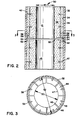
- Figure 2 is a sectional view through two sections of insulated conduit according to an embodiment of the invention, stacked one on top of the other
- Figure 3 is a sectional view taken on line 3-3 of Figure 2, with insulating material omitted for clarity.
- a conduit 30 to convey a high temperature particulate material therethrough is typically cylindrical in cross-section but other geometric cross-sections could be used.
- the conduit 30 comprises a pipe or shell 32 having an inner surface 34.
- the shell 32 is generally made of carbon steel.
- a layer of insulating fibre board 36 is placed on the inner surface 34 of the shell 32.
- the insulating fibre board 36 is made from a material according to ASTM C 612 Class 5 HT block so that it readily deforms when a load is applied to a surface thereof.
- ASTM C 612 Class 5 HT block One supplier of such a material is US Gypsum under the name K-FAC 19.
- An inner layer of dense erosion-resistant refractory 38 is applied inside of and on top of the layer of insulating fibre board 36, to provide an inner surface 40, 41 with an inside diameter defining a passage 41 through which high temperature material can be conveyed.
- the layer of dense refractory 38 is advantageously a fused silica product.
- One supplier of such a material is North American Refractories Company under the name HPV-SX. This material has good insulating properties for a dense refractory but it is chosen primarily for its shock resistance and erosion resistance properties.
- HPV-SX North American Refractories Company
- This material has good insulating properties for a dense refractory but it is chosen primarily for its shock resistance and erosion resistance properties.
- the layer of dense refractory 38 Upon heating, the layer of dense refractory 38 will expand, loading and compressing the layer of fibre board 36 between the layer of dense refractory 38 and the inner surface 34 of the shell 32.
- the deformable nature of the layer of insulating fibre board 36 allows these thermally induced applied loads simply to crush the layer of insulating fibre board 36, absorbing the thermally induced loading. As a result, the pressure loads actually applied to the inner surface 34 of the shell 32 are reduced to a neg
- annular shelf 44 is provided to support the layer of dense refractory 38 against the force of gravity.
- the anchors 42 are still used to manufacture the conduit 30, and to "key" the layer of dense refractory 38 together should cracks still develop therein due to thermal cycling.
- the annular shelf 44 allows the layer of dense refractory 38 to expand and contract during temperature cycles, without restraining movement thereof, thereby avoiding tensile stresses which could cause the layer of dense refractory 38 to fail.
- the annular shelf 44 comprises a plurality of separate annular segments 46 having a thickness t and a width w and separated from one another by expansion gaps 48.
- the annular segments 46 are generally made of stainless steel.
- the expansion gaps 48 are relatively equally spaced about the periphery of the annular shelf 44.
- An inner diameter 50 defined by the annular segments 46 is chosen to be slightly greater than that of the inner diameter 40 defining the passage through which the high temperature material is conveyed.
- the annular segments 46 act like an extended surface fin whose overall design temperature increases the closer the tip 47 of each annular segment 46 comes to the passage of the conduit 30.
- the tips 47 of the annular segments 46 covered by the layer of dense refractory 38, heat transfer to the annular segments 46 is reduced thereby lowering the design temperature of the annular segments 46.
- the temperature at the inner diameter 50 of the annular shelf 44 can be nearly 537.7 o C (1000 o F) while the temperature at an outside diameter 52 of the annular shelf 44 would be only about 176.6 o C (350 o F).
- This severe temperature differential would cause the annular shelf 44 to bend into a cone shape, much like a BELLEVILLE washer, were it not for the presence of the expansion gaps 48 which divide the annular shelf 44 into the plurality of annular segments 46. This bending would cause the layer of dense refractory 38 to move, applying a load to the anchors 42 which would cause cracking of the layer of dense refractory 38.
- the expansion gaps 48 prevent the aforementioned cone-shaped bending of the annular shelf 44.
- Shear lugs 54 welded or otherwise affixed to the inner surface 34 of the shell 32, transmit the load on the annular shelf 44, due to the weight of the layer of dense refractory 38 and layer of insulating fibre board 36, to the shell 32.
- the number of shear lugs 54 is determined by the load to be supported; the shear lugs are also generally made of carbon steel.
- a curved plate 56 is welded or otherwise affixed along the outer periphery at the outside diameter 52 of each of the annular segments 46. This creates an "L-shape" in cross section being formed by the curved plate 56 and each annular segment 46.
- annular segments 46 and curved plate 56 could be fabricated together as a single, one-piece member.
- Right angle clips 58 are welded to the inner surface 34 of the shell 32 above the curved plate 56, but they are not welded or affixed to the curved plate 56. The right angle clips 58 engage the curved plate 56, thereby transmitting the rotational load on each annular segment 46 to the shell 32, and are also generally made of carbon steel.
- the annular segments 46 rest in an unrestrained fashion upon the shear lugs 54, "tied” to the shell 32 with only one right angle clip 58 for each annular segment 46.
- the described construction allows for movement of the annular segments 46 horizontally/radially in an unrestrained fashion due to the thermally induced expansions, thus nearly eliminating any warping or unwanted movement of the annular segments 46.
- annular shelf 44 is divided into a plurality of annular segments 46, separated from one another by expansion gaps 48.
- the choice of the exact number of annular segments 46 is a function of several factors. While Figure 3 shows eight annular segments, fewer annular segments 46 can be employed, and in such a design each annular segment 46 will carry a larger proportional part of the weight of the layer of dense refractory 38.
- the thickness t of each radial segment 46 is set by calculations of the bending stress at the intersection of the curved plate 56 with each annular segment 46. It is generally preferred that the width w of each annular segment 46 be approximately three quarters of the thickness of the layer of dense refractory 38 that will be supported thereby.
- each annular segment 46 Since only one right angle clip 58 is preferred for each annular segment 46, providing fewer but larger annular segments 46 will require larger and stronger clips 58 to prevent rotation of each of the annular segments 46. This can only be done up to a point, since the rotational load is eventually transmitted to the wall of the shell 32 at the affixation point of each right angle clip 58 to the inner surface 34 of the shell 32. If the load on each annular segment 46 becomes too great, the transmitted load to the shell 32 will cause localised kinking or deformation of the wall of the shell 32. Additionally, using fewer annular segments 46 increases the possibility that they will deform into a cone-shape when subjected to the thermal heating cycles. This is unacceptable since it will tend to move the layer of dense refractory 38 causing the aforementioned destructive point/line loading of the anchors 42 onto the layer of dense refractory 38.
- the inner surface 41 at the inner diameter 40 of the dense refractory 38 was visually examined after each temperature cycle, and after the test series one of the fabricated sections was destructively examined. The results showed no cracking of the layer of dense refractory 38 due to expansion of the annular shelf 44, or due to point/line loading of the anchors 42 on the layer of dense refractory 38.
- the annular segments 46 of the annular shelf 44 showed no signs of warping or displacement even though there was a 177.7 o C to 537.7 o C (350 o F) to 1000 o F) temperature differential across the width w of the annular segments 46 combined with the gravity loading of the refractory mass thereon.
- the annular segments 46 remained perpendicular to the curved plates 56, expanding freely without inducing shear forces on the layer of dense refractory 38, and the anchors 42 were not loaded by bending forces. As a result, a nearly crack free layer of dense refractory 38 was preserved.
- a conduit of the invention can be easily modularised into sections of any convenient length, each section being stacked upon an adjacent section.
- An expansion joint 60 using a gasket preferably made of KAOWOOL or other similar material would be placed between each section and a girth weld 62 would secure one section to another.
- the present insulated pipe construction is for use in the conveying of high temperature material such as is encountered in fluidised bed combustion boilers
- the invention can be used in any application where a hot gaseous or fluid medium alone or in combination with high temperature particulate material is conveyed via an insulated conduit.
Landscapes
- Engineering & Computer Science (AREA)
- General Engineering & Computer Science (AREA)
- Mechanical Engineering (AREA)
- Thermal Insulation (AREA)
Applications Claiming Priority (2)
| Application Number | Priority Date | Filing Date | Title |
|---|---|---|---|
| US07/433,622 US5078182A (en) | 1989-11-07 | 1989-11-07 | Insulated pipe construction |
| US433622 | 1989-11-07 |
Publications (2)
| Publication Number | Publication Date |
|---|---|
| EP0441025A2 true EP0441025A2 (fr) | 1991-08-14 |
| EP0441025A3 EP0441025A3 (en) | 1991-10-23 |
Family
ID=23720873
Family Applications (1)
| Application Number | Title | Priority Date | Filing Date |
|---|---|---|---|
| EP19900309795 Ceased EP0441025A3 (en) | 1989-11-07 | 1990-09-07 | Conduit |
Country Status (7)
| Country | Link |
|---|---|
| US (1) | US5078182A (fr) |
| EP (1) | EP0441025A3 (fr) |
| JP (1) | JPH0833185B2 (fr) |
| CN (1) | CN1018383B (fr) |
| CA (1) | CA2020911C (fr) |
| TR (1) | TR26228A (fr) |
| ZA (1) | ZA904657B (fr) |
Cited By (1)
| Publication number | Priority date | Publication date | Assignee | Title |
|---|---|---|---|---|
| GB2483699A (en) * | 2010-09-17 | 2012-03-21 | Dave Wills | Pipe internal insulation |
Families Citing this family (13)
| Publication number | Priority date | Publication date | Assignee | Title |
|---|---|---|---|---|
| US5318076A (en) * | 1992-11-13 | 1994-06-07 | Bloom Engineering Company, Inc. | Protective refractory locking mechanism |
| DE19502788C1 (de) * | 1995-01-28 | 1996-09-05 | Metallgesellschaft Ag | Verfahren und Vorrichtung zum Ableiten eines heißen, Kohlenmonoxid enthaltenden Gasgemisches |
| US5948135A (en) * | 1998-05-12 | 1999-09-07 | Ppg Industries Ohio, Inc. | Bushing insulation and frame arrangement for making fiber glass |
| DE60119779T2 (de) * | 2000-12-22 | 2007-04-26 | Mitsui Babcock Energy Ltd. | Isoliertes verbundrohr |
| CN1160557C (zh) | 2001-09-03 | 2004-08-04 | 北京埃索特核电子机械有限公司 | 钴60γ射线源-碘化铯或钨酸镉阵列探测器集装箱检测设备 |
| CN102979994B (zh) * | 2012-11-30 | 2014-12-03 | 宁夏天纵泓光节能余热技术有限公司 | 矿热炉烟气保温管制作方法及矿热炉烟气保温管 |
| CN112041602B (zh) * | 2018-05-16 | 2022-05-17 | 三菱动力株式会社 | 配管部件、气化复合发电装置及配管部件的组装方法 |
| WO2020068750A1 (fr) | 2018-09-27 | 2020-04-02 | Corning Incorporated | Appareil modulaire de distribution de verre fondu |
| EP3856690A1 (fr) * | 2018-09-27 | 2021-08-04 | Corning Incorporated | Appareils de formation de verre comprenant des systèmes d'affinage modulaire du verre |
| KR102112197B1 (ko) * | 2019-10-08 | 2020-05-19 | (주)동인엔지니어링 | 저온배관용 단열장치 |
| CA3147504C (fr) * | 2021-02-03 | 2025-08-05 | Syncrude Canada Ltd. In Trust For The Owners Of The Syncrude Project As Such Owners Exist Now And In The Future | Tuyauterie comprenant un element d'ancrage pour resister au delaminage d'une doublure d'une chemise de tuyau |
| CN113418203B (zh) * | 2021-07-01 | 2022-05-31 | 上海机易电站设备有限公司 | 一种膜式内冷高温炉烟管道及制造方法 |
| CN113883502B (zh) * | 2021-11-10 | 2024-04-12 | 杭州智兴热电有限公司 | 循环流化床锅炉的保温机构 |
Family Cites Families (10)
| Publication number | Priority date | Publication date | Assignee | Title |
|---|---|---|---|---|
| US3781167A (en) * | 1972-11-29 | 1973-12-25 | Combustion Eng | No-weld refractory covering for water cooled pipes |
| US3859040A (en) * | 1973-10-11 | 1975-01-07 | Holcroft & Co | Recuperator for gas-fired radiant tube furnace |
| DE2733611C2 (de) * | 1977-07-26 | 1982-10-14 | Kernforschungsanlage Jülich GmbH, 5170 Jülich | Transportleitung mit keramischer Innenisolierung zur Führung heißer Fluide |
| JPS5430561A (en) * | 1977-08-10 | 1979-03-07 | Hitachi Ltd | Heat insulating structure against high temperature and high pressure gas |
| NO149887C (no) * | 1978-03-15 | 1987-05-06 | Superfos Glasuld As | Plateformet isolasjonselement og fremgangsmaate til dets fremstilling. |
| FR2472716A1 (fr) * | 1979-12-27 | 1981-07-03 | Spie Batignolles | Canalisation pour le transport de fluides chauds ou froids |
| US4363504A (en) * | 1980-01-04 | 1982-12-14 | Curtiss-Wright Corporation | High temperature lined conduits, elbows and tees |
| US4428730A (en) * | 1981-05-20 | 1984-01-31 | United States Steel Corporation | Insulation for a furnace member |
| JPS58191394A (ja) * | 1982-04-30 | 1983-11-08 | カ−チス−ライト・コ−ポレ−シヨン | ライナ−を施した高温用導管、エルボウ、テイ−及びその製造方法 |
| JPS5932713A (ja) * | 1982-08-13 | 1984-02-22 | Hitachi Ltd | ボイラの空気流量制御方法 |
-
1989
- 1989-11-07 US US07/433,622 patent/US5078182A/en not_active Expired - Fee Related
-
1990
- 1990-07-11 CA CA002020911A patent/CA2020911C/fr not_active Expired - Fee Related
- 1990-07-30 CN CN90106517A patent/CN1018383B/zh not_active Expired
- 1990-08-21 TR TR90/0719A patent/TR26228A/xx unknown
- 1990-09-07 EP EP19900309795 patent/EP0441025A3/en not_active Ceased
- 1990-11-06 JP JP2299102A patent/JPH0833185B2/ja not_active Expired - Lifetime
-
1991
- 1991-06-20 ZA ZA904657A patent/ZA904657B/xx unknown
Cited By (2)
| Publication number | Priority date | Publication date | Assignee | Title |
|---|---|---|---|---|
| GB2483699A (en) * | 2010-09-17 | 2012-03-21 | Dave Wills | Pipe internal insulation |
| GB2483699B (en) * | 2010-09-17 | 2013-11-06 | Dave Wills | Pipe insulation |
Also Published As
| Publication number | Publication date |
|---|---|
| CA2020911A1 (fr) | 1991-05-08 |
| CN1018383B (zh) | 1992-09-23 |
| ZA904657B (en) | 1992-08-26 |
| EP0441025A3 (en) | 1991-10-23 |
| JPH0833185B2 (ja) | 1996-03-29 |
| TR26228A (tr) | 1995-02-15 |
| CA2020911C (fr) | 1997-06-24 |
| JPH03163298A (ja) | 1991-07-15 |
| US5078182A (en) | 1992-01-07 |
| CN1051616A (zh) | 1991-05-22 |
Similar Documents
| Publication | Publication Date | Title |
|---|---|---|
| US5078182A (en) | Insulated pipe construction | |
| US4045056A (en) | Expansion compensator for pipelines | |
| US4961761A (en) | Cyclone separator wall refractory material system | |
| JPH0755385A (ja) | 高温熱交換器 | |
| US3607130A (en) | Reformer furnace | |
| EP3116976B1 (fr) | Revêtement interne de tambour d'unité de cokéfaction différée | |
| US4709643A (en) | Primary stage combustor lining | |
| US5775269A (en) | Boiler protection tube assembly | |
| WO1996032617A1 (fr) | Systeme d'echangeur de chaleur en ceramique | |
| US3984131A (en) | Packing gland for TiCl4 inlet to oxidizer reactor | |
| EP0032319B1 (fr) | Four avec joint réfractaire pour les extrémités de tubes saillants | |
| US4433722A (en) | Heat exchanger having pipe coils supported in support plates | |
| JP4381989B2 (ja) | 2重炎加熱処理炉 | |
| US4665950A (en) | Medium-carrying line having at least one restrictor | |
| JP3610561B2 (ja) | 高温配管のライニング構造 | |
| JPH0214953B2 (fr) | ||
| HU210401B (en) | Delivery conduit for hot granular material | |
| US4193355A (en) | Furnace walls which can be used at high temperatures | |
| US4408570A (en) | Tube hanger for steam generator | |
| EP0038204A1 (fr) | Ancrage métallique et support comprenant une surface métallique et une série d'ancrages réfractaires | |
| CA1184440A (fr) | Four a haute temperature | |
| US4287158A (en) | Support system for internal structure in a high temperature vessel | |
| Mcgannon | Burner Tile Testing for Deactivation Furnace Afterburner (AFB). | |
| JP6653186B2 (ja) | 耐火構造物 | |
| JPS6158516B2 (fr) |
Legal Events
| Date | Code | Title | Description |
|---|---|---|---|
| PUAI | Public reference made under article 153(3) epc to a published international application that has entered the european phase |
Free format text: ORIGINAL CODE: 0009012 |
|
| AK | Designated contracting states |
Kind code of ref document: A2 Designated state(s): ES IT SE |
|
| PUAL | Search report despatched |
Free format text: ORIGINAL CODE: 0009013 |
|
| AK | Designated contracting states |
Kind code of ref document: A3 Designated state(s): ES IT SE |
|
| 17P | Request for examination filed |
Effective date: 19920127 |
|
| 17Q | First examination report despatched |
Effective date: 19920414 |
|
| STAA | Information on the status of an ep patent application or granted ep patent |
Free format text: STATUS: THE APPLICATION HAS BEEN REFUSED |
|
| 18R | Application refused |
Effective date: 19930329 |