EP0441042A2 - Unter Druck stehender pulverförmiger Träger für ein Behandlungsverfahren - Google Patents
Unter Druck stehender pulverförmiger Träger für ein Behandlungsverfahren Download PDFInfo
- Publication number
- EP0441042A2 EP0441042A2 EP90313708A EP90313708A EP0441042A2 EP 0441042 A2 EP0441042 A2 EP 0441042A2 EP 90313708 A EP90313708 A EP 90313708A EP 90313708 A EP90313708 A EP 90313708A EP 0441042 A2 EP0441042 A2 EP 0441042A2
- Authority
- EP
- European Patent Office
- Prior art keywords
- support medium
- particulate support
- pressure
- container
- particulate
- Prior art date
- Legal status (The legal status is an assumption and is not a legal conclusion. Google has not performed a legal analysis and makes no representation as to the accuracy of the status listed.)
- Granted
Links
Images



Classifications
-
- F—MECHANICAL ENGINEERING; LIGHTING; HEATING; WEAPONS; BLASTING
- F27—FURNACES; KILNS; OVENS; RETORTS
- F27D—DETAILS OR ACCESSORIES OF FURNACES, KILNS, OVENS OR RETORTS, IN SO FAR AS THEY ARE OF KINDS OCCURRING IN MORE THAN ONE KIND OF FURNACE
- F27D5/00—Supports, screens or the like for the charge within the furnace
- F27D5/0068—Containers
-
- A—HUMAN NECESSITIES
- A61—MEDICAL OR VETERINARY SCIENCE; HYGIENE
- A61B—DIAGNOSIS; SURGERY; IDENTIFICATION
- A61B17/00—Surgical instruments, devices or methods
- A61B17/064—Surgical staples, i.e. penetrating the tissue
- A61B17/0643—Surgical staples, i.e. penetrating the tissue with separate closing member, e.g. for interlocking with staple
-
- B—PERFORMING OPERATIONS; TRANSPORTING
- B29—WORKING OF PLASTICS; WORKING OF SUBSTANCES IN A PLASTIC STATE IN GENERAL
- B29C—SHAPING OR JOINING OF PLASTICS; SHAPING OF MATERIAL IN A PLASTIC STATE, NOT OTHERWISE PROVIDED FOR; AFTER-TREATMENT OF THE SHAPED PRODUCTS, e.g. REPAIRING
- B29C43/00—Compression moulding, i.e. applying external pressure to flow the moulding material; Apparatus therefor
- B29C43/32—Component parts, details or accessories; Auxiliary operations
-
- B—PERFORMING OPERATIONS; TRANSPORTING
- B29—WORKING OF PLASTICS; WORKING OF SUBSTANCES IN A PLASTIC STATE IN GENERAL
- B29C—SHAPING OR JOINING OF PLASTICS; SHAPING OF MATERIAL IN A PLASTIC STATE, NOT OTHERWISE PROVIDED FOR; AFTER-TREATMENT OF THE SHAPED PRODUCTS, e.g. REPAIRING
- B29C71/00—After-treatment of articles without altering their shape; Apparatus therefor
- B29C71/02—Thermal after-treatment
-
- B—PERFORMING OPERATIONS; TRANSPORTING
- B29—WORKING OF PLASTICS; WORKING OF SUBSTANCES IN A PLASTIC STATE IN GENERAL
- B29L—INDEXING SCHEME ASSOCIATED WITH SUBCLASS B29C, RELATING TO PARTICULAR ARTICLES
- B29L2031/00—Other particular articles
- B29L2031/727—Fastening elements
-
- B—PERFORMING OPERATIONS; TRANSPORTING
- B29—WORKING OF PLASTICS; WORKING OF SUBSTANCES IN A PLASTIC STATE IN GENERAL
- B29L—INDEXING SCHEME ASSOCIATED WITH SUBCLASS B29C, RELATING TO PARTICULAR ARTICLES
- B29L2031/00—Other particular articles
- B29L2031/753—Medical equipment; Accessories therefor
- B29L2031/7546—Surgical equipment
-
- F—MECHANICAL ENGINEERING; LIGHTING; HEATING; WEAPONS; BLASTING
- F27—FURNACES; KILNS; OVENS; RETORTS
- F27D—DETAILS OR ACCESSORIES OF FURNACES, KILNS, OVENS OR RETORTS, IN SO FAR AS THEY ARE OF KINDS OCCURRING IN MORE THAN ONE KIND OF FURNACE
- F27D7/00—Forming, maintaining or circulating atmospheres in heating chambers
- F27D7/06—Forming or maintaining special atmospheres or vacuum within heating chambers
- F27D2007/066—Vacuum
Definitions
- This invention relates to supporting a fabricated piece for purposes of treating said fabricated piece and in particular to a method for supporting a thermoplastic piece for annealing.
- plastics are annealed to remove residual stresses and strains, to stabilize the shape of a plastic piece, and to reduce or eliminate defects in the piece.
- residual flow induced stresses may remain in the piece, as well as stresses from the differential density, shrinkage, and the viscoelastic behavior of the plastic during nonuniform cooling. Stresses are usually induced by quickly cooling a polymer from above its glass transition temperature. Molded thermoplastics containing residual stresses are more likely to develop stress crazing and stress cracking.
- plastic pieces are usually annealed. Annealing typically comprises reheating the plastic to above its glass transition temperature where chain mobility is greatest, and then slowly and gradually cooling the plastic to avoid reintroducing stresses. Plastic which is heated above its glass transition temperature usually relieves internal stresses by changes in density and specific volume.
- a freely held piece will often undergo distortion and shrinkage.
- Presently used equipment for annealing plastic usually comprises either liquid baths or hot air. Liquid bath methods using water, oil or waxes, usually make some provision for recycling the liquid to prevent temperature build-up or hot spots. Air flow methods usually employ circulating-air or air flow ovens. Other methods such as using convection ovens infrared ovens, and dielectric (e.g. microwave) ovens are also employed. Generally such methods require means such as racks or clamps to hold or suspend the plastic piece in the annealing oven.
- Plastic pieces used in surgical procedures often have complicated structures and must operate in conditions where close tolerances are required. Even small distortion or shrinkage in plastic pieces such as surgical fasteners is undesirable. Racks or simple clamping means are not effective for eliminating distortion or shrinkage, hence the use of fixturing, which involves supporting the plastic piece along substantially its entire external surface, usually by placing the plastic piece in a device closely resembling the mold from which the piece was originally fabricated. Pieces which have fine surface detail require expensive fixtures to match and support the detailed configuration of the piece.
- Annealing is but one example of various processes which require a work piece to be supported in this manner.
- Other treating processes which require access to the surface of the work piece such as those entailing chemical reactions, diffusion, coating, etc., often cannot be efficiently performed with the customary fixturing apparatus and methods.
- the present invention provides a novel and inexpensive method to support a work piece for undergoing treatment processes, such method providing support over substantially the entire surface of the work piece while allowing access to the surface for various treatment and conditioning processes.
- the invention further provides a unique method for supporting a work piece having at least one hollow or cut-out section either internally or externally so as to maintain an equilibrium between internal and external pressure forces applied to the work piece.
- the invention also provides a surgical fastener constructed of a material treated in accordance with the method disclosed herein.
- a method for supporting an object to be treated comprising placing the object within a particulate support medium, and compacting the support medium into a rigid mass by applying pressurizing means to create a difference between the pressure outside the particulate support medium and the pressure inside the particulate support medium.
- the pressurizing means can comprise reducing the pressure inside the support medium as, for example, by applying a vacuum to the interior of the support medium, preferably with an inside pressure of less than 1 torr.
- the support medium is optimally contained within a flexible container such as a flexible bag if application of a vacuum is the pressurizing means.
- the pressurizing means also can comprise increasing the pressure outside the particulate support medium such as by applying pressure to the particulate support medium by a piston means wherein the piston means is hydraulically driven, pneumatically driven, spring driven, or driven by deadweight.
- the particulate support medium is ideally contained in a rigid container if a piston means is employed.
- the object can then be treated by, for example, annealing the object.
- the particulate support medium can comprise powdered talc, or sodium bicarbonate, preferably sodium bicarbonate which has been conditioned by treating for about 12 hours at about 125°C, or any other suitable particulate material.
- An alternative embodiment provides a method for supporting an object for a treating process comprising placing the object within a particulate support material, enclosing the object and particulate support material within a rigid container which is sealed on all sides, the particulate support material and the container having different coefficients of thermal expansion, and compacting the particulate support medium by changing the temperature of the support medium and the container.
- the particulate support material has a coefficient of thermal expansion greater than that of the container
- changing the temperature is accomplished by heating the container and particulate support medium.
- the particulate support medium has a coefficient of thermal expansion less than that of the container, changing the temperature comprises cooling the container and particulate support medium.
- the method of the present invention utilizes a pressurizing means to compress a body of particulate support medium in which a piece to be treated is embedded.
- the work piece contemplated is any object on which it is desired to effect a treatment process.
- a preferred work piece is constructed of an annealable material such as molded thermoplastics, or the like.
- the application of the method of the present invention to bioabsorbable surgical fastener is contemplated.
- pressurized powder support of the present invention is particularly suitable for annealing, other methods of treatment which entail coating a work piece, diffusion of materials into or out of the work piece, chemical reactions with the work piece, etc. are also contemplated as being within the scope of the present invention.
- Pressurizing is defined as establishing a pressure difference such that the pressure external to the body of particulate medium is greater than the pressure internal to the body of particulate medium, thereby resulting in compression of the medium. Such pressurizing may be achieved by increasing the external pressure or by decreasing the internal pressure.
- Increasing the external pressure may be accomplished, for example, by a piston actuated by hydraulic or pneumatic means, by spring mechanism, or by a dead weight applied to the piston.
- Another way to increase the external pressure is by a pre-stressed membrane, i.e. for example placing the particulate medium in a pre-stretched elastic membrane and then allowing the membrane to contract.
- Decreasing the internal pressure may be accomplished by applying a vacuum to the interior of the particulate medium.
- a preferred method for the use of an evacuated powder support medium for treatment processes is described below.
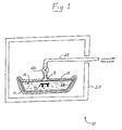
- thermoplastic work piece 12 to be annealed is embedded in a finely divided support medium 14 contained within a pan or receptacle 16.
- Work piece 12 may be of any shape or configuration and is generally produced from an injection molding process.
- the support medium 14 may be any inert powder of suitable particle size to rigidly support the piece. Because work piece 12 may be only a few millimeters in size, and of relatively complex shape, it is important that the particle size of powder 14 be sufficiently small relative to the work piece so as to enable the powder to conform to and to support the intricate surface detail of piece 12. Powdered talc has been found to be useful. However, it is preferable to employ a powder which is water soluble and can be washed free from the piece 12 after annealing.
- sodium bicarbonate has been found to be an effective support medium.
- the sodium bicarbonate powder is preferably conditioned by heating in an oven in flat pans at about 125°C for about 12 hours, whereby it is largely converted to the carbonate.
- the powder is then cooled and sifted through #20 standard mesh screen and stored dry.
- the particles of the support medium 14 are able to flow around work piece 12 and to conform to the details of the exterior surface of the piece.
- a fine mesh screen 19 is positioned above the layer of support medium 14 to prevent it from being drawn out by the vacuum.
- the pan 16 containing the support medium 14 and embedded piece 12 is placed into a flexible air tight vacuum bag 18.
- Vacuum bag 18 may completely envelop pan 16 although this is not essential, provided that a substantially airtight enclosure of support medium 14 is accomplished.
- the apparatus is placed in oven 20 and connected to a vacuum line 24 by means of valve 22, and a vacuum is applied to the interior of bag 18 to reduce the interior pressure preferably to about 1 torr.
- the application of a vacuum to bag 18 serves to create a pressure differential between the interior and exterior of bag 18.
- the external pressure is a standard atmosphere, i.e. 760 torr
- reducing the pressure within bag 18 through the application of a vacuum to 1 torr will create a pressure differential of almost one atmosphere.
- the maximum pressure differential obtainable by vacuum means alone is atmospheric pressure, or about one atmosphere.
- higher pressure differentials may be achieved by increasing the external atmospheric pressure, e.g. by placing bag 18 in a pressure oven.
- alternative methods i.e. increasing the pressure of the surrounding atmosphere, and decreasing the internal pressure
- the ability to adjust the pressure differential is a highly desirable feature since the work pieces to be treated or the treatment processes to be employed may have characteristics which require certain pressure differences or certain internal pressures.
- a vacuum bag sealer (not shown) may be used to maintain the vacuum within bag 18. After drawing the vacuum, bag 18 is sealed as a unit. Disposable plastic bags may be employed. Use of a vacuum bag sealer eliminates the need for the bag to be constantly attached to a vacuum source. When the interstitial air is evacuated the particles of the support medium 14 are compacted into a rigid mass for as long as the vacuum is maintained. Thus, the powder 14 which was once fluid is temporarily rigidified into an inflexible mold-like support which presents an inner surface conforming in exact detail to the shape of work piece 12.
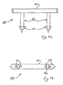
- a preferred application of the method of the present invention is directed to annealing surgical fasteners such as fastener 40 illustrated in Figs. 4a and 4b, and retainer portion 50 of a two part surgical fastener as illustrated in Figs. 2a and 2b.
- Such fasteners are often molded from thermoplastic materials which are bioabsorbable (i.e. absorbed by the human or animal body in which they are implanted). Because of the particularly sensitive environment and use contemplated by such fasteners, it is of utmost importance to anneal them to eliminate potential defects and stresses which would present unnecessary danger to patients.
- surgical fasteners are contemplated as a preferred application of the instant method, it is clearly applicable to all products constructed of thermoplastic materials where annealing is necessary or desirable.
- the powder support medium can fill the hollow spaces of the interior of a piece so that when the powder support medium is pressurized, the powder medium in the interior to the work piece is pressurized as much as the powder exterior to the work piece, thereby establishing a pressure equilibrium.
- Fig. 2a illustrates in plan view a retainer portion 50 of a two part surgical fastener, which is embedded in the powder support medium 14.
- Fig. 2b illustrates the retainer 50 in elevational partially sectional view. As can be seen the powder medium 14 enters and fills the hollow channel 52 extending through columnar members 51.
- retainer 50 is preferably oriented so that the opening 52a of hollow interior channel 52 is aligned with the inflow of powder medium 14, i.e. by being placed vertically upright. Powder 14 fills the channel 52 as it is being poured into container 16 and exerts pressure on the interior walls of the column to balance external pressure.
- oven 20 may be heated and held at a temperature and time sufficient to anneal the polymer.
- the appropriate temperature and heating time will depend upon the type of thermoplastic resin from which the plastic piece is constructed, the size and shape of the piece, the heating characteristics of the apparatus and support medium, etc. Convection heating is generally used, but other types of heating such as dielectric heating, microwave heating, etc. may also be employed.
- the apparatus When the heating has been completed, the apparatus is allowed to cool slowly to ambient or room temperature.
- the contents of the pan 16 are removed and separated by, for example, sifting on a standard mesh screen to separate the plastic work piece 12 from the powder 14. If a water soluble powder is used, such as sodium bicarbonate, piece 12 can be quickly rinsed in water to remove any traces of powder, then vacuum dried to remove the water.
- a water soluble powder such as sodium bicarbonate
- Fig. 3 is a diagrammatic view of alternative ways to pressurize the support medium.
- the thermoplastic work pieces such as the aforementioned surgical fastener 40, and retainer 50, which are to be treated, are placed in particulate support medium 14 contained within a rigid container 16.
- support medium 14 is preferably fine powder, such as conditioned sodium bicarbonate or talc.
- Piston 28 presses downwardly upon the support medium 14 by means of an applied force F, which may be applied by hydraulic or pneumatic means, or by a spring means, or by dead weight.
- the preferred sequence of operation is as follows. A quantity of powder support medium such as conditioned sodium bicarbonate or talc is placed in a cylindrical container and tamped down with piston 28 to produce a flat reference surface. Thermoplastic pieces such as surgical fasteners and retainers are placed on this surface and additional powder is applied and tamped. Alternate layers of support medium and plastic pieces are gradually built-up. Finally the piston is pressed down on the upper surface of the last layer of medium and secured by clamping means. The treatment process such as annealing is then performed as described hereinabove.
- powder support medium such as conditioned sodium bicarbonate or talc
- Sodium bicarbonate (baking soda) was conditioned in an oven in flat pans at 125°C for 12 hours. After cooling, the powder was sifted through a #20 standard mesh screen and stored dry. An aluminum pan (7 in. ⁇ 11 in. ⁇ 1 in.) was partially filled with a layer of the conditioned sodium bicarbonate. Parts to be annealed were then pressed by hand into the conditioned sodium bicarbonate powder. Additional conditioned sodium bicarbonate was added to fill the pan and to fill the hollow and cut-out sections of the parts. A thin, finely porous material, namely a paper hairnet, was used to cover the pan to hold the powder in place while applying a vacuum.
- the pan was placed in a Fairprene rubberized vacuum bag (11 in. ⁇ 16 in. inside dimensions) equipped with a vacuum disconnect fitting. The open end of the bag was clamped tightly closed. The bag was then placed in a convection oven equipped with a vacuum line. The vacuum bag was connected to the vacuum line and evacuated (less than 1 Torr) and maintained under vacuum. The oven was heated to 100°C for three hours, which was a sufficient temperature and time to crystallize the polymer.
- the vacuum bag and its contents were allowed to cool to room temperature before removing the pan.
- the contents of the pan were sifted on a standard 18 mesh screen to separate the parts from the powder.
- the parts were quickly rinsed in water to remove any traces of powder and then placed in a vacuum oven at less than 1 Torr to remove residual water.
- the shrinkage associated with the prior known fixturing method of annealing is compared with the shrinkage associated with the pressurized powder method of the present invention.
- Each fastener 40 comprised a backspan 41 and two prongs 42 projecting from the backspan 41.
- the prongs 42 each had barbs 43 at their tips.
- X1 the average of the measured dimensions prior to annealing
- X2 the average of the measured dimensions after annealing
- the pressure differential is not established by having a higher pressure external to the medium. Rather, a pressure differential is established between the powder medium and the object to be treated.
- the embodiment exemplified in Fig. 5 utilizes a difference in the coefficient of thermal expansion between the material which the particulate support comprises, and the material from which the container is made. A difference in thermal expansion will cause compression of the particulate support medium when the apparatus is subjected to a temperature change.
- a powder medium 14 is tightly packed around a thermoplastic piece 12, and is contained in rigid container 16 which is sealed on all sides.
- Lid 30 and container 16, for example, may be coupled together by means of a threaded joint.
- the powder medium 14 occupies substantially all of the free space of the interior of the container. There is essentially no gap between the upper surface level of the powder medium 14 and the bottom surface 30a of the lid.
- the particulate medium will be compressed by placing the apparatus in a heating environment: the expanding particles are confined within a container which expands to a lesser degree.
- the particulate support medium will be compressed if the apparatus is cooled, the container contracting to a greater degree than that of the medium.
- the choice of materials therefore, must be chosen to conform to the temperature requirements of the treatment process to be undergone. If the piece is to be subjected to an annealing process, and, therefore, heated to the appropriate temperature, the thermal expansion of the particulate medium must be greater than that of the container. Heating the apparatus will then cause the particulate medium to expand within a confined space, thereby creating a compression force on all sides of the piece while the piece is being treated.
- the pressurized powder support of the present invention may be used for processes other than annealing plastic.
- the particles can be employed as a carrier for a coating material.
- Various agents may be mixed with the powder medium for diffusion into the surface of the supported piece.
- the pressurized powder medium may be used to support pieces to be case hardened.
- a number 20 standard mesh as referred to above has openings of about 0.841 mm and a number 18 standard mesh has openings of about 1.00 mm.
Landscapes
- Engineering & Computer Science (AREA)
- Health & Medical Sciences (AREA)
- Life Sciences & Earth Sciences (AREA)
- Mechanical Engineering (AREA)
- Surgery (AREA)
- Animal Behavior & Ethology (AREA)
- Public Health (AREA)
- Heart & Thoracic Surgery (AREA)
- Medical Informatics (AREA)
- Molecular Biology (AREA)
- Nuclear Medicine, Radiotherapy & Molecular Imaging (AREA)
- General Health & Medical Sciences (AREA)
- Biomedical Technology (AREA)
- Veterinary Medicine (AREA)
- Physics & Mathematics (AREA)
- Thermal Sciences (AREA)
- General Engineering & Computer Science (AREA)
- Processing And Handling Of Plastics And Other Materials For Molding In General (AREA)
- Materials For Medical Uses (AREA)
- Physical Or Chemical Processes And Apparatus (AREA)
Applications Claiming Priority (2)
| Application Number | Priority Date | Filing Date | Title |
|---|---|---|---|
| US45141689A | 1989-12-15 | 1989-12-15 | |
| US451416 | 1989-12-15 |
Publications (3)
| Publication Number | Publication Date |
|---|---|
| EP0441042A2 true EP0441042A2 (de) | 1991-08-14 |
| EP0441042A3 EP0441042A3 (en) | 1991-12-11 |
| EP0441042B1 EP0441042B1 (de) | 1996-03-13 |
Family
ID=23792110
Family Applications (1)
| Application Number | Title | Priority Date | Filing Date |
|---|---|---|---|
| EP19900313708 Expired - Lifetime EP0441042B1 (de) | 1989-12-15 | 1990-12-14 | Unter Druck stehender pulverförmiger Träger für ein Behandlungsverfahren |
Country Status (3)
| Country | Link |
|---|---|
| EP (1) | EP0441042B1 (de) |
| CA (1) | CA2031758C (de) |
| DE (1) | DE69025909T2 (de) |
Cited By (1)
| Publication number | Priority date | Publication date | Assignee | Title |
|---|---|---|---|---|
| US7344608B2 (en) | 2003-12-17 | 2008-03-18 | Rolls-Royce Plc | Method and apparatus for heat-treating an article and a fixture for use in the same |
Families Citing this family (1)
| Publication number | Priority date | Publication date | Assignee | Title |
|---|---|---|---|---|
| US20150174795A1 (en) * | 2011-11-16 | 2015-06-25 | Jsr Corporation | Molding apparatus and thermoplastic molded product manufacturing method |
Family Cites Families (12)
| Publication number | Priority date | Publication date | Assignee | Title |
|---|---|---|---|---|
| US1582233A (en) * | 1924-01-14 | 1926-04-27 | Carbox Corp | Carburizing box |
| US2021666A (en) * | 1933-10-05 | 1935-11-19 | Timken Axle Co Detroit | Heat treating apparatus |
| US2395675A (en) * | 1941-03-03 | 1946-02-26 | Brunswick Balke Collender Co | Method of hardening cast phenolic resin |
| US3249964A (en) * | 1963-09-09 | 1966-05-10 | Stackpole Carbon Co | Producing dense articles from powdered carbon and other materials |
| SE344010B (de) * | 1968-01-30 | 1972-03-27 | W Heynold | |
| US4264556A (en) * | 1979-08-27 | 1981-04-28 | Kaplesh Kumar | Thermal isostatic densifying method and apparatus |
| US4416266A (en) * | 1981-05-15 | 1983-11-22 | The United States Of America As Represented By The Administrator Of The National Aeronautics And Space Administration | Medical clip |
| AU8679382A (en) * | 1981-08-10 | 1983-02-17 | Ethicon Inc. | Polyolefin surgical device |
| DE3418110C2 (de) * | 1984-05-16 | 1986-04-03 | Dornier Gmbh, 7990 Friedrichshafen | Verfahren zur Herstellung von ausgesteiften, tragenden Strukturen aus faserverstärktem härtbaren Kunststoff |
| US4671280A (en) * | 1985-05-13 | 1987-06-09 | Ethicon, Inc. | Surgical fastening device and method for manufacture |
| US4724123A (en) * | 1987-02-09 | 1988-02-09 | The Dow Chemical Company | Plastic foam container for the densification of powder material |
| US4828639A (en) * | 1987-08-26 | 1989-05-09 | Lockheed Corporation | Elastomeric ball pressurizing method for adhesive bonding of assemblies |
-
1990
- 1990-12-07 CA CA 2031758 patent/CA2031758C/en not_active Expired - Lifetime
- 1990-12-14 EP EP19900313708 patent/EP0441042B1/de not_active Expired - Lifetime
- 1990-12-14 DE DE1990625909 patent/DE69025909T2/de not_active Expired - Lifetime
Cited By (2)
| Publication number | Priority date | Publication date | Assignee | Title |
|---|---|---|---|---|
| US7344608B2 (en) | 2003-12-17 | 2008-03-18 | Rolls-Royce Plc | Method and apparatus for heat-treating an article and a fixture for use in the same |
| US7718015B2 (en) | 2003-12-17 | 2010-05-18 | Rolls-Royce Plc | Method and apparatus for heat-treating an article and a fixture for use in the same |
Also Published As
| Publication number | Publication date |
|---|---|
| DE69025909T2 (de) | 1996-08-14 |
| CA2031758A1 (en) | 1991-06-16 |
| DE69025909D1 (de) | 1996-04-18 |
| EP0441042A3 (en) | 1991-12-11 |
| EP0441042B1 (de) | 1996-03-13 |
| CA2031758C (en) | 1995-10-17 |
Similar Documents
| Publication | Publication Date | Title |
|---|---|---|
| US5160677A (en) | Pressurized powder support for treating processes | |
| US5778968A (en) | Method for heating or cooling wafers | |
| DE19860611C1 (de) | Verfahren zur Herstellung von Formkörpern aus Polymer-Schaumpartikeln | |
| US5622669A (en) | Process and apparatus for the vulcanizing of tires | |
| NL8102008A (nl) | Inrichting en werkwijze voor het onder druk hervormen van produkten. | |
| US5296069A (en) | Process for manufacturing implants having coated surfaces | |
| AU612610B2 (en) | Method and apparatus for vacuum packaging | |
| US11148328B2 (en) | Method and apparatus to produce auxetic foam | |
| JPH07501765A (ja) | 3次元対象物の製造方法および装置 | |
| US5160678A (en) | Pressurized powder support for treating processes | |
| EP0441042B1 (de) | Unter Druck stehender pulverförmiger Träger für ein Behandlungsverfahren | |
| EP0282941B1 (de) | Verfahren zum Kristallisieren von thermoplastischem Material | |
| JP4642354B2 (ja) | 改良された生分解性発泡体および関連技術 | |
| US4344903A (en) | Method of making a cellular polymeric resin body in a self contained high-pressure mold form | |
| GR3017961T3 (en) | A process and device for processing plastic waste into blocks. | |
| CA2050509A1 (en) | Method and apparatus for making a vacuum-package filled with granular material | |
| JPH02126845A (ja) | レジン床義歯の製作方法及びその装置 | |
| DE59007058D1 (de) | Verfahren zum Tempern von kohlenstoffhaltigen Rohlingen. | |
| SU1073119A1 (ru) | Устройство дл отверждени деталей из полимерных композиционных материалов | |
| JPH0986912A (ja) | ガス吸着材料微粉末の成形方法と熱処理用治具 | |
| SU1606800A1 (ru) | Способ теплоизол ции сосудов | |
| JPH0852812A (ja) | 複合材加圧成形治具及び複合材成形体の製造方法 | |
| JPH02111617A (ja) | 沈降ケイ酸の調製方法、該ケイ酸からなる断熱材、成形体および該成形体の製造方法 | |
| NL1017062C2 (nl) | Inrichting, alsmede werkwijze voor het verkleinen van een lichaam dat tenminste uit samendrukbaar materiaal is vervaardigd. | |
| JPH0222122B2 (de) |
Legal Events
| Date | Code | Title | Description |
|---|---|---|---|
| PUAI | Public reference made under article 153(3) epc to a published international application that has entered the european phase |
Free format text: ORIGINAL CODE: 0009012 |
|
| AK | Designated contracting states |
Kind code of ref document: A2 Designated state(s): DE FR GB |
|
| PUAL | Search report despatched |
Free format text: ORIGINAL CODE: 0009013 |
|
| AK | Designated contracting states |
Kind code of ref document: A3 Designated state(s): DE FR GB |
|
| 17P | Request for examination filed |
Effective date: 19920427 |
|
| 17Q | First examination report despatched |
Effective date: 19930809 |
|
| GRAA | (expected) grant |
Free format text: ORIGINAL CODE: 0009210 |
|
| AK | Designated contracting states |
Kind code of ref document: B1 Designated state(s): DE FR GB |
|
| REF | Corresponds to: |
Ref document number: 69025909 Country of ref document: DE Date of ref document: 19960418 |
|
| ET | Fr: translation filed | ||
| PLBE | No opposition filed within time limit |
Free format text: ORIGINAL CODE: 0009261 |
|
| STAA | Information on the status of an ep patent application or granted ep patent |
Free format text: STATUS: NO OPPOSITION FILED WITHIN TIME LIMIT |
|
| 26N | No opposition filed | ||
| REG | Reference to a national code |
Ref country code: GB Ref legal event code: IF02 |
|
| PGFP | Annual fee paid to national office [announced via postgrant information from national office to epo] |
Ref country code: GB Payment date: 20091229 Year of fee payment: 20 Ref country code: FR Payment date: 20100106 Year of fee payment: 20 |
|
| PGFP | Annual fee paid to national office [announced via postgrant information from national office to epo] |
Ref country code: DE Payment date: 20091230 Year of fee payment: 20 |
|
| REG | Reference to a national code |
Ref country code: GB Ref legal event code: PE20 Expiry date: 20101213 |
|
| PG25 | Lapsed in a contracting state [announced via postgrant information from national office to epo] |
Ref country code: GB Free format text: LAPSE BECAUSE OF EXPIRATION OF PROTECTION Effective date: 20101213 |
|
| PG25 | Lapsed in a contracting state [announced via postgrant information from national office to epo] |
Ref country code: DE Free format text: LAPSE BECAUSE OF EXPIRATION OF PROTECTION Effective date: 20101214 |