EP0441072B1 - Projecteur à usage médical, plus particulièrement chirurgical - Google Patents
Projecteur à usage médical, plus particulièrement chirurgical Download PDFInfo
- Publication number
- EP0441072B1 EP0441072B1 EP90402961A EP90402961A EP0441072B1 EP 0441072 B1 EP0441072 B1 EP 0441072B1 EP 90402961 A EP90402961 A EP 90402961A EP 90402961 A EP90402961 A EP 90402961A EP 0441072 B1 EP0441072 B1 EP 0441072B1
- Authority
- EP
- European Patent Office
- Prior art keywords
- dome
- operating light
- light according
- flexible material
- pivot
- Prior art date
- Legal status (The legal status is an assumption and is not a legal conclusion. Google has not performed a legal analysis and makes no representation as to the accuracy of the status listed.)
- Expired - Lifetime
Links
Images

Classifications
-
- F—MECHANICAL ENGINEERING; LIGHTING; HEATING; WEAPONS; BLASTING
- F21—LIGHTING
- F21V—FUNCTIONAL FEATURES OR DETAILS OF LIGHTING DEVICES OR SYSTEMS THEREOF; STRUCTURAL COMBINATIONS OF LIGHTING DEVICES WITH OTHER ARTICLES, NOT OTHERWISE PROVIDED FOR
- F21V21/00—Supporting, suspending, or attaching arrangements for lighting devices; Hand grips
- F21V21/40—Hand grips
- F21V21/403—Hand grips for operation or dentist lamps
-
- F—MECHANICAL ENGINEERING; LIGHTING; HEATING; WEAPONS; BLASTING
- F21—LIGHTING
- F21V—FUNCTIONAL FEATURES OR DETAILS OF LIGHTING DEVICES OR SYSTEMS THEREOF; STRUCTURAL COMBINATIONS OF LIGHTING DEVICES WITH OTHER ARTICLES, NOT OTHERWISE PROVIDED FOR
- F21V15/00—Protecting lighting devices from damage
- F21V15/04—Resilient mountings, e.g. shock absorbers
-
- F—MECHANICAL ENGINEERING; LIGHTING; HEATING; WEAPONS; BLASTING
- F21—LIGHTING
- F21W—INDEXING SCHEME ASSOCIATED WITH SUBCLASSES F21K, F21L, F21S and F21V, RELATING TO USES OR APPLICATIONS OF LIGHTING DEVICES OR SYSTEMS
- F21W2131/00—Use or application of lighting devices or systems not provided for in codes F21W2102/00-F21W2121/00
- F21W2131/20—Lighting for medical use
- F21W2131/205—Lighting for medical use for operating theatres
-
- Y—GENERAL TAGGING OF NEW TECHNOLOGICAL DEVELOPMENTS; GENERAL TAGGING OF CROSS-SECTIONAL TECHNOLOGIES SPANNING OVER SEVERAL SECTIONS OF THE IPC; TECHNICAL SUBJECTS COVERED BY FORMER USPC CROSS-REFERENCE ART COLLECTIONS [XRACs] AND DIGESTS
- Y10—TECHNICAL SUBJECTS COVERED BY FORMER USPC
- Y10S—TECHNICAL SUBJECTS COVERED BY FORMER USPC CROSS-REFERENCE ART COLLECTIONS [XRACs] AND DIGESTS
- Y10S362/00—Illumination
- Y10S362/804—Surgical or dental spotlight
Definitions
- the present invention relates to a projector for medical use, more particularly surgical, of the type comprising an illuminating dome mounted at articulation around different axes of positioning and orientation and provided, on at least a portion of its widest peripheral contour, of '' a protective tube made of flexible material.
- a projector of this type is described in document FR-A-1,241,989.
- This kind of lighting equipment which overhangs the operating table is adapted to be operated by the surgeon or his operating aids, and this so as to permanently obtain satisfactory lighting of the operating field throughout an operation.
- the illuminating dome of the projector Because of its function, which is to illuminate an operating field, whatever the working position of the surgeon, the illuminating dome of the projector has a large diametrical dimension and, associated with different support arms articulated together, forms a system necessarily bulky.
- the illuminating dome is adapted to be moved by the operator at a height of the order of two meters above ground level, so that it can be, at any time, directly operated by the operator.
- the object of the invention is to facilitate the handling and the adjustment in position of the illuminating dome, without increasing its inertia.
- the protective rod made of flexible material has an internal recess forming a recess and is dimensioned so as to form a gripping member for an operator, for maneuvering the dome.
- the blocking means are controlled by a capacitive effect control circuit comprising sensors arranged in the central handle or a handling hoop.
- the object of the present invention is to make handling and adjustment of the dome position even easier, with an arrangement of low cost, compact, reliable and a great flexibility of use.
- the tube provides the functions of protection against shocks, handling and control of the locking means, by authorizing the use of electrical or pneumatic control means insensitive to the environmental conditions of an operating theater. and whatever the relative positioning of the dome and the operator.
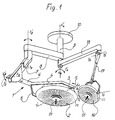
- an operating lighting installation 1 generally comprises a main illuminating dome 2 mounted for rotation F1 around a horizontal axis X1X'1, by a pair of diametrically opposite trunnions -one of which is visible in 3- mounted at the ends of two arms 4 and 5 integral with a fork 6.
- the fork 6 is mounted with articulation along F2 around an axis X2X'2 on an arm with substantially vertical extension 7, itself mounted for rotation along F3 around an axis X3X'3 on a support arm 8 with horizontal extension, which is articulated in rotation along F4 around a vertical axis X4X'4 on a tubular support 9 fixed to the ceiling of an operating room by a circular flange 10.
- annex projector with a dome 16 of more limited dimensions, mounted around an axis Y1Y'1 of a fork-shaped support mounted with articulation to rotate about an axis Y2Y'2 on an arm 17 itself mounted with articulation along the axis Y3Y'3 on an arm 10 articulated along F4 around the axis X4X'4 of the tubular support 9.
- each illuminating dome 2, 16, which has a wide lower edge, is equipped at its periphery with an impact protection flange 22 of flexible material, with an internal profile forming a shoulder annular top 24, an annular central latching groove 25 of the outer edge of the dome 2-16, and a wide annular groove 26 for retaining an optical plate 27.
- the external profile 28 of the protective flange 22 has a convex rounded shape of so as to ensure reception of any impact between the dome 2 (16) and a surrounding object and between the dome 2 and 16.
- This protective flange 22 is hollowed out to form an internal recess 29 to increase its flexibility and facilitate its assembly.
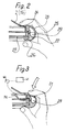
- the flange 22 is dimensioned transversely so as to constitute a gripping member which can be maneuvered by an operator as shown in FIGS. 2, 3 and 4. In this way, it is possible, by simple direct gripping of this flange 22, any desired re-orientation according to the axes X1X'1 (Y1Y'1), X2X'2 (Y2Y'2), X3X'3 (Y3Y'3) and even X4X'4, without requiring maneuvering hoops integral with the dome.
- the recess 29 forms an annular recess and the flexibility of the material constituting the tube 22 and the thickness of its wall 31 of external delimitation are adapted to allow crushing of the tube 22 by simple pressure between thumb and index finger. operator's hand.
- the effect of slight overpressure thus obtained is transferred by a thin tube 32 to a pressure detector 40, coupled to an articulation locking means 41 to ensure the unlocking or the resetting of usual brakes equipping the different articulation (s) (XX ') (YY').
- the signal transfer system of the pressure detector can ensure a permanent excitation of the electromagnets for releasing the articulation brakes during the entire overpressure phase, the disappearance of which causes the electromagnets to be put to rest and the relocking of the brakes, or indeed, the unlocking occurs during a first signal corresponding to a first so-called unlocking overpressure and this until the creation of a second so-called brake relocking overpressure.
- a control means with electrical contacts, for example in the form of two annular conductive pads 33 and 34 fixed at a small mutual spacing on the internal walls of the recess 29 to come into contact under the effect of a slight manual deformation of the flange 22.
- Each annular stud 33 (34) is connected by a conductor 35 (36) and a device transfer to the locking means 41 to provide the latter with a signal for controlling the unlocking-relocking of the articulation brakes.
- a handle 51 for central adjustment of fine adjustment of the illuminating dome 2 (16) is formed as a rigid sleeve 50 which is mounted on a tip protruding axially outward 52 of the support central dome 53 and defining an axial internal recess 54.
- the rigid sleeve 51 is secured in the mounted position by a pawl 63 articulated at 55 and subjected to a locking spring 56 and having an arm 57 whose lowering causes the escape of the ratchet 63.
- a flexible envelope 58 locking by engagement of an end bead 59 beyond a flange 60 of the rigid sleeve 51.
- the present invention applies to the lighting of operating tables, distribution systems in the operating room and intensive care and radiology devices.
Landscapes
- Engineering & Computer Science (AREA)
- General Engineering & Computer Science (AREA)
- Dental Tools And Instruments Or Auxiliary Dental Instruments (AREA)
- Surgical Instruments (AREA)
- Acyclic And Carbocyclic Compounds In Medicinal Compositions (AREA)
- Medicines Containing Antibodies Or Antigens For Use As Internal Diagnostic Agents (AREA)
- Non-Portable Lighting Devices Or Systems Thereof (AREA)
- Media Introduction/Drainage Providing Device (AREA)
- Pharmaceuticals Containing Other Organic And Inorganic Compounds (AREA)
Description
- La présente invention concerne un projecteur à usage médical, plus particulièrement chirurgical, du genre comportant une coupole éclairante montée à articulation autour de différents axes de positionnement et d'orientation et pourvue, sur au moins une portion de son contour périphérique le plus large, d'un boudin protecteur en matériau souple.
- Un projecteur de ce type est décrit dans le document FR-A-1.241.989. Ce genre de matériel d'éclairage qui surplombe la table opératoire est adapté à être manoeuvré par le chirurgien ou ses aides opératoires, et ce de façon à obtenir en permanence un éclairage satisfaisant du champ opératoire tout au long d'une opération. Du fait de sa fonction, qui est d'éclairer un champ opératoire, quelle que soit la position de travail du chirurgien, la coupole éclairante du projecteur a une dimension diamétrale importante et, associée à différents bras-supports articulés entre eux, forme un système nécessairement encombrant. La coupole éclairante est adaptée à être déplacée par l'opérateur à une hauteur de l'ordre de deux mètres au-dessus du niveau du sol, de façon à pouvoir être, à tout moment, directement manoeuvrée par l'opérateur.
- Dans le document ci-dessus, la manutention de la coupole s'effectue par une poignée au centre de l'optique.
- L'invention a pour objet de faciliter la manutention et le réglage en position de la coupole éclairante, sans augmenter son inertie.
- Pour ce faire, selon une caractéristique de l'invention, le boudin protecteur en matériau souple présente un évidement intérieur formant chambrage et est dimensionné de façon à former un organe de préhension pour un opérateur, pour manoeuvrer la coupole.
- Les projecteurs, notamment de grandes dimensions, sont pourvus aujourd'hui de moyens de blocage en position des articulations d'orientation, du type à frein à ressort et organe de blocage/déblocage, comme décrit dans le document FR-A-2.536.832. Dans ce document, les moyens de blocage sont commandés par un circuit de commande à effet capacitif comportant des capteurs disposés dans la poignée centrale ou un arceau de manipulation.
- La présente invention a pour objet de rendre encore plus aisée la manutention et le réglage en position de la coupole, avec un agencement de faible coût, compact, fiable et d'une grande souplesse d'utilisation.
- Pour ce faire, selon une autre caractéristique de l'invention, le chambrage est délimité, côté face extérieure du boudin par une paroi suffisamment mince pour être déformée par pression manuelle, et comporte des moyens de commande, sensibles à une déformation d'enfoncement local de ladite partie mince de paroi, pour commander le moyen de blocage d'articulation.
- Avec un tel agencement, le boudin assure les fonctions de protection contre les chocs, de manutention et de commande du moyen de blocage, en autorisant la mise en oeuvre de moyens de commande électriques ou pneumatiques insensibles aux conditions d'environnement d'un bloc opératoire et quel que soit le positionnement relatif de la coupole et de l'opérateur.
- D'autres caractéristiques et avantages de l'invention ressortiront de la description qui suit de modes de réalisation donnés à titre d'exemple, faite en référence avec les dessins annexés sur lesquels :
- la figure 1 est une vue en perspective d'une installation d'éclairage à projecteurs selon l'invention ;
- la figure 2 est une vue en coupe d'un détail de projecteur de la figure 1 ;
- les figures 3 et 4 sont des vues analogues à la figure 2 de deux variantes de réalisation ;
- la figure 5 est une vue en coupe d'une poignée de manoeuvre centrale de projecteur.
- En se référant aux figures 1 et 2, une installation d'éclairage opératoire 1 comprend généralement une coupole éclairante principale 2 montée à rotation F₁ autour d'un axe horizontal X₁X'₁, par une paire de tourillons diamétralement opposés -dont un est visible en 3- montés aux extrémités de deux bras 4 et 5 solidaires d'une fourche 6. La fourche 6 est montée à articulation selon F₂ autour d'un axe X₂X'₂ sur un bras à extension substantiellement verticale 7, lui-même monté à rotation selon F₃ autour d'un axe X₃X'₃ sur un bras-support 8 à extension horizontale, qui est articulé à rotation selon F₄ autour d'un axe vertical X₄X'₄ sur un support tubulaire 9 fixé au plafond d'une salle opératoire par une bride circulaire 10.
- Ainsi, la coupole 2 peut être orientée par rotation autour de l'axe X₁X'₁, rapprochée ou éloignée par rotation autour de l'axe X₂X'₂, et spatialement positionnée par rotation autour des axes X₃X'₃ et X₄X'₄.
- En pratique, on dispose au moins d'un projecteur annexe à coupole 16 de dimensions plus restreintes, montée autour d'un axe Y₁Y'₁ d'un support en forme de fourche montée à articulation à rotation autour d'un axe Y₂Y'₂ sur un bras 17 lui-même monté à articulation selon l'axe Y₃Y'₃ sur un bras 10 articulé selon F₄ autour de l'axe X₄X'₄ du support tubulaire 9.
- Comme on le voit mieux sur la figure 2, chaque coupole éclairante 2, 16, qui présente un large bord inférieur, est équipée à sa périphérie d'un boudin de protection contre les chocs 22 en matériau souple, avec un profil intérieur formant un épaulement annulaire haut 24, une gorge annulaire centrale d'encliquetage 25 du bord externe de coupole 2-16, et une large gorge annulaire 26 de retenue d'une plaque optique 27. Le profil extérieur 28 du boudin protecteur 22 a une forme arrondie convexe de façon à assurer la réception de tout choc entre la coupole 2 (16) et un objet environnant et entre les coupoles 2 et 16. Ce boudin protecteur 22 est évidé pour former un chambrage intérieur 29 pour accroître sa souplesse et faciliter son montage.
- Le boudin 22 est dimensionné transversalement de façon à constituer un organe de préhension manoeuvrable par un opérateur comme représenté aux figures 2, 3 et 4. De la sorte, on peut assurer par simple préhension directe de ce boudin 22, toute ré-orientation souhaitée selon les axes X₁X'₁ (Y₁Y'₁), X₂X'₂ (Y₂Y'₂), X₃X'₃ (Y₃Y'₃) et même X₄X'₄, sans nécessiter d'arceaux de manoeuvre solidaires de la coupole.
- Selon l'invention, l'évidement 29 forme un chambrage annulaire et la souplesse du matériau constituant le boudin 22 et l'épaisseur de sa paroi 31 de délimitation extérieure sont adaptées pour permettre un écrasement du boudin 22 par simple pression entre pouce et index de la main de l'opérateur. Dns le mode de réalisation de la figure 3, l'effet de légère surpression ainsi obtenu est transféré par un tube fin 32 vers un détecteur de pression 40, couplé à un moyen de blocage d'articulation 41 pour assurer le déblocage ou le reblocage de freins usuels équipant la ou les différentes articulations (XX') (YY'). Ces freins, de type connu, sont constitués d'une surface de friction solidaire d'un bras et adaptée à s'appuyer à ressort sur une surface de coopération solidaire d'un autre bras, et l'action de ressort peut être contrebalancée par un effet électromagnétique d'un aimant excité par un courant fourni sous commande d'un signal émis ici par le détecteur de pression 40.
- Ainsi, le système de transfert de signal du détecteur de pression peut assurer une excitation permanente des électroaimants de déblocage des freins d'articulation pendant toute la phase de surpression, dont la disparition provoque la mise au repos des électroaimants et le reblocage des freins, ou bien le déblocage se produit lors d'un premier signal correspondant à une première surpression dite de déblocage et cela jusqu'à la création d'une seconde surpression dite de reblocage des freins.
- Au lieu d'utiliser l'effet de surpression décrit ci-dessus, on peut, en variante, comme montré à la figure 4, mettre en oeuvre un moyen de commande à contacts électriques, par exemple sous forme de deux plots conducteurs annulaires 33 et 34 fixés à faible écartement mutuel sur les parois internes du chambrage 29 pour venir en contact sous l'effet d'une légère déformation manuelle du boudin 22. Chaque plot annulaire 33 (34) est raccordé par un conducteur 35 (36) et un dispositif de transfert au moyen de blocage 41 pour fournir à ce dernier un signal de commande du déblocage-reblocage des freins d'articulation.
- En se référant à la figure 5, une poignée 51 de manoeuvre centrale de réglage fin de la coupole éclairante 2 (16) est réalisée sous forme d'un manchon rigide 50 qui se monte sur un embout saillant axialement vers l'extérieur 52 du support central de coupole 53 et définissant un évidement intérieur axial 54. Le manchon rigide 51 est solidarisé en position montée par un cliquet 63 articulé en 55 et soumis à un ressort de verrouillage 56 et présentant un bras 57 dont l'abaissement provoque l'échappement du cliquet 63. Autour du manchon 51 est engagée une enveloppe souple 58 se verrouillant par un engagement d'un bourrelet d'extrémité 59 au delà d'un rebord 60 du manchon rigide 51. On réalise également ainsi un chambrage annulaire 61 communiquant par l'évidement 54 avec un tube 62 de liaison avec le détecteur de pression 40. La saisie de la poignée par le chirurgien provoque ainsi une surpression transférée au détecteur assurant, comme décrit précédemment, le déblocage des freins d'articulation des bras supports de coupole. A noter que la poignée est facilement amovible en vue de sa stérilisation.
- La présente invention s'applique à l'éclairage de tables opératoires, aux systèmes de distribution en salle d'opération et de soins intensifs et aux appareils de radiologie.
Claims (7)
- Projecteur à usage médical (1), plus particulièrement chirurgical, du genre comportant une coupole éclairante (2 ; 16) montée à articulation autour de différents axes de positionnement et d'orientation, et pourvue sur au moins une portion de son contour périphérique le plus large, d'un boudin protecteur en matériau souple (22), caractérisé en ce que le boudin protecteur en matériau souple (22) présente un évidement intérieur formant chambrage (29), et est dimensionné de façon à former un organe de préhension pour un opérateur pour manoeuvrer la coupole (2 ; 16).
- Projecteur selon la revendication 1, du genre où au moins une articulation d'orientation comprend un moyen de blocage d'articulation du type à frein à ressort et organe de blocage/déblocage, caractérisé en ce que le chambrage (29) est délimité, côté face extérieure du boudin (22) par une paroi suffisamment mince (31) pour être déformée par pression manuelle, et en ce qu'il comporte des moyens (32) (33, 36) de commande, sensibles à une déformation d'enfoncement local de ladite partie mince de paroi (31), pour commander le moyen de blocage d'articulation.
- Projecteur selon la revendication 2, caractérisé en ce que les moyens de commande comprennent un tube (32) de transfert de la pression interne de chambrage (29) vers un détecteur de pression du moyen de blocage d'articulation.
- Projecteur selon la revendication 2, caractérisé en ce que les moyens de commande comprennent deux plots en forme de couronnes (33 ; 34) à l'intérieur du chambrage (29), à faible écartement l'une de l'autre, dont l'une (33) est solidaire de ladite partie de paroi mince (31), raccordés électriquement (35 ; 36) au moyen de blocage d'articulation.
- Projecteur selon l'une des revendications précédentes caractérisé en ce que le boudin protecteur en matériau souple (22) est pourvu, du côté de sa face intérieure, d'une gorge d'encliquetage (25) du bord périphérique de coupole (2) (6).
- Projecteur selon l'une des revendications précédentes, caractérisé en ce que le boudin protecteur en matériau souple (22) est pourvu, du côté de sa face intérieure, d'une seconde gorge (26) de retenue d'une plaque optique (27).
- Projecteur selon la revendication 3, caractérisé en ce qu'il comprend en outre une poignée de manoeuvre centrale (51) comportant une chambre annulaire déformable (61) communiquant avec le détecteur de pression.
Applications Claiming Priority (2)
| Application Number | Priority Date | Filing Date | Title |
|---|---|---|---|
| FR9001322A FR2657947B1 (fr) | 1990-02-06 | 1990-02-06 | Projecteur a usage medical, plus particulierement chirurgical. |
| FR9001322 | 1990-02-06 |
Publications (2)
| Publication Number | Publication Date |
|---|---|
| EP0441072A1 EP0441072A1 (fr) | 1991-08-14 |
| EP0441072B1 true EP0441072B1 (fr) | 1995-03-29 |
Family
ID=9393408
Family Applications (1)
| Application Number | Title | Priority Date | Filing Date |
|---|---|---|---|
| EP90402961A Expired - Lifetime EP0441072B1 (fr) | 1990-02-06 | 1990-10-22 | Projecteur à usage médical, plus particulièrement chirurgical |
Country Status (10)
| Country | Link |
|---|---|
| US (1) | US5165786A (fr) |
| EP (1) | EP0441072B1 (fr) |
| JP (1) | JP2500946B2 (fr) |
| AT (1) | ATE120530T1 (fr) |
| AU (1) | AU641976B2 (fr) |
| CA (1) | CA2035619A1 (fr) |
| DE (1) | DE69018240T2 (fr) |
| FR (1) | FR2657947B1 (fr) |
| NO (1) | NO910406L (fr) |
| PT (1) | PT96673A (fr) |
Families Citing this family (30)
| Publication number | Priority date | Publication date | Assignee | Title |
|---|---|---|---|---|
| DE4338977C2 (de) * | 1993-11-15 | 1999-06-17 | Delma Elektro Med App | Leuchte für medizinischen Einsatz |
| DE19625411C2 (de) * | 1996-06-25 | 2002-07-04 | Siemens Ag | Medizinische Anlage mit verstellbarem Handgriff |
| US6132062A (en) * | 1998-03-27 | 2000-10-17 | Hill-Rom, Inc. | Task light for a surgical light apparatus |
| US6176597B1 (en) | 1998-03-27 | 2001-01-23 | Hill-Rom, Inc. | Reflector for surgical light apparatus |
| US6402351B1 (en) * | 1998-03-27 | 2002-06-11 | Hill-Rom Services, Inc., | Controls for a surgical light apparatus |
| USD421507S (en) * | 1998-03-30 | 2000-03-07 | Hill-Rom, Inc. | Surgical lighthead cover |
| USD437957S1 (en) | 1998-03-30 | 2001-02-20 | Hill-Rom, Inc. | Surgical light apparatus |
| USD421148S (en) * | 1998-03-30 | 2000-02-22 | Hill-Rom, Inc. | Handle for surgical headlight |
| DE19839827B4 (de) * | 1998-09-01 | 2007-12-20 | Ulrich Dr. Matern | Beleuchtungssystem für einen Operationsraum zum individuellen und automatischen Ausleuchten von Operationsbereichen sowie Verfahren hierzu |
| AU2597501A (en) * | 1999-12-23 | 2001-07-03 | Hill-Rom Services, Inc. | Surgical theater system |
| DE29923014U1 (de) * | 1999-12-30 | 2001-06-07 | HTI Entwicklungsgesellschaft mbH, 85560 Ebersberg | Operationsleuchte |
| FR2820971A1 (fr) | 2001-02-22 | 2002-08-23 | Alm | Dispositif de manutention d'un equipement medical supporte par une structure articulee |
| US7097145B2 (en) * | 2001-09-14 | 2006-08-29 | Hill-Rom Services, Inc. | Support arm for a surgical theater system |
| WO2003058115A1 (fr) * | 2002-01-07 | 2003-07-17 | Mehmet Ergin Karadag | Appareil d'eclairage a deux tetes lumineuses pour sieges de dentistes |
| EP1478877B1 (fr) | 2002-02-25 | 2006-04-19 | Steris Inc. | Systeme d'eclairage ambiant destine a des lampes chirurgicales |
| KR100602515B1 (ko) * | 2002-02-25 | 2006-07-19 | 스테리스 인코퍼레이티드 | 외과용 조명 시스템의 인체공학적 제어기 |
| DK1478876T3 (da) * | 2002-02-25 | 2006-02-13 | Steris Inc | Kirurgisk ophangssystem |
| US20050242261A1 (en) * | 2002-02-25 | 2005-11-03 | Steris Inc | Surgical suspension system |
| US8070322B2 (en) * | 2008-09-11 | 2011-12-06 | Dental Equipment, Llc | Examination light with readily accessible controls |
| JP5276550B2 (ja) * | 2009-08-19 | 2013-08-28 | 株式会社長田中央研究所 | 歯科用無影灯 |
| USD622897S1 (en) * | 2009-11-10 | 2010-08-31 | Dental Equipment, Llc | Dental examination light reflector |
| DE102010034562B8 (de) * | 2010-08-17 | 2017-08-31 | Drägerwerk AG & Co. KGaA | Operationsleuchte mit verbesserter Bedienungsfunktionalität |
| US20130001180A1 (en) * | 2011-06-29 | 2013-01-03 | Stout Christopher A | Sterile rack for contraceptive procedure |
| USD887624S1 (en) * | 2018-01-08 | 2020-06-16 | American Sterilizer Company | Camera handle for a surgical lighthead |
| USD894468S1 (en) * | 2018-01-10 | 2020-08-25 | American Sterilizer Company | Control handle for a surgical lighthead |
| USD893093S1 (en) * | 2018-02-05 | 2020-08-11 | American Sterilizer Company | Lighthead |
| EP4071406A1 (fr) | 2021-04-09 | 2022-10-12 | TRUMPF Medizin Systeme GmbH + Co. KG | Étrier pour un système de suspension d'une lampe médicale, système de suspension et système comprenant un corps de lampe médicale et un système de suspension |
| USD1014832S1 (en) | 2021-09-16 | 2024-02-13 | Trumpf Medizin Systeme Gmbh + Co. Kg | Support arm for a suspension apparatus for a medical lamp |
| USD1015622S1 (en) | 2021-09-16 | 2024-02-20 | Trumpf Medizin Systeme Gmbh + Co. Kg | Suspension apparatus for a medical lamp |
| GB2612018B (en) | 2021-09-20 | 2024-12-11 | Thomas Andrew | Adjustable support |
Family Cites Families (14)
| Publication number | Priority date | Publication date | Assignee | Title |
|---|---|---|---|---|
| US2911519A (en) * | 1956-09-18 | 1959-11-03 | Rodney Perdew | Remote controlled hospital light |
| US3005087A (en) * | 1958-07-28 | 1961-10-17 | Michael R Klein | Variable focusing, multi-beam, illuminating device |
| US3075071A (en) * | 1958-09-04 | 1963-01-22 | Ritter Co Inc | Sterilizable focusing means for surgical lights |
| FR1241989A (fr) * | 1959-11-17 | 1960-09-23 | Ritter Co Inc | Dispositifs stérilisables de focalisation pour lampes chirurgicales |
| FR1341061A (fr) * | 1962-11-20 | 1963-10-25 | Quarzlampen Gmbh | Scialytique à bras articulés |
| IT7653462U1 (it) * | 1976-09-07 | 1978-03-07 | Elma Spa | Proiettore fendinebbia atto ad essere montato in posizione frontale su di un autoveicolo |
| US4316238A (en) * | 1979-11-19 | 1982-02-16 | Kidde Consumer Durables Corp. | Light fixture and elevator therefor |
| DE3243709C3 (de) * | 1982-11-25 | 1994-12-15 | Delma Elektro Med App | Operationsleuchte |
| US4538214A (en) * | 1983-12-29 | 1985-08-27 | American Sterilizer Company | Magnetically supported surgical light |
| JPH0310735Y2 (fr) * | 1985-05-20 | 1991-03-18 | ||
| JPH048561Y2 (fr) * | 1987-02-16 | 1992-03-04 | ||
| US4801815A (en) * | 1987-11-12 | 1989-01-31 | The Boc Group, Inc. | Autostop mechanism for pendant assembly |
| JPH01135601U (fr) * | 1988-03-09 | 1989-09-18 | ||
| JPH01155415U (fr) * | 1988-04-15 | 1989-10-25 |
-
1990
- 1990-02-06 FR FR9001322A patent/FR2657947B1/fr not_active Expired - Fee Related
- 1990-10-22 AT AT90402961T patent/ATE120530T1/de not_active IP Right Cessation
- 1990-10-22 EP EP90402961A patent/EP0441072B1/fr not_active Expired - Lifetime
- 1990-10-22 DE DE69018240T patent/DE69018240T2/de not_active Expired - Fee Related
- 1990-11-05 US US07/608,774 patent/US5165786A/en not_active Expired - Fee Related
-
1991
- 1991-01-11 JP JP3001937A patent/JP2500946B2/ja not_active Expired - Lifetime
- 1991-02-04 CA CA002035619A patent/CA2035619A1/fr not_active Abandoned
- 1991-02-04 NO NO91910406A patent/NO910406L/no unknown
- 1991-02-05 PT PT96673A patent/PT96673A/pt not_active Application Discontinuation
- 1991-02-05 AU AU70256/91A patent/AU641976B2/en not_active Ceased
Also Published As
| Publication number | Publication date |
|---|---|
| PT96673A (pt) | 1992-10-30 |
| NO910406L (no) | 1991-08-07 |
| JP2500946B2 (ja) | 1996-05-29 |
| EP0441072A1 (fr) | 1991-08-14 |
| FR2657947B1 (fr) | 1994-04-29 |
| AU7025691A (en) | 1991-08-08 |
| JPH05305099A (ja) | 1993-11-19 |
| DE69018240T2 (de) | 1995-09-14 |
| NO910406D0 (no) | 1991-02-04 |
| FR2657947A1 (fr) | 1991-08-09 |
| US5165786A (en) | 1992-11-24 |
| AU641976B2 (en) | 1993-10-07 |
| CA2035619A1 (fr) | 1991-08-07 |
| DE69018240D1 (de) | 1995-05-04 |
| ATE120530T1 (de) | 1995-04-15 |
Similar Documents
| Publication | Publication Date | Title |
|---|---|---|
| EP0441072B1 (fr) | Projecteur à usage médical, plus particulièrement chirurgical | |
| EP1409878B1 (fr) | Dispositif de blocage de deux elements allonges telescopiques | |
| EP0549450A1 (fr) | Ensemble porte-gant pour une enceinte de confinement | |
| EP3042702A1 (fr) | Robot roulant et sauteur à capacité accrue de franchissement d'obstacles | |
| FR2773890A1 (fr) | Ensemble integre et compact de montage isostatique et de correction de position d'un organe, tel qu'un miroir, d'un telescope spatial | |
| USD408267S (en) | Tie-down bracket | |
| EP1321080A2 (fr) | Couvercle pour appareil de cuisson sous pression à mâchoires allégées et appareil de cuisson comportant un tel couvercle | |
| EP1747567A1 (fr) | Bouton rotatif pour circuit electrique | |
| EP3109878A1 (fr) | Ampoule à vide et appareillage de protection électrique comportant une telle ampoule | |
| BE1011613A3 (fr) | Niveau a bulle d'air. | |
| FR2696999A1 (fr) | Dispositif d'identification et de verrouillage d'une bouteille. | |
| USD450042S1 (en) | Aerial storage unit for fiber optic cable | |
| EP0394139A1 (fr) | Raccord intermédiaire pour embout d'appareil respiratoire | |
| FR2763925A1 (fr) | Dispositif de deplacement de charge | |
| FR2625847A1 (fr) | Dispositif de connexion magnetique entre une ampoule et sa douille | |
| FR2574588A1 (fr) | " manche a balai " | |
| EP1378621B1 (fr) | Mécanisme d'embrayage pour la commande d'une serrure, et porte le comportant | |
| USD455392S1 (en) | Aircraft wheel bearing hub seal protector | |
| USD459377S1 (en) | Handle for a magnifying glass | |
| BE1014293A3 (fr) | Mecanisme a couvercle articule pour dispositifs electriques. | |
| EP3925736A1 (fr) | Outil de manipulation a distance pour eviter une contamination | |
| FR2796707A1 (fr) | Eclairage operatoire a poignee de manutention a usage unique | |
| USD414441S (en) | Scepter linemarker | |
| EP0375528A1 (fr) | Dispositif de manipulation d'un miroir réfléchissant la lumière | |
| EP0987977A1 (fr) | Enrouleur pour aspirateur |
Legal Events
| Date | Code | Title | Description |
|---|---|---|---|
| PUAI | Public reference made under article 153(3) epc to a published international application that has entered the european phase |
Free format text: ORIGINAL CODE: 0009012 |
|
| 17P | Request for examination filed |
Effective date: 19901025 |
|
| AK | Designated contracting states |
Kind code of ref document: A1 Designated state(s): AT BE CH DE DK ES FR GB IT LI LU NL SE |
|
| 17Q | First examination report despatched |
Effective date: 19930323 |
|
| GRAA | (expected) grant |
Free format text: ORIGINAL CODE: 0009210 |
|
| AK | Designated contracting states |
Kind code of ref document: B1 Designated state(s): AT BE CH DE DK ES FR GB IT LI LU NL SE |
|
| PG25 | Lapsed in a contracting state [announced via postgrant information from national office to epo] |
Ref country code: NL Free format text: LAPSE BECAUSE OF NON-PAYMENT OF DUE FEES Effective date: 19950329 Ref country code: IT Free format text: LAPSE BECAUSE OF FAILURE TO SUBMIT A TRANSLATION OF THE DESCRIPTION OR TO PAY THE FEE WITHIN THE PRE;WARNING: LAPSES OF ITALIAN PATENTS WITH EFFECTIVE DATE BEFORE 2007 MAY HAVE OCCURRED AT ANY TIME BEFORE 2007. THE CORRECT EFFECTIVE DATE MAY BE DIFFERENT FROM THE ONE RECORDED.SCRIBED TIME-LIMIT Effective date: 19950329 Ref country code: AT Effective date: 19950329 Ref country code: DK Effective date: 19950329 Ref country code: ES Free format text: THE PATENT HAS BEEN ANNULLED BY A DECISION OF A NATIONAL AUTHORITY Effective date: 19950329 |
|
| REF | Corresponds to: |
Ref document number: 120530 Country of ref document: AT Date of ref document: 19950415 Kind code of ref document: T |
|
| GBT | Gb: translation of ep patent filed (gb section 77(6)(a)/1977) |
Effective date: 19950324 |
|
| REF | Corresponds to: |
Ref document number: 69018240 Country of ref document: DE Date of ref document: 19950504 |
|
| NLV1 | Nl: lapsed or annulled due to failure to fulfill the requirements of art. 29p and 29m of the patents act | ||
| PG25 | Lapsed in a contracting state [announced via postgrant information from national office to epo] |
Ref country code: LI Effective date: 19951031 Ref country code: CH Effective date: 19951031 Ref country code: BE Effective date: 19951031 |
|
| PLBE | No opposition filed within time limit |
Free format text: ORIGINAL CODE: 0009261 |
|
| STAA | Information on the status of an ep patent application or granted ep patent |
Free format text: STATUS: NO OPPOSITION FILED WITHIN TIME LIMIT |
|
| 26N | No opposition filed | ||
| BERE | Be: lapsed |
Owner name: A L M Effective date: 19951031 |
|
| REG | Reference to a national code |
Ref country code: CH Ref legal event code: PL |
|
| PGFP | Annual fee paid to national office [announced via postgrant information from national office to epo] |
Ref country code: FR Payment date: 19960911 Year of fee payment: 7 |
|
| PGFP | Annual fee paid to national office [announced via postgrant information from national office to epo] |
Ref country code: GB Payment date: 19960920 Year of fee payment: 7 |
|
| PGFP | Annual fee paid to national office [announced via postgrant information from national office to epo] |
Ref country code: DE Payment date: 19960923 Year of fee payment: 7 |
|
| PGFP | Annual fee paid to national office [announced via postgrant information from national office to epo] |
Ref country code: SE Payment date: 19960924 Year of fee payment: 7 |
|
| PGFP | Annual fee paid to national office [announced via postgrant information from national office to epo] |
Ref country code: LU Payment date: 19961001 Year of fee payment: 7 |
|
| PG25 | Lapsed in a contracting state [announced via postgrant information from national office to epo] |
Ref country code: GB Free format text: LAPSE BECAUSE OF NON-PAYMENT OF DUE FEES Effective date: 19971022 Ref country code: LU Free format text: LAPSE BECAUSE OF NON-PAYMENT OF DUE FEES Effective date: 19971022 |
|
| PG25 | Lapsed in a contracting state [announced via postgrant information from national office to epo] |
Ref country code: SE Free format text: LAPSE BECAUSE OF NON-PAYMENT OF DUE FEES Effective date: 19971023 |
|
| PG25 | Lapsed in a contracting state [announced via postgrant information from national office to epo] |
Ref country code: FR Free format text: THE PATENT HAS BEEN ANNULLED BY A DECISION OF A NATIONAL AUTHORITY Effective date: 19971031 |
|
| GBPC | Gb: european patent ceased through non-payment of renewal fee |
Effective date: 19971022 |
|
| PG25 | Lapsed in a contracting state [announced via postgrant information from national office to epo] |
Ref country code: DE Free format text: LAPSE BECAUSE OF NON-PAYMENT OF DUE FEES Effective date: 19980701 |
|
| EUG | Se: european patent has lapsed |
Ref document number: 90402961.8 |
|
| REG | Reference to a national code |
Ref country code: FR Ref legal event code: ST |