EP0441072B1 - Medizinischer Projektor, insbesondere für chirurgische Zwecke - Google Patents
Medizinischer Projektor, insbesondere für chirurgische Zwecke Download PDFInfo
- Publication number
- EP0441072B1 EP0441072B1 EP90402961A EP90402961A EP0441072B1 EP 0441072 B1 EP0441072 B1 EP 0441072B1 EP 90402961 A EP90402961 A EP 90402961A EP 90402961 A EP90402961 A EP 90402961A EP 0441072 B1 EP0441072 B1 EP 0441072B1
- Authority
- EP
- European Patent Office
- Prior art keywords
- dome
- operating light
- light according
- flexible material
- pivot
- Prior art date
- Legal status (The legal status is an assumption and is not a legal conclusion. Google has not performed a legal analysis and makes no representation as to the accuracy of the status listed.)
- Expired - Lifetime
Links
Images

Classifications
-
- F—MECHANICAL ENGINEERING; LIGHTING; HEATING; WEAPONS; BLASTING
- F21—LIGHTING
- F21V—FUNCTIONAL FEATURES OR DETAILS OF LIGHTING DEVICES OR SYSTEMS THEREOF; STRUCTURAL COMBINATIONS OF LIGHTING DEVICES WITH OTHER ARTICLES, NOT OTHERWISE PROVIDED FOR
- F21V21/00—Supporting, suspending, or attaching arrangements for lighting devices; Hand grips
- F21V21/40—Hand grips
- F21V21/403—Hand grips for operation or dentist lamps
-
- F—MECHANICAL ENGINEERING; LIGHTING; HEATING; WEAPONS; BLASTING
- F21—LIGHTING
- F21V—FUNCTIONAL FEATURES OR DETAILS OF LIGHTING DEVICES OR SYSTEMS THEREOF; STRUCTURAL COMBINATIONS OF LIGHTING DEVICES WITH OTHER ARTICLES, NOT OTHERWISE PROVIDED FOR
- F21V15/00—Protecting lighting devices from damage
- F21V15/04—Resilient mountings, e.g. shock absorbers
-
- F—MECHANICAL ENGINEERING; LIGHTING; HEATING; WEAPONS; BLASTING
- F21—LIGHTING
- F21W—INDEXING SCHEME ASSOCIATED WITH SUBCLASSES F21K, F21L, F21S and F21V, RELATING TO USES OR APPLICATIONS OF LIGHTING DEVICES OR SYSTEMS
- F21W2131/00—Use or application of lighting devices or systems not provided for in codes F21W2102/00-F21W2121/00
- F21W2131/20—Lighting for medical use
- F21W2131/205—Lighting for medical use for operating theatres
-
- Y—GENERAL TAGGING OF NEW TECHNOLOGICAL DEVELOPMENTS; GENERAL TAGGING OF CROSS-SECTIONAL TECHNOLOGIES SPANNING OVER SEVERAL SECTIONS OF THE IPC; TECHNICAL SUBJECTS COVERED BY FORMER USPC CROSS-REFERENCE ART COLLECTIONS [XRACs] AND DIGESTS
- Y10—TECHNICAL SUBJECTS COVERED BY FORMER USPC
- Y10S—TECHNICAL SUBJECTS COVERED BY FORMER USPC CROSS-REFERENCE ART COLLECTIONS [XRACs] AND DIGESTS
- Y10S362/00—Illumination
- Y10S362/804—Surgical or dental spotlight
Definitions
- the present invention relates to a projector for medical use, more particularly surgical, of the type comprising an illuminating dome mounted at articulation around different axes of positioning and orientation and provided, on at least a portion of its widest peripheral contour, of '' a protective tube made of flexible material.
- a projector of this type is described in document FR-A-1,241,989.
- This kind of lighting equipment which overhangs the operating table is adapted to be operated by the surgeon or his operating aids, and this so as to permanently obtain satisfactory lighting of the operating field throughout an operation.
- the illuminating dome of the projector Because of its function, which is to illuminate an operating field, whatever the working position of the surgeon, the illuminating dome of the projector has a large diametrical dimension and, associated with different support arms articulated together, forms a system necessarily bulky.
- the illuminating dome is adapted to be moved by the operator at a height of the order of two meters above ground level, so that it can be, at any time, directly operated by the operator.
- the object of the invention is to facilitate the handling and the adjustment in position of the illuminating dome, without increasing its inertia.
- the protective rod made of flexible material has an internal recess forming a recess and is dimensioned so as to form a gripping member for an operator, for maneuvering the dome.
- the blocking means are controlled by a capacitive effect control circuit comprising sensors arranged in the central handle or a handling hoop.
- the object of the present invention is to make handling and adjustment of the dome position even easier, with an arrangement of low cost, compact, reliable and a great flexibility of use.
- the tube provides the functions of protection against shocks, handling and control of the locking means, by authorizing the use of electrical or pneumatic control means insensitive to the environmental conditions of an operating theater. and whatever the relative positioning of the dome and the operator.
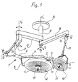
- an operating lighting installation 1 generally comprises a main illuminating dome 2 mounted for rotation F1 around a horizontal axis X1X'1, by a pair of diametrically opposite trunnions -one of which is visible in 3- mounted at the ends of two arms 4 and 5 integral with a fork 6.
- the fork 6 is mounted with articulation along F2 around an axis X2X'2 on an arm with substantially vertical extension 7, itself mounted for rotation along F3 around an axis X3X'3 on a support arm 8 with horizontal extension, which is articulated in rotation along F4 around a vertical axis X4X'4 on a tubular support 9 fixed to the ceiling of an operating room by a circular flange 10.
- annex projector with a dome 16 of more limited dimensions, mounted around an axis Y1Y'1 of a fork-shaped support mounted with articulation to rotate about an axis Y2Y'2 on an arm 17 itself mounted with articulation along the axis Y3Y'3 on an arm 10 articulated along F4 around the axis X4X'4 of the tubular support 9.
- each illuminating dome 2, 16, which has a wide lower edge, is equipped at its periphery with an impact protection flange 22 of flexible material, with an internal profile forming a shoulder annular top 24, an annular central latching groove 25 of the outer edge of the dome 2-16, and a wide annular groove 26 for retaining an optical plate 27.
- the external profile 28 of the protective flange 22 has a convex rounded shape of so as to ensure reception of any impact between the dome 2 (16) and a surrounding object and between the dome 2 and 16.
- This protective flange 22 is hollowed out to form an internal recess 29 to increase its flexibility and facilitate its assembly.
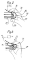
- the flange 22 is dimensioned transversely so as to constitute a gripping member which can be maneuvered by an operator as shown in FIGS. 2, 3 and 4. In this way, it is possible, by simple direct gripping of this flange 22, any desired re-orientation according to the axes X1X'1 (Y1Y'1), X2X'2 (Y2Y'2), X3X'3 (Y3Y'3) and even X4X'4, without requiring maneuvering hoops integral with the dome.
- the recess 29 forms an annular recess and the flexibility of the material constituting the tube 22 and the thickness of its wall 31 of external delimitation are adapted to allow crushing of the tube 22 by simple pressure between thumb and index finger. operator's hand.
- the effect of slight overpressure thus obtained is transferred by a thin tube 32 to a pressure detector 40, coupled to an articulation locking means 41 to ensure the unlocking or the resetting of usual brakes equipping the different articulation (s) (XX ') (YY').
- the signal transfer system of the pressure detector can ensure a permanent excitation of the electromagnets for releasing the articulation brakes during the entire overpressure phase, the disappearance of which causes the electromagnets to be put to rest and the relocking of the brakes, or indeed, the unlocking occurs during a first signal corresponding to a first so-called unlocking overpressure and this until the creation of a second so-called brake relocking overpressure.
- a control means with electrical contacts, for example in the form of two annular conductive pads 33 and 34 fixed at a small mutual spacing on the internal walls of the recess 29 to come into contact under the effect of a slight manual deformation of the flange 22.
- Each annular stud 33 (34) is connected by a conductor 35 (36) and a device transfer to the locking means 41 to provide the latter with a signal for controlling the unlocking-relocking of the articulation brakes.
- a handle 51 for central adjustment of fine adjustment of the illuminating dome 2 (16) is formed as a rigid sleeve 50 which is mounted on a tip protruding axially outward 52 of the support central dome 53 and defining an axial internal recess 54.
- the rigid sleeve 51 is secured in the mounted position by a pawl 63 articulated at 55 and subjected to a locking spring 56 and having an arm 57 whose lowering causes the escape of the ratchet 63.
- a flexible envelope 58 locking by engagement of an end bead 59 beyond a flange 60 of the rigid sleeve 51.
- the present invention applies to the lighting of operating tables, distribution systems in the operating room and intensive care and radiology devices.
Landscapes
- Engineering & Computer Science (AREA)
- General Engineering & Computer Science (AREA)
- Dental Tools And Instruments Or Auxiliary Dental Instruments (AREA)
- Surgical Instruments (AREA)
- Acyclic And Carbocyclic Compounds In Medicinal Compositions (AREA)
- Medicines Containing Antibodies Or Antigens For Use As Internal Diagnostic Agents (AREA)
- Non-Portable Lighting Devices Or Systems Thereof (AREA)
- Media Introduction/Drainage Providing Device (AREA)
- Pharmaceuticals Containing Other Organic And Inorganic Compounds (AREA)
Claims (7)
- Medizinischer Projektor (1), insbesondere für chirurgische Zwecke, welcher eine Beleuchtungskuppel (2; 16) aufweist, die um unterschiedliche Positionierungs- und Orientierungsachsen gelenkig gelagert ist und zumindest an einem Abschnitt ihres äußersten Randes mit einem Schutzkranz aus weichem Material (22) versehen ist, dadurch gekennzeichnet, daß der Schutzkranz aus weichem Material (22) einen eine Kammer (29) bildenden inneren Hohlraum hat und so dimensioniert ist, daß er ein Greiforgan für eine Bedienungsperson bildet, um die Kuppel (2; 16) zu bewegen.
- Projektor nach Anspruch 1, bei dem zumindest ein Orientierungsgelenk eine Gelenkverriegelungseinrichtung vom Federbremsentyp und ein Verriegelungs-Freigabeorgan aufweist, dadurch gekennzeichnet, daß die Kammer (29) auf der Seite der Außenfläche des Kranzes (22) durch eine Wand begrenzt ist, die ausreichend dünn (31) ist, um durch manuellen Druck verformt werden zu können, und daß sie Steuerungseinrichtungen (32) (33,36) enthält, die auf eine örtliche eindrückende Verformung des dünnen Teils der Wand (31) reagieren, um die Gelenkverriegelungseinrichtung zu steuern.
- Projektor nach Anspruch 2, dadurch gekennzeichnet, daß die Steuerungseinrichtungen eine Röhre (32) zur Übertragung des inneren Drucks der Kammer (29) zu einem Druckdetektor der Gelenkverriegelungseinrichtung aufweisen.
- Projektor nach Anspruch 2, dadurch gekennzeichnet, daß die Steuerungseinrichtungen zwei kronenförmige Steckstellen (33; 34) im Inneren der Kammer (29) aufweisen, die voneinander geringfügig beabstandet sind, wovon die eine (33) mit dem dünnen Teil der Wand (31) einstückig ist, und welche mit der Gelenkverriegelungseinrichtung elektrisch (35; 36) verbunden sind.
- Projektor nach einem der vorhergehenden Ansprüche, dadurch gekennzeichnet, daß der Schutzkranz (22) aus weichem Material an der Seite seiner Innenfläche mit einer Einrastkehle (25) für den Kuppelaußenrand (2) (6) versehen ist.
- Projektor nach einem der vorhergehenden Ansprüche, dadurch gekennzeichnet, daß der Schutzkranz (22) aus weichem Material auf der Seite seiner Innenfläche mit einer zweiten Haltekehle (26) für eine optische Platte (27) versehen ist.
- Projektor nach Anspruch 3, dadurch gekennzeichnet, daß er darüber hinaus einen mittigen Griff (51) zu seiner Bewegung aufweist, der eine verformbare, kreisringförmige Kammer (61) enthält, die mit dem Druckdetektor in Verbindung steht.
Applications Claiming Priority (2)
| Application Number | Priority Date | Filing Date | Title |
|---|---|---|---|
| FR9001322A FR2657947B1 (fr) | 1990-02-06 | 1990-02-06 | Projecteur a usage medical, plus particulierement chirurgical. |
| FR9001322 | 1990-02-06 |
Publications (2)
| Publication Number | Publication Date |
|---|---|
| EP0441072A1 EP0441072A1 (de) | 1991-08-14 |
| EP0441072B1 true EP0441072B1 (de) | 1995-03-29 |
Family
ID=9393408
Family Applications (1)
| Application Number | Title | Priority Date | Filing Date |
|---|---|---|---|
| EP90402961A Expired - Lifetime EP0441072B1 (de) | 1990-02-06 | 1990-10-22 | Medizinischer Projektor, insbesondere für chirurgische Zwecke |
Country Status (10)
| Country | Link |
|---|---|
| US (1) | US5165786A (de) |
| EP (1) | EP0441072B1 (de) |
| JP (1) | JP2500946B2 (de) |
| AT (1) | ATE120530T1 (de) |
| AU (1) | AU641976B2 (de) |
| CA (1) | CA2035619A1 (de) |
| DE (1) | DE69018240T2 (de) |
| FR (1) | FR2657947B1 (de) |
| NO (1) | NO910406L (de) |
| PT (1) | PT96673A (de) |
Families Citing this family (30)
| Publication number | Priority date | Publication date | Assignee | Title |
|---|---|---|---|---|
| DE4338977C2 (de) * | 1993-11-15 | 1999-06-17 | Delma Elektro Med App | Leuchte für medizinischen Einsatz |
| DE19625411C2 (de) * | 1996-06-25 | 2002-07-04 | Siemens Ag | Medizinische Anlage mit verstellbarem Handgriff |
| US6132062A (en) * | 1998-03-27 | 2000-10-17 | Hill-Rom, Inc. | Task light for a surgical light apparatus |
| US6176597B1 (en) | 1998-03-27 | 2001-01-23 | Hill-Rom, Inc. | Reflector for surgical light apparatus |
| US6402351B1 (en) * | 1998-03-27 | 2002-06-11 | Hill-Rom Services, Inc., | Controls for a surgical light apparatus |
| USD421507S (en) * | 1998-03-30 | 2000-03-07 | Hill-Rom, Inc. | Surgical lighthead cover |
| USD437957S1 (en) | 1998-03-30 | 2001-02-20 | Hill-Rom, Inc. | Surgical light apparatus |
| USD421148S (en) * | 1998-03-30 | 2000-02-22 | Hill-Rom, Inc. | Handle for surgical headlight |
| DE19839827B4 (de) * | 1998-09-01 | 2007-12-20 | Ulrich Dr. Matern | Beleuchtungssystem für einen Operationsraum zum individuellen und automatischen Ausleuchten von Operationsbereichen sowie Verfahren hierzu |
| AU2597501A (en) * | 1999-12-23 | 2001-07-03 | Hill-Rom Services, Inc. | Surgical theater system |
| DE29923014U1 (de) * | 1999-12-30 | 2001-06-07 | HTI Entwicklungsgesellschaft mbH, 85560 Ebersberg | Operationsleuchte |
| FR2820971A1 (fr) | 2001-02-22 | 2002-08-23 | Alm | Dispositif de manutention d'un equipement medical supporte par une structure articulee |
| US7097145B2 (en) * | 2001-09-14 | 2006-08-29 | Hill-Rom Services, Inc. | Support arm for a surgical theater system |
| WO2003058115A1 (en) * | 2002-01-07 | 2003-07-17 | Mehmet Ergin Karadag | Lighting device with two light heads for dental units |
| EP1478877B1 (de) | 2002-02-25 | 2006-04-19 | Steris Inc. | Umgebungsbeleuchtungssystem für operationsleuchte |
| KR100602515B1 (ko) * | 2002-02-25 | 2006-07-19 | 스테리스 인코퍼레이티드 | 외과용 조명 시스템의 인체공학적 제어기 |
| DK1478876T3 (da) * | 2002-02-25 | 2006-02-13 | Steris Inc | Kirurgisk ophangssystem |
| US20050242261A1 (en) * | 2002-02-25 | 2005-11-03 | Steris Inc | Surgical suspension system |
| US8070322B2 (en) * | 2008-09-11 | 2011-12-06 | Dental Equipment, Llc | Examination light with readily accessible controls |
| JP5276550B2 (ja) * | 2009-08-19 | 2013-08-28 | 株式会社長田中央研究所 | 歯科用無影灯 |
| USD622897S1 (en) * | 2009-11-10 | 2010-08-31 | Dental Equipment, Llc | Dental examination light reflector |
| DE102010034562B8 (de) * | 2010-08-17 | 2017-08-31 | Drägerwerk AG & Co. KGaA | Operationsleuchte mit verbesserter Bedienungsfunktionalität |
| US20130001180A1 (en) * | 2011-06-29 | 2013-01-03 | Stout Christopher A | Sterile rack for contraceptive procedure |
| USD887624S1 (en) * | 2018-01-08 | 2020-06-16 | American Sterilizer Company | Camera handle for a surgical lighthead |
| USD894468S1 (en) * | 2018-01-10 | 2020-08-25 | American Sterilizer Company | Control handle for a surgical lighthead |
| USD893093S1 (en) * | 2018-02-05 | 2020-08-11 | American Sterilizer Company | Lighthead |
| EP4071406A1 (de) | 2021-04-09 | 2022-10-12 | TRUMPF Medizin Systeme GmbH + Co. KG | Joch für ein aufhängungssystem für eine medizinische leuchte, aufhängungssystem und system eines medizinischen lampenkörpers und eines aufhängungssystems |
| USD1014832S1 (en) | 2021-09-16 | 2024-02-13 | Trumpf Medizin Systeme Gmbh + Co. Kg | Support arm for a suspension apparatus for a medical lamp |
| USD1015622S1 (en) | 2021-09-16 | 2024-02-20 | Trumpf Medizin Systeme Gmbh + Co. Kg | Suspension apparatus for a medical lamp |
| GB2612018B (en) | 2021-09-20 | 2024-12-11 | Thomas Andrew | Adjustable support |
Family Cites Families (14)
| Publication number | Priority date | Publication date | Assignee | Title |
|---|---|---|---|---|
| US2911519A (en) * | 1956-09-18 | 1959-11-03 | Rodney Perdew | Remote controlled hospital light |
| US3005087A (en) * | 1958-07-28 | 1961-10-17 | Michael R Klein | Variable focusing, multi-beam, illuminating device |
| US3075071A (en) * | 1958-09-04 | 1963-01-22 | Ritter Co Inc | Sterilizable focusing means for surgical lights |
| FR1241989A (fr) * | 1959-11-17 | 1960-09-23 | Ritter Co Inc | Dispositifs stérilisables de focalisation pour lampes chirurgicales |
| FR1341061A (fr) * | 1962-11-20 | 1963-10-25 | Quarzlampen Gmbh | Scialytique à bras articulés |
| IT7653462U1 (it) * | 1976-09-07 | 1978-03-07 | Elma Spa | Proiettore fendinebbia atto ad essere montato in posizione frontale su di un autoveicolo |
| US4316238A (en) * | 1979-11-19 | 1982-02-16 | Kidde Consumer Durables Corp. | Light fixture and elevator therefor |
| DE3243709C3 (de) * | 1982-11-25 | 1994-12-15 | Delma Elektro Med App | Operationsleuchte |
| US4538214A (en) * | 1983-12-29 | 1985-08-27 | American Sterilizer Company | Magnetically supported surgical light |
| JPH0310735Y2 (de) * | 1985-05-20 | 1991-03-18 | ||
| JPH048561Y2 (de) * | 1987-02-16 | 1992-03-04 | ||
| US4801815A (en) * | 1987-11-12 | 1989-01-31 | The Boc Group, Inc. | Autostop mechanism for pendant assembly |
| JPH01135601U (de) * | 1988-03-09 | 1989-09-18 | ||
| JPH01155415U (de) * | 1988-04-15 | 1989-10-25 |
-
1990
- 1990-02-06 FR FR9001322A patent/FR2657947B1/fr not_active Expired - Fee Related
- 1990-10-22 AT AT90402961T patent/ATE120530T1/de not_active IP Right Cessation
- 1990-10-22 EP EP90402961A patent/EP0441072B1/de not_active Expired - Lifetime
- 1990-10-22 DE DE69018240T patent/DE69018240T2/de not_active Expired - Fee Related
- 1990-11-05 US US07/608,774 patent/US5165786A/en not_active Expired - Fee Related
-
1991
- 1991-01-11 JP JP3001937A patent/JP2500946B2/ja not_active Expired - Lifetime
- 1991-02-04 CA CA002035619A patent/CA2035619A1/fr not_active Abandoned
- 1991-02-04 NO NO91910406A patent/NO910406L/no unknown
- 1991-02-05 PT PT96673A patent/PT96673A/pt not_active Application Discontinuation
- 1991-02-05 AU AU70256/91A patent/AU641976B2/en not_active Ceased
Also Published As
| Publication number | Publication date |
|---|---|
| PT96673A (pt) | 1992-10-30 |
| NO910406L (no) | 1991-08-07 |
| JP2500946B2 (ja) | 1996-05-29 |
| EP0441072A1 (de) | 1991-08-14 |
| FR2657947B1 (fr) | 1994-04-29 |
| AU7025691A (en) | 1991-08-08 |
| JPH05305099A (ja) | 1993-11-19 |
| DE69018240T2 (de) | 1995-09-14 |
| NO910406D0 (no) | 1991-02-04 |
| FR2657947A1 (fr) | 1991-08-09 |
| US5165786A (en) | 1992-11-24 |
| AU641976B2 (en) | 1993-10-07 |
| CA2035619A1 (fr) | 1991-08-07 |
| DE69018240D1 (de) | 1995-05-04 |
| ATE120530T1 (de) | 1995-04-15 |
Similar Documents
| Publication | Publication Date | Title |
|---|---|---|
| EP0441072B1 (de) | Medizinischer Projektor, insbesondere für chirurgische Zwecke | |
| EP1409878B1 (de) | Vorrichtung zur verriegelung zweier länglicher teleskopelemente | |
| EP0549450A1 (de) | Handschuhhalteeinrichtung für Isolierraum | |
| EP3042702A1 (de) | Roll- und springroboter mit erhöhter fähigkeit zur überwindung von hindernissen | |
| FR2773890A1 (fr) | Ensemble integre et compact de montage isostatique et de correction de position d'un organe, tel qu'un miroir, d'un telescope spatial | |
| USD408267S (en) | Tie-down bracket | |
| EP1321080A2 (de) | Dampfdruckkochtopfdeckel mit verkleinerten Klauen und Dampfdruckkochtopf mit einem solchen Deckel | |
| EP1747567A1 (de) | Drehknopf für ein elektrisches system | |
| EP3109878A1 (de) | Vakuumschalter und elektrische schutzgerät mit einer solchen vakuumschalter | |
| BE1011613A3 (fr) | Niveau a bulle d'air. | |
| FR2696999A1 (fr) | Dispositif d'identification et de verrouillage d'une bouteille. | |
| USD450042S1 (en) | Aerial storage unit for fiber optic cable | |
| EP0394139A1 (de) | Zwischenanschlussstück für den Atemgerätendstutzen | |
| FR2763925A1 (fr) | Dispositif de deplacement de charge | |
| FR2625847A1 (fr) | Dispositif de connexion magnetique entre une ampoule et sa douille | |
| FR2574588A1 (fr) | " manche a balai " | |
| EP1378621B1 (de) | Kupplungsmechanismus zum Betätigen eines Schlosses und eine damit ausgerüstete Tür | |
| USD455392S1 (en) | Aircraft wheel bearing hub seal protector | |
| USD459377S1 (en) | Handle for a magnifying glass | |
| BE1014293A3 (fr) | Mecanisme a couvercle articule pour dispositifs electriques. | |
| EP3925736A1 (de) | Fernbedienungswerkzeug zur vermeidung von kontamination | |
| FR2796707A1 (fr) | Eclairage operatoire a poignee de manutention a usage unique | |
| USD414441S (en) | Scepter linemarker | |
| EP0375528A1 (de) | Gerät zur Manipulierung eines lichtreflektierenden Spiegels | |
| EP0987977A1 (de) | Kabelaufrollvorrichtung für einen staubsauger |
Legal Events
| Date | Code | Title | Description |
|---|---|---|---|
| PUAI | Public reference made under article 153(3) epc to a published international application that has entered the european phase |
Free format text: ORIGINAL CODE: 0009012 |
|
| 17P | Request for examination filed |
Effective date: 19901025 |
|
| AK | Designated contracting states |
Kind code of ref document: A1 Designated state(s): AT BE CH DE DK ES FR GB IT LI LU NL SE |
|
| 17Q | First examination report despatched |
Effective date: 19930323 |
|
| GRAA | (expected) grant |
Free format text: ORIGINAL CODE: 0009210 |
|
| AK | Designated contracting states |
Kind code of ref document: B1 Designated state(s): AT BE CH DE DK ES FR GB IT LI LU NL SE |
|
| PG25 | Lapsed in a contracting state [announced via postgrant information from national office to epo] |
Ref country code: NL Free format text: LAPSE BECAUSE OF NON-PAYMENT OF DUE FEES Effective date: 19950329 Ref country code: IT Free format text: LAPSE BECAUSE OF FAILURE TO SUBMIT A TRANSLATION OF THE DESCRIPTION OR TO PAY THE FEE WITHIN THE PRE;WARNING: LAPSES OF ITALIAN PATENTS WITH EFFECTIVE DATE BEFORE 2007 MAY HAVE OCCURRED AT ANY TIME BEFORE 2007. THE CORRECT EFFECTIVE DATE MAY BE DIFFERENT FROM THE ONE RECORDED.SCRIBED TIME-LIMIT Effective date: 19950329 Ref country code: AT Effective date: 19950329 Ref country code: DK Effective date: 19950329 Ref country code: ES Free format text: THE PATENT HAS BEEN ANNULLED BY A DECISION OF A NATIONAL AUTHORITY Effective date: 19950329 |
|
| REF | Corresponds to: |
Ref document number: 120530 Country of ref document: AT Date of ref document: 19950415 Kind code of ref document: T |
|
| GBT | Gb: translation of ep patent filed (gb section 77(6)(a)/1977) |
Effective date: 19950324 |
|
| REF | Corresponds to: |
Ref document number: 69018240 Country of ref document: DE Date of ref document: 19950504 |
|
| NLV1 | Nl: lapsed or annulled due to failure to fulfill the requirements of art. 29p and 29m of the patents act | ||
| PG25 | Lapsed in a contracting state [announced via postgrant information from national office to epo] |
Ref country code: LI Effective date: 19951031 Ref country code: CH Effective date: 19951031 Ref country code: BE Effective date: 19951031 |
|
| PLBE | No opposition filed within time limit |
Free format text: ORIGINAL CODE: 0009261 |
|
| STAA | Information on the status of an ep patent application or granted ep patent |
Free format text: STATUS: NO OPPOSITION FILED WITHIN TIME LIMIT |
|
| 26N | No opposition filed | ||
| BERE | Be: lapsed |
Owner name: A L M Effective date: 19951031 |
|
| REG | Reference to a national code |
Ref country code: CH Ref legal event code: PL |
|
| PGFP | Annual fee paid to national office [announced via postgrant information from national office to epo] |
Ref country code: FR Payment date: 19960911 Year of fee payment: 7 |
|
| PGFP | Annual fee paid to national office [announced via postgrant information from national office to epo] |
Ref country code: GB Payment date: 19960920 Year of fee payment: 7 |
|
| PGFP | Annual fee paid to national office [announced via postgrant information from national office to epo] |
Ref country code: DE Payment date: 19960923 Year of fee payment: 7 |
|
| PGFP | Annual fee paid to national office [announced via postgrant information from national office to epo] |
Ref country code: SE Payment date: 19960924 Year of fee payment: 7 |
|
| PGFP | Annual fee paid to national office [announced via postgrant information from national office to epo] |
Ref country code: LU Payment date: 19961001 Year of fee payment: 7 |
|
| PG25 | Lapsed in a contracting state [announced via postgrant information from national office to epo] |
Ref country code: GB Free format text: LAPSE BECAUSE OF NON-PAYMENT OF DUE FEES Effective date: 19971022 Ref country code: LU Free format text: LAPSE BECAUSE OF NON-PAYMENT OF DUE FEES Effective date: 19971022 |
|
| PG25 | Lapsed in a contracting state [announced via postgrant information from national office to epo] |
Ref country code: SE Free format text: LAPSE BECAUSE OF NON-PAYMENT OF DUE FEES Effective date: 19971023 |
|
| PG25 | Lapsed in a contracting state [announced via postgrant information from national office to epo] |
Ref country code: FR Free format text: THE PATENT HAS BEEN ANNULLED BY A DECISION OF A NATIONAL AUTHORITY Effective date: 19971031 |
|
| GBPC | Gb: european patent ceased through non-payment of renewal fee |
Effective date: 19971022 |
|
| PG25 | Lapsed in a contracting state [announced via postgrant information from national office to epo] |
Ref country code: DE Free format text: LAPSE BECAUSE OF NON-PAYMENT OF DUE FEES Effective date: 19980701 |
|
| EUG | Se: european patent has lapsed |
Ref document number: 90402961.8 |
|
| REG | Reference to a national code |
Ref country code: FR Ref legal event code: ST |