EP0441110A1 - Verfahren zum Ausgleich der Nichtlinearitäten in einem Endverstärker eines Radiosenders - Google Patents
Verfahren zum Ausgleich der Nichtlinearitäten in einem Endverstärker eines Radiosenders Download PDFInfo
- Publication number
- EP0441110A1 EP0441110A1 EP90850404A EP90850404A EP0441110A1 EP 0441110 A1 EP0441110 A1 EP 0441110A1 EP 90850404 A EP90850404 A EP 90850404A EP 90850404 A EP90850404 A EP 90850404A EP 0441110 A1 EP0441110 A1 EP 0441110A1
- Authority
- EP
- European Patent Office
- Prior art keywords
- values
- quadrature
- value
- digital values
- sine
- Prior art date
- Legal status (The legal status is an assumption and is not a legal conclusion. Google has not performed a legal analysis and makes no representation as to the accuracy of the status listed.)
- Granted
Links
- 238000000034 method Methods 0.000 title claims abstract description 17
- 239000013598 vector Substances 0.000 claims abstract description 18
- 230000006870 function Effects 0.000 claims abstract description 17
- 230000009021 linear effect Effects 0.000 claims abstract description 10
- 230000004044 response Effects 0.000 claims description 10
- 230000005540 biological transmission Effects 0.000 claims description 5
- 238000006243 chemical reaction Methods 0.000 claims 1
- 230000015654 memory Effects 0.000 abstract description 13
- 238000010586 diagram Methods 0.000 description 8
- 238000005070 sampling Methods 0.000 description 5
- 230000008859 change Effects 0.000 description 4
- 230000003068 static effect Effects 0.000 description 4
- 101100067427 Saccharomyces cerevisiae (strain ATCC 204508 / S288c) FUS3 gene Proteins 0.000 description 3
- 101100015484 Saccharomyces cerevisiae (strain ATCC 204508 / S288c) GPA1 gene Proteins 0.000 description 3
- 230000003321 amplification Effects 0.000 description 1
- 230000008901 benefit Effects 0.000 description 1
- 238000010276 construction Methods 0.000 description 1
- 230000000694 effects Effects 0.000 description 1
- 238000001914 filtration Methods 0.000 description 1
- 238000005259 measurement Methods 0.000 description 1
- 230000004048 modification Effects 0.000 description 1
- 238000012986 modification Methods 0.000 description 1
- 238000003199 nucleic acid amplification method Methods 0.000 description 1
- 230000010363 phase shift Effects 0.000 description 1
- 238000011045 prefiltration Methods 0.000 description 1
- 230000008569 process Effects 0.000 description 1
- 230000007704 transition Effects 0.000 description 1
- 238000011144 upstream manufacturing Methods 0.000 description 1
Images

Classifications
-
- H—ELECTRICITY
- H03—ELECTRONIC CIRCUITRY
- H03F—AMPLIFIERS
- H03F1/00—Details of amplifiers with only discharge tubes, only semiconductor devices or only unspecified devices as amplifying elements
- H03F1/32—Modifications of amplifiers to reduce non-linear distortion
-
- H—ELECTRICITY
- H04—ELECTRIC COMMUNICATION TECHNIQUE
- H04L—TRANSMISSION OF DIGITAL INFORMATION, e.g. TELEGRAPHIC COMMUNICATION
- H04L25/00—Baseband systems
- H04L25/02—Details ; arrangements for supplying electrical power along data transmission lines
- H04L25/03—Shaping networks in transmitter or receiver, e.g. adaptive shaping networks
- H04L25/03828—Arrangements for spectral shaping; Arrangements for providing signals with specified spectral properties
- H04L25/03834—Arrangements for spectral shaping; Arrangements for providing signals with specified spectral properties using pulse shaping
-
- H—ELECTRICITY
- H03—ELECTRONIC CIRCUITRY
- H03F—AMPLIFIERS
- H03F1/00—Details of amplifiers with only discharge tubes, only semiconductor devices or only unspecified devices as amplifying elements
- H03F1/32—Modifications of amplifiers to reduce non-linear distortion
- H03F1/3241—Modifications of amplifiers to reduce non-linear distortion using predistortion circuits
-
- H—ELECTRICITY
- H04—ELECTRIC COMMUNICATION TECHNIQUE
- H04L—TRANSMISSION OF DIGITAL INFORMATION, e.g. TELEGRAPHIC COMMUNICATION
- H04L27/00—Modulated-carrier systems
- H04L27/18—Phase-modulated carrier systems, i.e. using phase-shift keying
- H04L27/20—Modulator circuits; Transmitter circuits
- H04L27/2032—Modulator circuits; Transmitter circuits for discrete phase modulation, e.g. in which the phase of the carrier is modulated in a nominally instantaneous manner
- H04L27/2053—Modulator circuits; Transmitter circuits for discrete phase modulation, e.g. in which the phase of the carrier is modulated in a nominally instantaneous manner using more than one carrier, e.g. carriers with different phases
- H04L27/206—Modulator circuits; Transmitter circuits for discrete phase modulation, e.g. in which the phase of the carrier is modulated in a nominally instantaneous manner using more than one carrier, e.g. carriers with different phases using a pair of orthogonal carriers, e.g. quadrature carriers
- H04L27/2067—Modulator circuits; Transmitter circuits for discrete phase modulation, e.g. in which the phase of the carrier is modulated in a nominally instantaneous manner using more than one carrier, e.g. carriers with different phases using a pair of orthogonal carriers, e.g. quadrature carriers with more than two phase states
- H04L27/2071—Modulator circuits; Transmitter circuits for discrete phase modulation, e.g. in which the phase of the carrier is modulated in a nominally instantaneous manner using more than one carrier, e.g. carriers with different phases using a pair of orthogonal carriers, e.g. quadrature carriers with more than two phase states in which the data are represented by the carrier phase, e.g. systems with differential coding
-
- H—ELECTRICITY
- H03—ELECTRONIC CIRCUITRY
- H03C—MODULATION
- H03C1/00—Amplitude modulation
- H03C1/02—Details
- H03C1/06—Modifications of modulator to reduce distortion, e.g. by feedback, and clearly applicable to more than one type of modulator
Definitions
- the present invention relates to a method of compensating for those non-linearities that occur in an end amplifier forming part of a radio transmitter which operates with linear, digital quadrature modulation.
- a radio transmitter of this kind is used, for instance, within mobile telephony in the mobile telephone part, for transmitting digitized speech, data and control information to a base station.
- the radio transmitter of the mobile telephone in mobile telephony has a compact and space saving construction.
- the signal information (data, speech, control signals) to be transmitted are modulated on a carrier wave having a given angular frequency w c .
- the modulation method applied is so-called quadrature modulation, i.e. the carrier wave is divided into two quadrature components, sine w c t and cos w c t. These two components are then modulated with sine and cosine components of the information signal phase by, e.g., phase shift keying (QPSK).
- QPSK phase shift keying
- the information signal consists in a digital signal in the form of a bit flow of "ones" and "zeros".
- phase changes In the case of QPSK, a binary "one” corresponds to a given positive phase change or shift and a "zero" corresponds to a negative phase change or shift in the transmitted radio signal.
- the phase changes always start from the phase position of the preceding bit, so that subsequent to filtration the phase of the transmitted radio signal will have continuous progress in the absence of abrupt changes.
- a final amplifier Downstream of the modulator circuits in the transmitter is a final amplifier which operates in amplifying the radio signal r(t, ⁇ ) to a given power for transmission from the transmitter antenna of the mobile telephone. Since the quadrature modulation applied is linear, i.e. the transmitted information influences both the amplitude and phase position of the radio signal, the amplification of the final amplifier must also be linear both with respect to amplitude and phase position.
- the final stage of the transmitter which normally consists of the end amplifier, operates in class C, i.e. its transistor circuits are biased so as to be located beneath the cut-off of the collector current when at rest.
- class C i.e. its transistor circuits are biased so as to be located beneath the cut-off of the collector current when at rest.
- the quadrature components of an incoming signal will be distorted, because the amplifier does not operate within its linear range. Consequently, it is necessary to weigh the advantage of having the amplifier working within the class C region (high electric efficiency) against this disadvantage.
- the present invention utilizes the fact that the waveform generator includes the aforesaid table units for forming the quadrature components, i.e. the signal which is later to be amplified. It is possible to compensate for the non-linearity of the final amplifier, by modifying the digital values stored in the table units.
- Figure 1 is a simplified block diagram of a quadrature modulator.
- An incoming signal is applied to an NRZ-converter 1, so as to form a binary coded signal.
- a premodulation filter 2 of lowpass character produces an impulse response of given length, which is determined by the number of transmitted symbols which are to be stored in the subsequent quadrature modulator 3 at each moment in time.
- the modulator 3 is described below with reference to Figures 3 and 4.
- a final stage 4 is connected to the output of the quadrature modulator and to the input of the transmitted antenna 5, so as to give the radio signal sufficient power upstream of the antenna.
- the modulator 3 is a so-called QPSK-modulator and utilizes the division of the signal into quadrature components. These components consist of the projections of the radio signal on two versions of an imaginary carrier wave sine w c t and cos w c t phase-shifted through 90°, where w c is the carrier angle frequency.
- the quadrature components or the quadrature signals have a lowpass character and constitute baseband signals.
- QPSK has an infinite bandwidth.
- the modulation is always complemented with some form of prefiltration with the aid of the premodulation filter 2 illustrated in Figure 1.
- the shift register comprises a number of flip-flops D1-D7 equal to the number of symbols which are to be stored with respect to the impulse response of the premodulation filter. In the present case, each symbol consists of two bits and the number of symbols is equal to eight.
- the impulse response of the premodulation filter is thus truncated to a length which corresponds, in the present case, to the duration of eight symbols.
- the length of the impulse response is determined by the quality requirements placed on the generated radio signal.
- the shift register is terminated with an up-down counter QM which memorizes the output point of the waveforms of the symbol stored at that moment. This is necessary because the information is transferred by means of state transitions instead of absolute positions in the I-Q plane.
- the shift register D1-D8 and the memory counter QM store a signal vector ⁇ which consists of the symbol concerned and its nearest neighbour, and a value (in the counter QM) which denotes the starting point of the phase position.
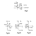
- Figure 3 is a rotating vector diagram of an arbitrary radio signal r(t, ⁇ ) which is to be transmitted with an absolute magnitude (amplitude) R(t, ⁇ ) and a phase angle ⁇ (t, ⁇ ).
- the radio signal is divided into two quadrature components I(t, ⁇ ) and Q(t, ⁇ ), which constitute "the projections" of the two carrierwave components cos w c t and sine w c t respectively of the carrierwave components and phase displaced through 90°.
- the quadrature components I(t, ⁇ ) and Q(t, ⁇ ) are stored in the table units ST and CT respectively in the modulator shown in Figure 2, for all possible signal vectors ⁇ .
- r(t, ⁇ ) R(t, ⁇ ⁇ ) ⁇ cos [w c t + ⁇ (t, ⁇ ⁇ )]
- ⁇ (t, ⁇ ⁇ ) arg [I(t, ⁇ ⁇ ) + j Q(t, ⁇ ⁇ )]
- Figures 4a-4c illustrate three different radiosignals (r(t, ⁇ ) corresponding to three different signal vectors ⁇ 1, ⁇ 2 and ⁇ 3, which are delivered from the shift register D1-D8 and the counter QM.
- Each of the signal vectors indicates the two quadrature components I(t, ⁇ ) in the table units ST and CT. These components are stored respectively as a sine and cosine waveform in the table units.
- the waveform samples are brought forward in sequence with the aid of the counter SR, and the thus obtained digital values are applied to the digital-analogue converters DAC1, DAC2.
- the signals are then low-pass filtered in the filters FR1, FR2 prior to modulation of the carrier waveform components in the multipliers M1, M2 and addition in the summing circuit ADD.
- the aforedescribed modulation method is linear, i.e. the relationship between incoming signal vectors ⁇ and the output signals I(t, ⁇ ) and Q(t, ⁇ ) present a number of linear properties.
- the problem of obtaining a linear end amplifier F ( Figure 2) can occur in particular.
- the method proposed in accordance with the invention ignores the problem of linearizing the end amplifier and instead endeavours to compensate for this non-linearity in the table units ST and CT.
- H R and H ⁇ for the input signal amplitude R1 and its phase angle ⁇ 1
- the inverse transfer functions H R ⁇ 1 and H ⁇ ⁇ 1 can be calculated by measuring a number of output signals R2 for a given number of input signals R1 and constitute static time-independent functions.
- H R and H ⁇ are statically time-independent functions, these functions can be stored in the tables ST and CT for the transfer function of a given final amplifier.
- the value of R of a given signal vector ⁇ can be calculated from the relationship: since I(t, ⁇ ) and Q(t, ⁇ ) for the signal vector is stored in respective table units ST, CT.
- H R and H ⁇ and therewith also H R ⁇ 1 and H ⁇ ⁇ 1 can be calculated. This enables the new coefficients in (t, ⁇ ) and q(t, ⁇ ) for the signal vector ⁇ to be calculated from the relationship (1) above.
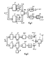
- Figure 5 is a simplified block diagram which illustrates those memory and arithmetical units which effect modification of the quadrature components I(t, ⁇ ), Q(t, ⁇ ) stored in the table units ST and CT.
- the memory unit MH1 stores a quantity of inverted values of the amplifying factor H R (R), i.e. H R ⁇ 1(R) for different input signals R to the end amplifier F.
- the values H R (R) can be obtained by carrying out measurements on the amplifier F and, according to the aforegoing, constitute a static, time-independent function of R.
- the memory unit MH2 stores corresponding values H ⁇ (R) of the phase characteristic of the end amplifier F, which similar to H R (R) is static and time-independent.
- the memories MH1, MH2 thus constitute static addresssable ROM:s.
- H ⁇ (R) in the memory unit MH2 is applied to a table unit MS which calculates sine H ⁇ (R) and cos H ⁇ (R). These two values are transferred to the table units ST and CT and are multiplied by the non-modified values I(t1, ⁇ ), Q(t1, ⁇ ) according to relationship (1) above.
- the value of H R ⁇ 1 (R) is delivered to the memory unit MH1 at the same time and is multiplied by I(t1, ⁇ ), Q(t1, ⁇ ) according to (1).
- the values i(t1, ⁇ ), q(t1, ⁇ ) are, at the same time, delivered to the digital-analogue converters DAC1, DAC2 over the busses b2.
- the above method for compensating non-linearities can also be applied with a quadrature modulator of the configuration illustrated in Figure 6.
- the waveform generator tables have been divided into several part tables: One I-table and one Q-table of simplified form and two mutually identical waveform tables SV and CV.
- the coefficients in the tables ST and CT are modified in accordance with the method above described.
Landscapes
- Engineering & Computer Science (AREA)
- Physics & Mathematics (AREA)
- Power Engineering (AREA)
- Computer Networks & Wireless Communication (AREA)
- Signal Processing (AREA)
- Nonlinear Science (AREA)
- Spectroscopy & Molecular Physics (AREA)
- Digital Transmission Methods That Use Modulated Carrier Waves (AREA)
- Amplifiers (AREA)
Applications Claiming Priority (2)
| Application Number | Priority Date | Filing Date | Title |
|---|---|---|---|
| SE9000219A SE465494B (sv) | 1990-01-22 | 1990-01-22 | Foerfarande att kompensera foer olineariteter i en slutfoerstaerkare |
| SE9000219 | 1990-01-22 |
Publications (2)
| Publication Number | Publication Date |
|---|---|
| EP0441110A1 true EP0441110A1 (de) | 1991-08-14 |
| EP0441110B1 EP0441110B1 (de) | 1995-11-02 |
Family
ID=20378316
Family Applications (1)
| Application Number | Title | Priority Date | Filing Date |
|---|---|---|---|
| EP90850404A Expired - Lifetime EP0441110B1 (de) | 1990-01-22 | 1990-12-13 | Verfahren zum Ausgleich der Nichtlinearitäten in einem Endverstärker eines Radiosenders |
Country Status (14)
| Country | Link |
|---|---|
| US (1) | US5191597A (de) |
| EP (1) | EP0441110B1 (de) |
| JP (1) | JP3034033B2 (de) |
| KR (1) | KR0133552B1 (de) |
| CN (1) | CN1024383C (de) |
| AU (1) | AU633189B2 (de) |
| BR (1) | BR9007227A (de) |
| CA (1) | CA2050350C (de) |
| DE (1) | DE69023326T2 (de) |
| HK (1) | HK36896A (de) |
| MY (1) | MY104811A (de) |
| NZ (1) | NZ236504A (de) |
| SE (1) | SE465494B (de) |
| WO (1) | WO1991011053A1 (de) |
Cited By (7)
| Publication number | Priority date | Publication date | Assignee | Title |
|---|---|---|---|---|
| EP0608697A1 (de) * | 1993-01-29 | 1994-08-03 | TELEFUNKEN Sendertechnik GmbH | Modulationsverfahren und -schaltung für HF-Signale |
| WO1996008866A1 (en) * | 1994-09-14 | 1996-03-21 | Ericsson Inc. | Efficient linear power amplification |
| EP0797323A1 (de) * | 1996-03-22 | 1997-09-24 | Thomson-Csf | Funksender für digitale Rundfunksignale |
| WO1997044940A1 (en) * | 1996-05-24 | 1997-11-27 | International Business Machines Corporation | An apparatus, method and article of manufacture for carrier frequency compensation in an fm radio transmitter |
| WO1999066637A1 (en) * | 1998-06-19 | 1999-12-23 | Datum Telegraphic Inc. | Circuit and methods for compensating for imperfections in amplification chains in a linc or other amplification system |
| CN1088287C (zh) * | 1997-01-31 | 2002-07-24 | 三星电子株式会社 | 线性功率放大器和用于消除互调失真信号的方法 |
| EP1143677A3 (de) * | 2000-04-03 | 2004-08-25 | Victor Company of Japan, Ltd. | Quadraturmodulation |
Families Citing this family (34)
| Publication number | Priority date | Publication date | Assignee | Title |
|---|---|---|---|---|
| CA2094710C (en) * | 1990-10-23 | 1998-12-01 | Robert Clyde Dixon | Method and apparatus for establishing spread spectrum communications |
| GB9111926D0 (en) * | 1991-06-04 | 1991-07-24 | Nat Transcommunications Ltd | An improved method of video noise reduction using non-linear pre/de-emphasis |
| US6088590A (en) | 1993-11-01 | 2000-07-11 | Omnipoint Corporation | Method and system for mobile controlled handoff and link maintenance in spread spectrum communication |
| US6005856A (en) | 1993-11-01 | 1999-12-21 | Omnipoint Corporation | Communication protocol for spread spectrum wireless communication system |
| US5832028A (en) | 1994-09-09 | 1998-11-03 | Omnipoint Corporation | Method and apparatus for coherent serial correlation of a spread spectrum signal |
| US5963586A (en) | 1994-09-09 | 1999-10-05 | Omnipoint Corporation | Method and apparatus for parallel noncoherent correlation of a spread spectrum signal |
| US5953370A (en) | 1994-09-09 | 1999-09-14 | Omnipoint Corporation | Apparatus for receiving and correlating a spread spectrum signal |
| US5754585A (en) | 1994-09-09 | 1998-05-19 | Omnipoint Corporation | Method and apparatus for serial noncoherent correlation of a spread spectrum signal |
| US5754584A (en) | 1994-09-09 | 1998-05-19 | Omnipoint Corporation | Non-coherent spread-spectrum continuous-phase modulation communication system |
| US5648982A (en) | 1994-09-09 | 1997-07-15 | Omnipoint Corporation | Spread spectrum transmitter |
| US5757847A (en) | 1994-09-09 | 1998-05-26 | Omnipoint Corporation | Method and apparatus for decoding a phase encoded signal |
| US5610940A (en) | 1994-09-09 | 1997-03-11 | Omnipoint Corporation | Method and apparatus for noncoherent reception and correlation of a continous phase modulated signal |
| US5881100A (en) | 1994-09-09 | 1999-03-09 | Omnipoint Corporation | Method and apparatus for coherent correlation of a spread spectrum signal |
| US5856998A (en) | 1994-09-09 | 1999-01-05 | Omnipoint Corporation | Method and apparatus for correlating a continuous phase modulated spread spectrum signal |
| US5680414A (en) | 1994-09-09 | 1997-10-21 | Omnipoint Corporation | Synchronization apparatus and method for spread spectrum receiver |
| US5692007A (en) | 1994-09-09 | 1997-11-25 | Omnipoint Corporation | Method and apparatus for differential phase encoding and decoding in spread-spectrum communication systems with continuous-phase modulation |
| US5629956A (en) | 1994-09-09 | 1997-05-13 | Omnipoint Corporation | Method and apparatus for reception and noncoherent serial correlation of a continuous phase modulated signal |
| US5627856A (en) | 1994-09-09 | 1997-05-06 | Omnipoint Corporation | Method and apparatus for receiving and despreading a continuous phase-modulated spread spectrum signal using self-synchronizing correlators |
| US5659574A (en) | 1994-09-09 | 1997-08-19 | Omnipoint Corporation | Multi-bit correlation of continuous phase modulated signals |
| US5548253A (en) * | 1995-04-17 | 1996-08-20 | Omnipoint Corporation | Spectrally efficient quadrature amplitude modulator |
| US5832022A (en) * | 1995-06-02 | 1998-11-03 | Omnipoint Corporation | Method and apparatus for controlling the modulation index of continuous phase modulated (CPM) signals |
| EP0760567A3 (de) * | 1995-08-30 | 2000-09-06 | Siemens Aktiengesellschaft | Digitaler QAM-modulator |
| US5903823A (en) * | 1995-09-19 | 1999-05-11 | Fujitsu Limited | Radio apparatus with distortion compensating function |
| US5617058A (en) * | 1995-11-13 | 1997-04-01 | Apogee Technology, Inc. | Digital signal processing for linearization of small input signals to a tri-state power switch |
| US6185259B1 (en) | 1996-06-12 | 2001-02-06 | Ericsson Inc. | Transmitter/receiver for GMSK and offset-QAM |
| US5815531A (en) * | 1996-06-12 | 1998-09-29 | Ericsson Inc. | Transmitter for encoded data bits |
| US6282228B1 (en) * | 1997-03-20 | 2001-08-28 | Xircom, Inc. | Spread spectrum codes for use in communication |
| FI105366B (fi) * | 1997-10-29 | 2000-07-31 | Nokia Networks Oy | Linearisointimenetelmä ja vahvistinjärjestely |
| US6215354B1 (en) * | 1998-03-06 | 2001-04-10 | Fujant, Inc. | Closed loop calibration for an amplitude reconstruction amplifier |
| US6054896A (en) | 1998-12-17 | 2000-04-25 | Datum Telegraphic Inc. | Controller and associated methods for a linc linear power amplifier |
| US6947469B2 (en) | 1999-05-07 | 2005-09-20 | Intel Corporation | Method and Apparatus for wireless spread spectrum communication with preamble processing period |
| US6794939B2 (en) * | 2002-05-31 | 2004-09-21 | Lucent Technologies Inc. | Signal predistortion using a combination of multiple predistortion techniques |
| FR2860109A1 (fr) * | 2003-09-22 | 2005-03-25 | Thomson Licensing Sa | Recepteur incluant une compensation de linearite dans la bande de reception |
| WO2007110805A2 (en) * | 2006-03-28 | 2007-10-04 | Nxp B.V. | Transmitter with delay mismatch compensation |
Citations (4)
| Publication number | Priority date | Publication date | Assignee | Title |
|---|---|---|---|---|
| DE2304352A1 (de) * | 1972-01-31 | 1973-09-06 | Western Electric Co | Schaltungsanordnung zum verstaerken eines eingangssignals |
| US4229821A (en) * | 1977-09-09 | 1980-10-21 | U.S. Philips Corporation | System for data transmission by means of an angle-modulated carrier of constant amplitude |
| FR2469826A1 (fr) * | 1979-11-14 | 1981-05-22 | Lecoy Pierre | Boucle de detection d'erreur notamment pour circuit de correction de linearite |
| GB2073516A (en) * | 1980-04-01 | 1981-10-14 | Philips Nv | Arrangement for amplifying a modulated carrier signal |
Family Cites Families (10)
| Publication number | Priority date | Publication date | Assignee | Title |
|---|---|---|---|---|
| US4291277A (en) * | 1979-05-16 | 1981-09-22 | Harris Corporation | Adaptive predistortion technique for linearizing a power amplifier for digital data systems |
| JPS5648734A (en) * | 1979-09-28 | 1981-05-02 | Nec Corp | Predistorter |
| US4412337A (en) | 1981-11-04 | 1983-10-25 | Motorola Inc. | Power amplifier and envelope correction circuitry |
| JPS5985166A (ja) * | 1982-10-29 | 1984-05-17 | Fujitsu Ltd | 位相変調器 |
| US4696017A (en) | 1986-02-03 | 1987-09-22 | E-Systems, Inc. | Quadrature signal generator having digitally-controlled phase and amplitude correction |
| JP2540805B2 (ja) * | 1986-04-12 | 1996-10-09 | ソニー株式会社 | ディジタル信号の伝送装置 |
| CH670178A5 (de) * | 1986-06-24 | 1989-05-12 | Bbc Brown Boveri & Cie | |
| DE58907579D1 (de) * | 1989-01-18 | 1994-06-01 | Siemens Ag | Digitaler Verzerrer. |
| FR2652969A1 (fr) * | 1989-10-06 | 1991-04-12 | Philips Electronique Lab | Dispositif de predistorsion pour systeme de transmission numerique. |
| FR2653282B1 (fr) * | 1989-10-18 | 1994-07-22 | Alcatel Transmission | Procede de correction numerique de non linearite d'une chaine d'emission, et dispositif de mise en óoeuvre de ce procede. |
-
1990
- 1990-01-22 SE SE9000219A patent/SE465494B/sv not_active IP Right Cessation
- 1990-12-13 BR BR909007227A patent/BR9007227A/pt not_active IP Right Cessation
- 1990-12-13 DE DE69023326T patent/DE69023326T2/de not_active Expired - Fee Related
- 1990-12-13 WO PCT/SE1990/000829 patent/WO1991011053A1/en not_active Ceased
- 1990-12-13 JP JP3503495A patent/JP3034033B2/ja not_active Expired - Lifetime
- 1990-12-13 CA CA002050350A patent/CA2050350C/en not_active Expired - Fee Related
- 1990-12-13 AU AU72251/91A patent/AU633189B2/en not_active Ceased
- 1990-12-13 EP EP90850404A patent/EP0441110B1/de not_active Expired - Lifetime
- 1990-12-13 KR KR1019910701075A patent/KR0133552B1/ko not_active Expired - Fee Related
- 1990-12-17 NZ NZ236504A patent/NZ236504A/xx unknown
-
1991
- 1991-01-08 MY MYPI91000017A patent/MY104811A/en unknown
- 1991-01-22 US US07/644,442 patent/US5191597A/en not_active Expired - Lifetime
- 1991-01-22 CN CN91100384A patent/CN1024383C/zh not_active Expired - Fee Related
-
1996
- 1996-02-29 HK HK36896A patent/HK36896A/en not_active IP Right Cessation
Patent Citations (4)
| Publication number | Priority date | Publication date | Assignee | Title |
|---|---|---|---|---|
| DE2304352A1 (de) * | 1972-01-31 | 1973-09-06 | Western Electric Co | Schaltungsanordnung zum verstaerken eines eingangssignals |
| US4229821A (en) * | 1977-09-09 | 1980-10-21 | U.S. Philips Corporation | System for data transmission by means of an angle-modulated carrier of constant amplitude |
| FR2469826A1 (fr) * | 1979-11-14 | 1981-05-22 | Lecoy Pierre | Boucle de detection d'erreur notamment pour circuit de correction de linearite |
| GB2073516A (en) * | 1980-04-01 | 1981-10-14 | Philips Nv | Arrangement for amplifying a modulated carrier signal |
Cited By (12)
| Publication number | Priority date | Publication date | Assignee | Title |
|---|---|---|---|---|
| EP0608697A1 (de) * | 1993-01-29 | 1994-08-03 | TELEFUNKEN Sendertechnik GmbH | Modulationsverfahren und -schaltung für HF-Signale |
| WO1996008866A1 (en) * | 1994-09-14 | 1996-03-21 | Ericsson Inc. | Efficient linear power amplification |
| US5694433A (en) * | 1994-09-14 | 1997-12-02 | Ericsson Inc. | Efficient linear power amplification |
| CN1076903C (zh) * | 1994-09-14 | 2001-12-26 | 艾利森公司 | 高效率线性功率放大 |
| EP0797323A1 (de) * | 1996-03-22 | 1997-09-24 | Thomson-Csf | Funksender für digitale Rundfunksignale |
| FR2746562A1 (fr) * | 1996-03-22 | 1997-09-26 | Thomson Csf | Emetteur de signaux de radiophonie digitale |
| WO1997044940A1 (en) * | 1996-05-24 | 1997-11-27 | International Business Machines Corporation | An apparatus, method and article of manufacture for carrier frequency compensation in an fm radio transmitter |
| US5751114A (en) * | 1996-05-24 | 1998-05-12 | International Business Machines Corporation | Apparatus, method and article of manufacture for carrier frequency compensation in a FM radio transmitter |
| CN1088287C (zh) * | 1997-01-31 | 2002-07-24 | 三星电子株式会社 | 线性功率放大器和用于消除互调失真信号的方法 |
| WO1999066637A1 (en) * | 1998-06-19 | 1999-12-23 | Datum Telegraphic Inc. | Circuit and methods for compensating for imperfections in amplification chains in a linc or other amplification system |
| EP1143677A3 (de) * | 2000-04-03 | 2004-08-25 | Victor Company of Japan, Ltd. | Quadraturmodulation |
| US6862321B2 (en) | 2000-04-03 | 2005-03-01 | Victor Company Of Japan, Ltd. | Method and apparatus for generating transmission signal by processing which includes digital quadrature modulation |
Also Published As
| Publication number | Publication date |
|---|---|
| CA2050350C (en) | 2000-07-25 |
| SE9000219L (sv) | 1991-07-23 |
| HK36896A (en) | 1996-03-08 |
| DE69023326D1 (de) | 1995-12-07 |
| AU633189B2 (en) | 1993-01-21 |
| NZ236504A (en) | 1993-05-26 |
| US5191597A (en) | 1993-03-02 |
| CN1024383C (zh) | 1994-04-27 |
| KR920702079A (ko) | 1992-08-12 |
| CA2050350A1 (en) | 1991-07-23 |
| JPH04504494A (ja) | 1992-08-06 |
| AU7225191A (en) | 1991-08-05 |
| JP3034033B2 (ja) | 2000-04-17 |
| EP0441110B1 (de) | 1995-11-02 |
| KR0133552B1 (ko) | 1998-04-23 |
| SE9000219D0 (sv) | 1990-01-22 |
| CN1053719A (zh) | 1991-08-07 |
| SE465494B (sv) | 1991-09-16 |
| DE69023326T2 (de) | 1996-04-11 |
| MY104811A (en) | 1994-05-31 |
| BR9007227A (pt) | 1992-02-18 |
| WO1991011053A1 (en) | 1991-07-25 |
Similar Documents
| Publication | Publication Date | Title |
|---|---|---|
| EP0441110B1 (de) | Verfahren zum Ausgleich der Nichtlinearitäten in einem Endverstärker eines Radiosenders | |
| JP3169803B2 (ja) | 電力増幅器の非線形補償回路 | |
| US6798844B2 (en) | Correction of phase and amplitude imbalance of I/Q modulator | |
| US4584541A (en) | Digital modulator with variations of phase and amplitude modulation | |
| US4700151A (en) | Modulation system capable of improving a transmission system | |
| KR100398302B1 (ko) | 효율적인선형전력증폭 | |
| EP0716526B1 (de) | Verfahren zur Erzeugung von modulierenden Wellenformen konstanter Umhüllung | |
| JP3410355B2 (ja) | 変調器及び変調方法 | |
| JPH07183729A (ja) | 電力増幅器 | |
| US7158582B2 (en) | Digital I/Q modulator having a predistortion | |
| WO2005020430A2 (en) | Pseudo-polar modulation for radio transmitters | |
| EP0170324B1 (de) | Auf Datensignale ansprechende Vorrichtung zur Erregung eines winkelmodulierten Trägersignals konstanter Amplitude | |
| US6996191B1 (en) | Efficient accurate controller for envelope feedforward power amplifiers | |
| JP2728114B2 (ja) | Fm変調回路 | |
| JPH0580856B2 (de) | ||
| US4028641A (en) | Linear phase modulator including a pair of Armstrong modulators | |
| US5942955A (en) | Quasi-GMSK modulator | |
| JPH1075122A (ja) | Fm信号復調方法及びその装置 | |
| US5751198A (en) | Angular modulator with a phase variation divided and integrated | |
| JP2001527330A (ja) | スペクトルが狭く、エンベロープがほぼ一定のデジタル信号の変調 | |
| US5905413A (en) | Angular modulator with a phase variation divided and integrated | |
| JP3134251B2 (ja) | 直交変調信号発生回路 | |
| Ghaderi | Adaptive linearization of efficient high power amplifiers using polynomial predistortion with global optimization | |
| JP2001036353A (ja) | 歪み補償方法および無線通信装置 | |
| JP2514113B2 (ja) | スペクトル拡散復調装置 |
Legal Events
| Date | Code | Title | Description |
|---|---|---|---|
| PUAI | Public reference made under article 153(3) epc to a published international application that has entered the european phase |
Free format text: ORIGINAL CODE: 0009012 |
|
| AK | Designated contracting states |
Kind code of ref document: A1 Designated state(s): DE FR GB |
|
| 17P | Request for examination filed |
Effective date: 19911223 |
|
| 17Q | First examination report despatched |
Effective date: 19940328 |
|
| GRAA | (expected) grant |
Free format text: ORIGINAL CODE: 0009210 |
|
| AK | Designated contracting states |
Kind code of ref document: B1 Designated state(s): DE FR GB |
|
| REF | Corresponds to: |
Ref document number: 69023326 Country of ref document: DE Date of ref document: 19951207 |
|
| ET | Fr: translation filed | ||
| PLBE | No opposition filed within time limit |
Free format text: ORIGINAL CODE: 0009261 |
|
| STAA | Information on the status of an ep patent application or granted ep patent |
Free format text: STATUS: NO OPPOSITION FILED WITHIN TIME LIMIT |
|
| 26N | No opposition filed | ||
| PGFP | Annual fee paid to national office [announced via postgrant information from national office to epo] |
Ref country code: FR Payment date: 20011120 Year of fee payment: 12 |
|
| PGFP | Annual fee paid to national office [announced via postgrant information from national office to epo] |
Ref country code: GB Payment date: 20011122 Year of fee payment: 12 |
|
| PGFP | Annual fee paid to national office [announced via postgrant information from national office to epo] |
Ref country code: DE Payment date: 20011123 Year of fee payment: 12 |
|
| REG | Reference to a national code |
Ref country code: GB Ref legal event code: IF02 |
|
| PG25 | Lapsed in a contracting state [announced via postgrant information from national office to epo] |
Ref country code: GB Free format text: LAPSE BECAUSE OF NON-PAYMENT OF DUE FEES Effective date: 20021213 |
|
| PG25 | Lapsed in a contracting state [announced via postgrant information from national office to epo] |
Ref country code: DE Free format text: LAPSE BECAUSE OF NON-PAYMENT OF DUE FEES Effective date: 20030701 |
|
| GBPC | Gb: european patent ceased through non-payment of renewal fee |
Effective date: 20021213 |
|
| PG25 | Lapsed in a contracting state [announced via postgrant information from national office to epo] |
Ref country code: FR Free format text: LAPSE BECAUSE OF NON-PAYMENT OF DUE FEES Effective date: 20030901 |
|
| REG | Reference to a national code |
Ref country code: FR Ref legal event code: ST |