EP0441130A2 - Dispositif de contrôle des variations rapides de pression d'air dans les moyens de transport de personnes - Google Patents
Dispositif de contrôle des variations rapides de pression d'air dans les moyens de transport de personnes Download PDFInfo
- Publication number
- EP0441130A2 EP0441130A2 EP19910100323 EP91100323A EP0441130A2 EP 0441130 A2 EP0441130 A2 EP 0441130A2 EP 19910100323 EP19910100323 EP 19910100323 EP 91100323 A EP91100323 A EP 91100323A EP 0441130 A2 EP0441130 A2 EP 0441130A2
- Authority
- EP
- European Patent Office
- Prior art keywords
- pressure
- air pressure
- measurement
- microprocessor
- order
- Prior art date
- Legal status (The legal status is an assumption and is not a legal conclusion. Google has not performed a legal analysis and makes no representation as to the accuracy of the status listed.)
- Withdrawn
Links
- 238000011156 evaluation Methods 0.000 claims description 11
- 238000005259 measurement Methods 0.000 claims description 9
- 230000006870 function Effects 0.000 claims description 4
- 230000003936 working memory Effects 0.000 claims description 4
- 230000015654 memory Effects 0.000 claims description 3
- 230000006978 adaptation Effects 0.000 claims 1
- 230000002123 temporal effect Effects 0.000 claims 1
- 238000011144 upstream manufacturing Methods 0.000 claims 1
- 230000007423 decrease Effects 0.000 abstract description 2
- 230000000694 effects Effects 0.000 abstract description 2
- 206010052137 Ear discomfort Diseases 0.000 abstract 1
- 230000004807 localization Effects 0.000 abstract 1
- 238000010586 diagram Methods 0.000 description 2
- 238000007789 sealing Methods 0.000 description 2
- 206010014020 Ear pain Diseases 0.000 description 1
- 238000001514 detection method Methods 0.000 description 1
- 208000007176 earache Diseases 0.000 description 1
- 239000012528 membrane Substances 0.000 description 1
- 230000033764 rhythmic process Effects 0.000 description 1
- 238000005070 sampling Methods 0.000 description 1
- 230000001052 transient effect Effects 0.000 description 1
Images

Classifications
-
- G—PHYSICS
- G01—MEASURING; TESTING
- G01L—MEASURING FORCE, STRESS, TORQUE, WORK, MECHANICAL POWER, MECHANICAL EFFICIENCY, OR FLUID PRESSURE
- G01L19/00—Details of, or accessories for, apparatus for measuring steady or quasi-steady pressure of a fluent medium insofar as such details or accessories are not special to particular types of pressure gauges
- G01L19/08—Means for indicating or recording, e.g. for remote indication
- G01L19/083—Means for indicating or recording, e.g. for remote indication electrical
Definitions
- the invention relates to a device for measuring short-term air pressure fluctuations according to the preamble of claim 1.
- PA 39 40 719.5 A device that relates to this problem is described in PA 39 40 719.5.
- the solution is there by pneumatic means with a pressure compensating tank and throttle valve.
- a high-sensitivity differential pressure sensor is required.
- DE 28 56 710 Another invention relating to the measurement of pressures is shown in DE 28 56 710; here a device for measuring cyclically pulsating, according to duration and size of negative pressures in piping systems is described. It is not possible to use this device for measuring non-pulsating, randomly distributed overpressures in large-scale systems while taking into account longer-term atmospheric and altitude-related fluctuations in air pressure and the possibility of locating leaks.
- the invention is therefore based on the object of detecting and evaluating physiologically unpleasant air pressure surges with absolute pressure transducers and purely electronic processing of measured values and, if possible, localizing the causes of the leaks with sufficient accuracy. Atmospheric pressure changes and pressure changes as a result of different line heights above sea level must be recorded and continuously taken into account. Furthermore, it is required that the physiological evaluation numbers are variable, i.e. should be freely entered, because air pressure surges in a open-plan car work differently than in a closed compartment.
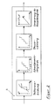
- An absolute pressure sensor 1 continuously records the interior pressure of the passenger compartment, a downstream analog-to-digital converter (ADC) 2 digitizes the measured values; the evaluation takes place in the downstream freely programmable microprocessor 3.
- ADC analog-to-digital converter
- the pressure gradient - if present - is calculated at times t n and t n + 1 , and any sign reversal to the previous step is determined.
- the program part of the microprocessor 3 which carries out the threshold value comparison, several stages (expediently approx. 5 to 10) can be entered for the pressure rise values, for example 50 Pa / s, 100 Pa / s ... 300 Pa / s.
- the time duration of the pressure increase ie the time period in which the pressure increase reaches or exceeds the predetermined threshold values, is determined in the second step.
- a count signal is generated, which is added up for the relevant threshold value class and specified on a counter.
- the output signals are generated, which are then output in the required form via a display and evaluation device 4, for example via a display device or via a counter or via a measuring strip plotter.
- the processed output signals are stored in a data memory 5, from where they can be transferred to external evaluation or display devices via an interface 8 if required. This is particularly advantageous when more precise evaluations require more specific and therefore expensive evaluation devices: With a few mobile evaluation devices, many working memories 5 can be evaluated in succession via the interfaces 8. It may be useful, not all
- This interface 8 can be used to write new parameters into the working memory 5 and thus to make them available to the microprocessor 3. This is indicated by the arrows going in both directions between the components 3 and 5 or 5 and 8 in FIG. 1.
- the working memory 5 can be secured against loss of information if the on-board power supply fails, e.g. through battery backup.
- the location of a leak requires the use of several sensibly positioned pressure transducers 1, each with a downstream AD converter 2, and appropriate programming of the microprocessor 3: for example, a measuring strip plotter can be used for output, which plots the pressure profiles of all pressure transducers 1 synchronously over the time axis.
- a measuring strip plotter can be used for output, which plots the pressure profiles of all pressure transducers 1 synchronously over the time axis.
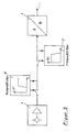
- a variant of FIG. 1 is to connect a high-pass filter 6 to the pressure sensor 1, so that the useful signal manages with a smaller resolution range of the subsequent A-D converter 2 (FIG. 3). It may also be useful to suppress interference frequencies by switching a low-pass filter 7 (anti-aliasing filter) adapted to the sampling rate between the pressure sensor 1 and the A / D converter 2 (FIG. 3). Attention is drawn to the possibility of implementing further filter functions without changing the circuit by programming the microprocessor 3. It is also pointed out the possibility of using a pressure increase sensor instead of an (absolute) pressure sensor 1; even microphones or loudspeakers of certain size classes with pressure-tight membranes are suitable for this function.
- the device according to the invention is characterized by the use of inexpensive building blocks available on the market.
- the purely electronic processing of the measurement signals and the possible off-line evaluation of the data allow the device according to the invention to be accommodated in a handy temperature and shock-proof housing which is also suitable for mobile use. Because of the exclusively electronic data processing, there is a high level of reliability, even in continuous operation.
Landscapes
- Physics & Mathematics (AREA)
- General Physics & Mathematics (AREA)
- Measuring Fluid Pressure (AREA)
Applications Claiming Priority (2)
| Application Number | Priority Date | Filing Date | Title |
|---|---|---|---|
| DE4002271 | 1990-01-26 | ||
| DE19904002271 DE4002271C2 (de) | 1990-01-26 | 1990-01-26 | Verfahren und Vorrichtung zur Drucküberwachung in Reisezugwagen |
Publications (1)
| Publication Number | Publication Date |
|---|---|
| EP0441130A2 true EP0441130A2 (fr) | 1991-08-14 |
Family
ID=6398829
Family Applications (1)
| Application Number | Title | Priority Date | Filing Date |
|---|---|---|---|
| EP19910100323 Withdrawn EP0441130A2 (fr) | 1990-01-26 | 1991-01-11 | Dispositif de contrôle des variations rapides de pression d'air dans les moyens de transport de personnes |
Country Status (3)
| Country | Link |
|---|---|
| EP (1) | EP0441130A2 (fr) |
| DE (1) | DE4002271C2 (fr) |
| HU (1) | HUT58909A (fr) |
Cited By (1)
| Publication number | Priority date | Publication date | Assignee | Title |
|---|---|---|---|---|
| CH708501A1 (de) * | 2013-08-30 | 2015-03-13 | Stadler Bussnang Ag | Verfahren zur Prüfung der Druckdichtigkeit eines Schienenfahrzeugs und Messerinrichtung zur Durchführung des Verfahrens. |
Families Citing this family (1)
| Publication number | Priority date | Publication date | Assignee | Title |
|---|---|---|---|---|
| DE10239996A1 (de) * | 2002-08-27 | 2004-03-18 | Db Reise & Touristik Ag | Verfahren zur Dichtheitsprüfung von Fahrzeugen |
Family Cites Families (2)
| Publication number | Priority date | Publication date | Assignee | Title |
|---|---|---|---|---|
| DE2719627A1 (de) * | 1977-05-03 | 1978-11-09 | Daimler Benz Ag | Verfahren und vorrichtung zur bestimmung des statischen innendrucks vorzugsweise in einem kraftfahrzeug |
| NL7714603A (nl) * | 1977-12-30 | 1979-07-03 | Veco Beheer Electro Photo | Electronische pulsatortester. |
-
1990
- 1990-01-26 DE DE19904002271 patent/DE4002271C2/de not_active Expired - Fee Related
-
1991
- 1991-01-11 EP EP19910100323 patent/EP0441130A2/fr not_active Withdrawn
- 1991-01-15 HU HU10291A patent/HUT58909A/hu unknown
Cited By (1)
| Publication number | Priority date | Publication date | Assignee | Title |
|---|---|---|---|---|
| CH708501A1 (de) * | 2013-08-30 | 2015-03-13 | Stadler Bussnang Ag | Verfahren zur Prüfung der Druckdichtigkeit eines Schienenfahrzeugs und Messerinrichtung zur Durchführung des Verfahrens. |
Also Published As
| Publication number | Publication date |
|---|---|
| DE4002271A1 (de) | 1991-09-26 |
| HUT58909A (en) | 1992-03-30 |
| HU910102D0 (en) | 1991-08-28 |
| DE4002271C2 (de) | 1994-05-19 |
Similar Documents
| Publication | Publication Date | Title |
|---|---|---|
| DE19580682B4 (de) | Einrichtung und Verfahren zum Detektieren von Defektzuständen in Schienenfahrzeugrädern und Gleiswegen | |
| DE19580680B4 (de) | Mobile Nachführungseinheit und Verfahren zum Detektieren von Defektzuständen in Schienenfahrzeugrädern und Gleiswegen | |
| DE69214098T2 (de) | Fahrzeugnavigationssystem | |
| DE19852220C2 (de) | Verfahren zur Erkennung von Schäden im Schienenverkehr | |
| DE19836081A1 (de) | Verfahren zur Früherkennung von Schäden an Schienenfahrzeugen | |
| WO2018041569A1 (fr) | Dispositif et procédé pour déterminer l'état de voies ferrées | |
| DE102009037637A1 (de) | Verfahren und elektronische Einrichtung zur Zustandsüberwachung von Bauteilen bei Schienenfahrzeugen | |
| DE102015215572A1 (de) | Prüfeinrichtung und Verfahren zur Überprüfung eines definierten Profils von einem Zugverband aus Fahrzeugen, insbesondere Schienenfahrzeugen | |
| EP0432669A2 (fr) | Procédé et dispositif de surveillance de la pression de l'air dans les voitures ferroviaires | |
| DE4237527A1 (de) | Verfahren und Vorrichtung zur Rahmendichtungsprüfung | |
| EP0661528B1 (fr) | Détection de défauts dans une canalisation pour fluide, écouvillon de son avec un blindage anti- bruits | |
| ONO et al. | Development and operation of a system for diagnosing the condition of regional railways tracks | |
| DE4002271C2 (de) | Verfahren und Vorrichtung zur Drucküberwachung in Reisezugwagen | |
| DE102013105397B4 (de) | Zustandsüberwachung eines Schienenfahrzeugs | |
| DE10147906A1 (de) | Verfahren zur Dichtigkeitsmessung von Wagen, insbesondere Zugwagen, und Vorrichtung zur Durchfüchrung des Messverfahrens | |
| CN112622984B (zh) | 基于不同频次过车的车辆检测报警方法及系统 | |
| DE19901532A1 (de) | Vorrichtung und Verfahren zur Ermittlung und Diagnose erhöhten Kraftstoffverbrauchs eines Fahrzeugs | |
| DE10062606A1 (de) | Verfahren und Einrichtung zum Überwachen des mechanischen Zustands von elektrisch angetriebenen Fahrzeugen im regulären Fahrbetrieb | |
| EP3495847B2 (fr) | Agencement de tachygraphe et procédé de fonctionnement d'un agencement de tachygraphe | |
| DE68912245T2 (de) | Drehungssensor. | |
| DE102020111814A1 (de) | Verfahren zur Dichtigkeitsprüfung eines Prüfkörpers und Prüfvorrichtung sowie Hochvoltspeicher | |
| CH715634A2 (de) | Verfahren zur Leckageortung bei Fahrzeugen sowie dafür ausgestattetes Fahrzeug. | |
| DE2807631A1 (de) | Verfahren zur bestimmung von undichtigkeiten von im erdboden verlegten wasserleitungen | |
| CH708501A1 (de) | Verfahren zur Prüfung der Druckdichtigkeit eines Schienenfahrzeugs und Messerinrichtung zur Durchführung des Verfahrens. | |
| WO2000032458A1 (fr) | Procede et dispositif pour determiner des etats et/ou des changements d'etat dans des installations de trafic ferroviaire |
Legal Events
| Date | Code | Title | Description |
|---|---|---|---|
| PUAI | Public reference made under article 153(3) epc to a published international application that has entered the european phase |
Free format text: ORIGINAL CODE: 0009012 |
|
| AK | Designated contracting states |
Kind code of ref document: A2 Designated state(s): AT CH DE ES FR GB IT LI |
|
| STAA | Information on the status of an ep patent application or granted ep patent |
Free format text: STATUS: THE APPLICATION HAS BEEN WITHDRAWN |
|
| 18W | Application withdrawn |
Withdrawal date: 19920305 |
|
| R18W | Application withdrawn (corrected) |
Effective date: 19920305 |