EP0441151A1 - Robinet avec protection contre le reflux d'eau - Google Patents
Robinet avec protection contre le reflux d'eau Download PDFInfo
- Publication number
- EP0441151A1 EP0441151A1 EP19910100638 EP91100638A EP0441151A1 EP 0441151 A1 EP0441151 A1 EP 0441151A1 EP 19910100638 EP19910100638 EP 19910100638 EP 91100638 A EP91100638 A EP 91100638A EP 0441151 A1 EP0441151 A1 EP 0441151A1
- Authority
- EP
- European Patent Office
- Prior art keywords
- valve
- water
- opening
- water tap
- line
- Prior art date
- Legal status (The legal status is an assumption and is not a legal conclusion. Google has not performed a legal analysis and makes no representation as to the accuracy of the status listed.)
- Granted
Links
- XLYOFNOQVPJJNP-UHFFFAOYSA-N water Substances O XLYOFNOQVPJJNP-UHFFFAOYSA-N 0.000 claims abstract description 80
- 238000009423 ventilation Methods 0.000 claims description 16
- 238000007789 sealing Methods 0.000 claims description 7
- 238000011144 upstream manufacturing Methods 0.000 claims description 6
- 238000007599 discharging Methods 0.000 claims 2
- 238000005273 aeration Methods 0.000 abstract description 5
- 239000007921 spray Substances 0.000 abstract 2
- 238000000034 method Methods 0.000 description 4
- 238000010521 absorption reaction Methods 0.000 description 1
- 230000015572 biosynthetic process Effects 0.000 description 1
- 239000007788 liquid Substances 0.000 description 1
- 239000007787 solid Substances 0.000 description 1
- 239000002351 wastewater Substances 0.000 description 1
Images


Classifications
-
- E—FIXED CONSTRUCTIONS
- E03—WATER SUPPLY; SEWERAGE
- E03C—DOMESTIC PLUMBING INSTALLATIONS FOR FRESH WATER OR WASTE WATER; SINKS
- E03C1/00—Domestic plumbing installations for fresh water or waste water; Sinks
- E03C1/02—Plumbing installations for fresh water
- E03C1/04—Water-basin installations specially adapted to wash-basins or baths
-
- E—FIXED CONSTRUCTIONS
- E03—WATER SUPPLY; SEWERAGE
- E03C—DOMESTIC PLUMBING INSTALLATIONS FOR FRESH WATER OR WASTE WATER; SINKS
- E03C1/00—Domestic plumbing installations for fresh water or waste water; Sinks
- E03C1/02—Plumbing installations for fresh water
- E03C1/10—Devices for preventing contamination of drinking-water pipes, e.g. means for aerating self-closing flushing valves
- E03C1/102—Devices for preventing contamination of drinking-water pipes, e.g. means for aerating self-closing flushing valves using an air gap device
-
- E—FIXED CONSTRUCTIONS
- E03—WATER SUPPLY; SEWERAGE
- E03C—DOMESTIC PLUMBING INSTALLATIONS FOR FRESH WATER OR WASTE WATER; SINKS
- E03C1/00—Domestic plumbing installations for fresh water or waste water; Sinks
- E03C1/02—Plumbing installations for fresh water
- E03C1/10—Devices for preventing contamination of drinking-water pipes, e.g. means for aerating self-closing flushing valves
- E03C1/106—Devices for preventing contamination of drinking-water pipes, e.g. means for aerating self-closing flushing valves using two or more check valves
-
- E—FIXED CONSTRUCTIONS
- E03—WATER SUPPLY; SEWERAGE
- E03C—DOMESTIC PLUMBING INSTALLATIONS FOR FRESH WATER OR WASTE WATER; SINKS
- E03C1/00—Domestic plumbing installations for fresh water or waste water; Sinks
- E03C1/02—Plumbing installations for fresh water
- E03C1/10—Devices for preventing contamination of drinking-water pipes, e.g. means for aerating self-closing flushing valves
- E03C1/108—Devices for preventing contamination of drinking-water pipes, e.g. means for aerating self-closing flushing valves having an aerating valve
-
- Y—GENERAL TAGGING OF NEW TECHNOLOGICAL DEVELOPMENTS; GENERAL TAGGING OF CROSS-SECTIONAL TECHNOLOGIES SPANNING OVER SEVERAL SECTIONS OF THE IPC; TECHNICAL SUBJECTS COVERED BY FORMER USPC CROSS-REFERENCE ART COLLECTIONS [XRACs] AND DIGESTS
- Y10—TECHNICAL SUBJECTS COVERED BY FORMER USPC
- Y10T—TECHNICAL SUBJECTS COVERED BY FORMER US CLASSIFICATION
- Y10T137/00—Fluid handling
- Y10T137/3149—Back flow prevention by vacuum breaking [e.g., anti-siphon devices]
- Y10T137/3185—Air vent in liquid flow line
- Y10T137/3294—Valved
- Y10T137/3331—With co-acting valve in liquid flow path
-
- Y—GENERAL TAGGING OF NEW TECHNOLOGICAL DEVELOPMENTS; GENERAL TAGGING OF CROSS-SECTIONAL TECHNOLOGIES SPANNING OVER SEVERAL SECTIONS OF THE IPC; TECHNICAL SUBJECTS COVERED BY FORMER USPC CROSS-REFERENCE ART COLLECTIONS [XRACs] AND DIGESTS
- Y10—TECHNICAL SUBJECTS COVERED BY FORMER USPC
- Y10T—TECHNICAL SUBJECTS COVERED BY FORMER US CLASSIFICATION
- Y10T137/00—Fluid handling
- Y10T137/5762—With leakage or drip collecting
Definitions
- the invention relates to a water tap, in particular for wash basins and / or sinks, with a housing that can be connected to the supply line network and a water outlet designed as a pull-out hose shower, wherein a ventilation device is provided to prevent the suction of process water back through the hose shower.
- a ventilation device is known from the document DE 36 03 503 A1.
- This ventilation device is integrated above the wash and sink in the housing of the water tap valve, so that the housing is to be made correspondingly large.
- ventilation devices are not mandatory in different countries, so that for example for reasons of price, the outlet fitting is to be offered with and without a ventilation device.
- the invention has for its object to provide a reliable-acting ventilation device which can be installed essentially independently of the water tap, in particular under the washstand or sink.
- At least one interrupter valve is provided in the line for the water outlet, the valve closure member is movably arranged in a valve housing between two opposing valve seats, one valve seat opening to the atmosphere and the other valve seat the inflow opening for the outflowing water encloses, while the outlet opening for the water outlet is provided outside the valve seats in the valve housing, the valve closure member being tightened against the valve seat with the inlet opening with a certain force such that it bears against the outlet pipe at least at atmospheric pressure.
- the ventilation device consisting essentially of an interrupter valve can be installed independently of the highest possible water level in the sink or sink, in particular also below the sink or sink.
- the interrupter valve is designed as a two-way valve, wherein the valve closure member closes the ventilation opening at a line pressure above atmospheric pressure and releases the water passage to the water outlet, while at an atmospheric pressure in the line the valve closure member, for example with the aid of a spring, is taut from the opening to the atmosphere in the direction of the valve seat with the inflow opening and closes the inflow opening.
- this prevents water from flowing back in the direction of the water tap valve and, on the other hand, aerates the rest of the hose line to the hose shower via the opening to the atmosphere. With the device, an unwanted sucking back of process water can therefore be avoided with great certainty.
- Further advantageous embodiments of the invention are specified in claims 2 to 13.
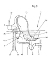
- a sink 10 is formed, a nozzle 2 being attached to the table.
- the nozzle 2 is supplied with cold and hot water from the supply line network via the connecting lines 21, 22.
- an actuating handle 23 which can be set in two degrees of freedom, tempered mixed water can be produced in the dispensing valve 2.
- the mixing ratio or the mixed water temperature can be set, for example, by an actuating movement in the first degree of freedom, while the total water flow rate can be set in the second degree of freedom with the actuating handle 23.
- the mixed water generated in the dispensing valve 2 is fed via the outlet pipe 24, the hose line 25, the hose shower 26 to the water outlet 261 designed as a shower base.
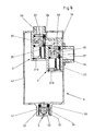
- the interrupter valve 3 is formed twice in succession in a housing 31, the housing 31 being arranged in a box 4 in which a connection 41 for a line 43 to the sewer 11 of the sink 1 is provided in the bottom region is. On the side wall of the box 4, above the connection 41, an opening 42 is provided for ventilation and a possible overflow of leak water.
- the housing 31 is fixed in the box 4 with a socket, in which the connection openings 36 and 37 are formed.
- the connection opening 36 is formed perpendicularly and is used to connect to the outlet pipe 24 of the nozzle 2.
- a two-way valve Downstream of the connection opening 36, a two-way valve is arranged as a structural unit in a bore.
- the two-way valve is one as a ball formed valve closure member 32 is provided which is movable between two valve seats 33, 34 arranged vertically one above the other.
- the valve seat 33 In the valve seat 33, the inflow opening for the mixed water generated in the nozzle 2 is formed, while the valve seat 34 has an opening to the atmosphere.
- outlet openings 38 are formed in the lateral surface between the two valve seats 33, 34.
- An identically identical interrupter valve 3 is arranged downstream of the upstream valve 3, an angular channel being formed in the valve housing 31, which connects the outlet opening 38 of the upstream valve to the inlet opening of the valve seat 33 of the downstream valve.
- a spring 35 is provided, with which the valve closure member 32 is tightened against the valve seat 33.
- the force of the spring 35 is dimensioned such that at least at a pressure in the connection opening 36, which corresponds to the pressure of the external atmosphere, the valve closure member 32 is pressed into its closed position on the valve seat 33.
- the ventilation device has the following mode of operation:
- tempered mixed water is generated in the nozzle 2, which is supplied via the outlet pipe 24 to the connection opening 36 in the valve housing 31 of the two interrupter valves 3.
- the two valve closure members 32 are pressed by the water pressure against the valve seat 34 against the force of the spring 35, so that in each case the opening to the atmosphere in the valve seat 34 is closed, so that water cannot escape into the box 4.
- the mixed water thus flows through the two outlet openings 38 into the connecting piece 37 to which the hose line 25 is connected to the hose shower 26, the mixed water exiting at the water outlet 261 of the shower base into the open or in this position into the sink 10 filled with water.
- a backflow preventer can be expediently provided in the area of the hose shower 26. In many cases, such a backflow preventer is provided as standard in the shower heads.
- the interrupter valve 3 is designed in two, the level of the outlet opening 38 of the upstream valve being located above the valve seat 33 of the downstream valve.
- the twin training was only chosen with a view to a particularly high level of security against the sucking back of contaminated water.
- the ventilation device is also functional with an interruption valve 3.
- the ventilation device integrated in the box 4 is fixed under the sink near the nozzle 4 on the outlet pipe 24.
- the aeration unit can also be installed in other suitable places, it being completely irrelevant at what height the aeration device for the water level in the sink 10 is located.
- a sink 10 is provided, a nozzle 2 being attached to the table.
- the nozzle 2 is supplied with cold and hot water from the supply line network via the connecting lines 21, 22.
- an actuating handle 23 which can be set in two degrees of freedom, tempered mixed water can be produced in the dispensing valve 2.
- the mixing ratio or the mixed water temperature can be set, for example, while in the second degree of freedom with the actuating handle 23 the total water flow rate is adjustable.
- the mixed water generated in the dispensing valve 2 is fed via the outlet pipe 24, the hose line 25, the hose shower 26 to the water outlet 261 designed as a shower base.
- a break valve 3 designed as a twin is arranged between the outlet pipe 24 and the hose line 25, a break valve 3 designed as a twin is arranged.
- two valve closure members 32 are arranged one behind the other in a valve housing 31.
- Each closure member 32 cooperates with a valve seat 33 at the water inlet opening and with a valve seat 34 to the atmosphere.
- the valve closure member 32 designed as a ball is tightened against the valve seat 33 with a spring 35.
- the valve seat 34 is in each case connected directly to the atmosphere via an opening 310.
- a connection opening 36 is formed vertically on the valve housing 31 and a further connection opening 37 is provided horizontally downstream for the connection of the hose line 35. During the ventilation process, dripping water can escape from the valve housing 31 via the openings 310.
- the valve housing 31 is arranged in a box 4, the valve housing 31 being fixed in the box 4 with the connecting pieces 36, 37.
- an opening 42 is provided in the side wall of the box 4 for ventilation and a possible overflow of leakage water.
- a connection 41 is formed in the bottom area of the box 4.
- a float valve 5 is used as a structural unit in an approximately cylindrical stepped bore.
- a sealing seat 53 is formed in a sleeve 54 in the upper region, on which a floatable ball is assigned as a closure member 51 below.
- a holding basket 52 is also provided for guiding and holding the closure member 51.
- the assembly of the float valve 5 combined in the sleeve 54 can thus be inserted from the outside in a sealed manner into the stepped bore of the connection 41 with the aid of a sealing ring 55 provided in the outer jacket of the sleeve 54.
- the connection 41 as can be seen in particular from FIG. 3, is connected by the line 43 to the sewer 11 below the wash basin 10 to the sewer 11.
- the line 43 is connected to the sewer 11 upstream in front of the odor trap 12, so that the drip water from the box 4 can be easily introduced.
- the float valve 5 effectively prevents the backwater which arises when draining rinse water from the odor trap 12, so that waste water can escape via the line 43 into the box 4, since in this case the closure member 51 would float and the outlet in cooperation with the sealing seat 53 prevented.
- the closure member can be designed as a floatable hollow or solid ball or in another suitable shape.
Landscapes
- Health & Medical Sciences (AREA)
- Life Sciences & Earth Sciences (AREA)
- Engineering & Computer Science (AREA)
- Hydrology & Water Resources (AREA)
- Public Health (AREA)
- Water Supply & Treatment (AREA)
- Domestic Plumbing Installations (AREA)
- Bathtubs, Showers, And Their Attachments (AREA)
- Treatment Of Water By Ion Exchange (AREA)
- Check Valves (AREA)
- Joints Allowing Movement (AREA)
- Percussion Or Vibration Massage (AREA)
- Sink And Installation For Waste Water (AREA)
- Confectionery (AREA)
- Self-Closing Valves And Venting Or Aerating Valves (AREA)
- Orthopedics, Nursing, And Contraception (AREA)
- Nozzles (AREA)
Applications Claiming Priority (4)
| Application Number | Priority Date | Filing Date | Title |
|---|---|---|---|
| DE4003353 | 1990-02-05 | ||
| DE19904003353 DE4003353A1 (de) | 1990-02-05 | 1990-02-05 | Wasserzapfarmatur mit ruecksaugsicherung |
| DE4014968 | 1990-05-10 | ||
| DE19904014968 DE4014968A1 (de) | 1990-05-10 | 1990-05-10 | Wasserzapfarmatur mit ruecksaugsicherung |
Publications (2)
| Publication Number | Publication Date |
|---|---|
| EP0441151A1 true EP0441151A1 (fr) | 1991-08-14 |
| EP0441151B1 EP0441151B1 (fr) | 1993-01-07 |
Family
ID=25889759
Family Applications (1)
| Application Number | Title | Priority Date | Filing Date |
|---|---|---|---|
| EP19910100638 Expired - Lifetime EP0441151B1 (fr) | 1990-02-05 | 1991-01-19 | Robinet avec protection contre le reflux d'eau |
Country Status (8)
| Country | Link |
|---|---|
| US (1) | US5079781A (fr) |
| EP (1) | EP0441151B1 (fr) |
| JP (1) | JPH04213634A (fr) |
| AT (1) | ATE84339T1 (fr) |
| AU (1) | AU632201B2 (fr) |
| DE (1) | DE59100025D1 (fr) |
| DK (1) | DK0441151T3 (fr) |
| ES (2) | ES2036906T3 (fr) |
Families Citing this family (12)
| Publication number | Priority date | Publication date | Assignee | Title |
|---|---|---|---|---|
| DE4105175A1 (de) * | 1991-02-20 | 1992-08-27 | Grohe Armaturen Friedrich | Wasserzapfarmatur mit ruecksaugsicherung |
| US5329957A (en) * | 1991-08-28 | 1994-07-19 | Emhart Inc. | Fluid flow system vacuum breaker |
| US5279324A (en) * | 1992-11-20 | 1994-01-18 | Kwc Ag | Anti-siphoning valve assembly and plumbing fixture including same |
| DE19513569C1 (de) * | 1995-04-18 | 1996-11-21 | Ideal Standard | Sanitäres Wasserventil |
| US5701926A (en) * | 1995-06-07 | 1997-12-30 | The Rubinet Faucet Company | Backflow prevention device and vacuum breaker for kitchen plumbing |
| DE19527232A1 (de) * | 1995-07-26 | 1997-01-30 | Grohe Armaturen Friedrich | Auslaufarmatur |
| US5662276A (en) * | 1995-09-28 | 1997-09-02 | Chung Cheng Faucet Co., Ltd. | Check assembly of a sprinkling head for a kitchen cabinet |
| DE19627571A1 (de) * | 1996-07-09 | 1998-01-15 | Grohe Armaturen Friedrich | Unterputz-Anschlußstück |
| US5845345A (en) * | 1997-09-17 | 1998-12-08 | Chung Cheng Faucet Co., Ltd. | Wall-mounted tap having removeable shower head spout |
| SE524503C2 (sv) * | 2002-06-20 | 2004-08-17 | Durgo Ab | Ventilanordning för att förhindra återströmning av en kontaminerad vätska |
| US6611971B1 (en) * | 2002-08-26 | 2003-09-02 | I.W. Industries, Inc. | Hand spray mounts with integral backflow prevention |
| GB2433885B (en) * | 2006-01-07 | 2011-02-16 | Bristan Ltd | A shower assembly |
Citations (5)
| Publication number | Priority date | Publication date | Assignee | Title |
|---|---|---|---|---|
| US2219259A (en) * | 1938-04-14 | 1940-10-22 | Junkers & Co | Water supply installation |
| GB2011584A (en) * | 1977-12-31 | 1979-07-11 | Armaturenfabrik U Metallgiesse | Backflow preventing valve |
| DE8905206U1 (de) * | 1989-04-25 | 1989-06-22 | Pomplun, geb. Sommerfeld, Ursula, 4709 Bergkamen | Rohrtrenner |
| DE8908214U1 (de) * | 1989-07-06 | 1989-08-31 | Flege, Helga, 2104 Hamburg | Spültischbatterie |
| DE3812549A1 (de) * | 1988-04-15 | 1989-10-26 | Wildfang Dieter Kg | Rueckflussverhinderer |
Family Cites Families (14)
| Publication number | Priority date | Publication date | Assignee | Title |
|---|---|---|---|---|
| USRE26235E (en) * | 1967-07-18 | Woodford vacuum breaker | ||
| US2324084A (en) * | 1941-06-21 | 1943-07-13 | Jason N Horner | Backflow preventer |
| US2472933A (en) * | 1945-10-22 | 1949-06-14 | Dwight M Anderson | Vacuum breaking and dump valve |
| US2608412A (en) * | 1946-12-18 | 1952-08-26 | Ralph E Bletcher | Antisiphon spout and spray fixture |
| US3331946A (en) * | 1964-10-08 | 1967-07-18 | Thermon Mfg Co | Electric pipe heater |
| USRE29332E (en) * | 1973-06-15 | 1977-08-02 | Thermon Manufacturing Company | Pipe heat transfer assembly and method of making same |
| US3903916A (en) * | 1974-07-01 | 1975-09-09 | Alfred Waletzko | Backflow preventer valve |
| US4203186A (en) * | 1975-02-07 | 1980-05-20 | Exxon Research & Engineering Co. | Heat transfer |
| US4123837A (en) * | 1976-02-12 | 1978-11-07 | Exxon Research & Engineering Co. | Heat transfer method |
| GB2039345B (en) * | 1979-01-10 | 1983-04-13 | Peglers Ltd | Float valves |
| DE3603503A1 (de) * | 1986-02-05 | 1987-08-06 | Grohe Armaturen Friedrich | Mischbatterie mit schlauchbrausenauslauf |
| DE3708169A1 (de) * | 1987-03-13 | 1988-09-22 | Licentia Gmbh | Rueckflussverhinderer |
| DE3837032A1 (de) * | 1988-10-31 | 1990-05-03 | Hansa Metallwerke Ag | Rohrunterbrecher fuer sanitaere anlagen, insbesondere zum einbau in eine sanitaerarmatur |
| DE3839650C1 (fr) * | 1988-11-24 | 1990-02-15 | Hansa Metallwerke Ag, 7000 Stuttgart, De |
-
1991
- 1991-01-18 AU AU69869/91A patent/AU632201B2/en not_active Ceased
- 1991-01-19 DK DK91100638T patent/DK0441151T3/da active
- 1991-01-19 ES ES91100638T patent/ES2036906T3/es not_active Expired - Lifetime
- 1991-01-19 AT AT91100638T patent/ATE84339T1/de not_active IP Right Cessation
- 1991-01-19 DE DE9191100638T patent/DE59100025D1/de not_active Expired - Fee Related
- 1991-01-19 EP EP19910100638 patent/EP0441151B1/fr not_active Expired - Lifetime
- 1991-01-24 ES ES9100220U patent/ES1016978Y/es not_active Expired - Lifetime
- 1991-01-31 JP JP3010974A patent/JPH04213634A/ja active Pending
- 1991-02-05 US US07/651,433 patent/US5079781A/en not_active Expired - Fee Related
Patent Citations (5)
| Publication number | Priority date | Publication date | Assignee | Title |
|---|---|---|---|---|
| US2219259A (en) * | 1938-04-14 | 1940-10-22 | Junkers & Co | Water supply installation |
| GB2011584A (en) * | 1977-12-31 | 1979-07-11 | Armaturenfabrik U Metallgiesse | Backflow preventing valve |
| DE3812549A1 (de) * | 1988-04-15 | 1989-10-26 | Wildfang Dieter Kg | Rueckflussverhinderer |
| DE8905206U1 (de) * | 1989-04-25 | 1989-06-22 | Pomplun, geb. Sommerfeld, Ursula, 4709 Bergkamen | Rohrtrenner |
| DE8908214U1 (de) * | 1989-07-06 | 1989-08-31 | Flege, Helga, 2104 Hamburg | Spültischbatterie |
Also Published As
| Publication number | Publication date |
|---|---|
| AU6986991A (en) | 1991-08-08 |
| ES2036906T3 (es) | 1993-06-01 |
| EP0441151B1 (fr) | 1993-01-07 |
| ES1016978U (es) | 1991-12-16 |
| JPH04213634A (ja) | 1992-08-04 |
| ATE84339T1 (de) | 1993-01-15 |
| ES1016978Y (es) | 1992-06-16 |
| AU632201B2 (en) | 1992-12-17 |
| DE59100025D1 (de) | 1993-02-18 |
| US5079781A (en) | 1992-01-14 |
| DK0441151T3 (da) | 1993-05-10 |
Similar Documents
| Publication | Publication Date | Title |
|---|---|---|
| EP0455998B1 (fr) | Installation sanitaire | |
| EP0432553B1 (fr) | Armature sanitaire | |
| DE69723124T2 (de) | Rückflussverhinderer | |
| EP2918741B1 (fr) | Blocage de refoulement | |
| EP0441151B1 (fr) | Robinet avec protection contre le reflux d'eau | |
| DE9102152U1 (de) | Überlauf- und Ablaufgarnitur für sanitäre Apparate | |
| EP0818585B1 (fr) | Dispositif de raccordement mural | |
| EP0370281B1 (fr) | Déconnecteur de conduit pour systèmes sanitaires, en particulier à installer dans une armature sanitaire | |
| DE4136191B4 (de) | Umschaltventil mit Belüftungseinrichtung | |
| DE19741827B4 (de) | Ablaufarmatur für Bade- oder Duschwannen | |
| EP0741259A2 (fr) | Garniture d'entrée et de trop-plein pour une baignoire | |
| DE2653754A1 (de) | Wannfuell- und brausebatterie | |
| EP0499914A2 (fr) | Robinet avec protection contre le reflux d'eau | |
| DE102008023921A1 (de) | Absicherung gegen Rücksaugen von Badewannenwasser und Bodenzufluß mit Niveautrennung des zulaufenden Mischwassers und des ablaufenden Wannenwassers | |
| DE4040667A1 (de) | Wasserumschaltventil | |
| DE10107671B4 (de) | Absicherung gegen Rücksaugen von Unterniveau-Badewannen-Mischwasserzuflüssen mittels eines in horizontale Drehgriffe auf dem oberen Wannenrand integrierten miniaturisierten Hydraulischen-Drei-Kammer-Systemtrenngerätes | |
| DE4439050C2 (de) | Kombinierte Badewannen-Ein- und Überlaufgarnitur | |
| DE1600981B1 (de) | Rohrunterbrecher | |
| DE4003353A1 (de) | Wasserzapfarmatur mit ruecksaugsicherung | |
| DE29702063U1 (de) | Auslaufanordnung für eine Sanitärarmatur | |
| DE4014968A1 (de) | Wasserzapfarmatur mit ruecksaugsicherung | |
| DE10203301B4 (de) | Wassereinlauf und Wannenablauf | |
| DE102008056162A1 (de) | Absicherung eines Unterniveau-Badewannen Zuflusses mittels einer, in einem Stopfendrehgriff auf dem oberen Wannenrand, oder unter diesem vollversenkten, hydraulisch nicht ausgeglichenen, federnbelasteten Absperrung mit Entleervorrichtung, wie diese von sog. mechanischen Rohrtrennern GA/GB bekannt | |
| DE19827158B4 (de) | Sanitärarmatur | |
| DE2750140A1 (de) | Anordnung zur umleitung eines fluessigkeitsflusses |
Legal Events
| Date | Code | Title | Description |
|---|---|---|---|
| PUAI | Public reference made under article 153(3) epc to a published international application that has entered the european phase |
Free format text: ORIGINAL CODE: 0009012 |
|
| AK | Designated contracting states |
Kind code of ref document: A1 Designated state(s): AT CH DE DK ES FR GB IT LI NL SE |
|
| 17P | Request for examination filed |
Effective date: 19911102 |
|
| 17Q | First examination report despatched |
Effective date: 19911219 |
|
| RAP1 | Party data changed (applicant data changed or rights of an application transferred) |
Owner name: FRIEDRICH GROHE AKTIENGESELLSCHAFT |
|
| GRAA | (expected) grant |
Free format text: ORIGINAL CODE: 0009210 |
|
| AK | Designated contracting states |
Kind code of ref document: B1 Designated state(s): AT CH DE DK ES FR GB IT LI NL SE |
|
| REF | Corresponds to: |
Ref document number: 84339 Country of ref document: AT Date of ref document: 19930115 Kind code of ref document: T |
|
| REF | Corresponds to: |
Ref document number: 59100025 Country of ref document: DE Date of ref document: 19930218 |
|
| ET | Fr: translation filed | ||
| ITF | It: translation for a ep patent filed | ||
| REG | Reference to a national code |
Ref country code: DK Ref legal event code: T3 |
|
| GBT | Gb: translation of ep patent filed (gb section 77(6)(a)/1977) |
Effective date: 19930415 |
|
| REG | Reference to a national code |
Ref country code: ES Ref legal event code: FG2A Ref document number: 2036906 Country of ref document: ES Kind code of ref document: T3 |
|
| PLBE | No opposition filed within time limit |
Free format text: ORIGINAL CODE: 0009261 |
|
| STAA | Information on the status of an ep patent application or granted ep patent |
Free format text: STATUS: NO OPPOSITION FILED WITHIN TIME LIMIT |
|
| 26N | No opposition filed | ||
| PGFP | Annual fee paid to national office [announced via postgrant information from national office to epo] |
Ref country code: SE Payment date: 19931229 Year of fee payment: 4 |
|
| PGFP | Annual fee paid to national office [announced via postgrant information from national office to epo] |
Ref country code: FR Payment date: 19931231 Year of fee payment: 4 |
|
| PGFP | Annual fee paid to national office [announced via postgrant information from national office to epo] |
Ref country code: CH Payment date: 19940111 Year of fee payment: 4 |
|
| PGFP | Annual fee paid to national office [announced via postgrant information from national office to epo] |
Ref country code: ES Payment date: 19940112 Year of fee payment: 4 |
|
| PGFP | Annual fee paid to national office [announced via postgrant information from national office to epo] |
Ref country code: AT Payment date: 19940126 Year of fee payment: 4 |
|
| PGFP | Annual fee paid to national office [announced via postgrant information from national office to epo] |
Ref country code: NL Payment date: 19940131 Year of fee payment: 4 |
|
| PGFP | Annual fee paid to national office [announced via postgrant information from national office to epo] |
Ref country code: DK Payment date: 19940331 Year of fee payment: 4 |
|
| PG25 | Lapsed in a contracting state [announced via postgrant information from national office to epo] |
Ref country code: GB Effective date: 19950119 Ref country code: DK Effective date: 19950119 Ref country code: AT Effective date: 19950119 |
|
| REG | Reference to a national code |
Ref country code: DK Ref legal event code: EBP |
|
| PG25 | Lapsed in a contracting state [announced via postgrant information from national office to epo] |
Ref country code: SE Effective date: 19950120 Ref country code: ES Free format text: LAPSE BECAUSE OF NON-PAYMENT OF DUE FEES Effective date: 19950120 |
|
| EAL | Se: european patent in force in sweden |
Ref document number: 91100638.5 |
|
| PG25 | Lapsed in a contracting state [announced via postgrant information from national office to epo] |
Ref country code: LI Effective date: 19950131 Ref country code: CH Effective date: 19950131 |
|
| PG25 | Lapsed in a contracting state [announced via postgrant information from national office to epo] |
Ref country code: NL Effective date: 19950801 |
|
| GBPC | Gb: european patent ceased through non-payment of renewal fee |
Effective date: 19950119 |
|
| PG25 | Lapsed in a contracting state [announced via postgrant information from national office to epo] |
Ref country code: FR Effective date: 19950929 |
|
| REG | Reference to a national code |
Ref country code: CH Ref legal event code: PL |
|
| NLV4 | Nl: lapsed or anulled due to non-payment of the annual fee |
Effective date: 19950801 |
|
| EUG | Se: european patent has lapsed |
Ref document number: 91100638.5 |
|
| REG | Reference to a national code |
Ref country code: FR Ref legal event code: ST |
|
| REG | Reference to a national code |
Ref country code: ES Ref legal event code: FD2A Effective date: 19990301 |
|
| PGFP | Annual fee paid to national office [announced via postgrant information from national office to epo] |
Ref country code: DE Payment date: 20030109 Year of fee payment: 13 |
|
| PG25 | Lapsed in a contracting state [announced via postgrant information from national office to epo] |
Ref country code: DE Free format text: LAPSE BECAUSE OF NON-PAYMENT OF DUE FEES Effective date: 20040803 |
|
| PG25 | Lapsed in a contracting state [announced via postgrant information from national office to epo] |
Ref country code: IT Free format text: LAPSE BECAUSE OF NON-PAYMENT OF DUE FEES;WARNING: LAPSES OF ITALIAN PATENTS WITH EFFECTIVE DATE BEFORE 2007 MAY HAVE OCCURRED AT ANY TIME BEFORE 2007. THE CORRECT EFFECTIVE DATE MAY BE DIFFERENT FROM THE ONE RECORDED. Effective date: 20050119 |