EP0441158B1 - Installation pour l'élimination du jeu dans des attelages de remorquage. Mot clé : commande de l'installation d'élimination du jeu par conduite d'alimentation - Google Patents
Installation pour l'élimination du jeu dans des attelages de remorquage. Mot clé : commande de l'installation d'élimination du jeu par conduite d'alimentation Download PDFInfo
- Publication number
- EP0441158B1 EP0441158B1 EP91100699A EP91100699A EP0441158B1 EP 0441158 B1 EP0441158 B1 EP 0441158B1 EP 91100699 A EP91100699 A EP 91100699A EP 91100699 A EP91100699 A EP 91100699A EP 0441158 B1 EP0441158 B1 EP 0441158B1
- Authority
- EP
- European Patent Office
- Prior art keywords
- coupling
- line
- control line
- valve
- uncoupling
- Prior art date
- Legal status (The legal status is an assumption and is not a legal conclusion. Google has not performed a legal analysis and makes no representation as to the accuracy of the status listed.)
- Expired - Lifetime
Links
Images


Classifications
-
- B—PERFORMING OPERATIONS; TRANSPORTING
- B60—VEHICLES IN GENERAL
- B60D—VEHICLE CONNECTIONS
- B60D1/00—Traction couplings; Hitches; Draw-gear; Towing devices
- B60D1/01—Traction couplings or hitches characterised by their type
- B60D1/02—Bolt or shackle-type couplings
- B60D1/025—Bolt or shackle-type couplings comprising release or locking lever pins
-
- B—PERFORMING OPERATIONS; TRANSPORTING
- B60—VEHICLES IN GENERAL
- B60D—VEHICLE CONNECTIONS
- B60D1/00—Traction couplings; Hitches; Draw-gear; Towing devices
- B60D1/01—Traction couplings or hitches characterised by their type
- B60D1/02—Bolt or shackle-type couplings
-
- B—PERFORMING OPERATIONS; TRANSPORTING
- B60—VEHICLES IN GENERAL
- B60D—VEHICLE CONNECTIONS
- B60D1/00—Traction couplings; Hitches; Draw-gear; Towing devices
- B60D1/58—Auxiliary devices
- B60D1/62—Auxiliary devices involving supply lines, electric circuits or the like
Definitions
- the invention relates to a device for switching off play on a trailer coupling between a towing vehicle and a trailer vehicle, with a clamping device bracing two coupled coupling elements against each other, which is ineffective in the coupling and uncoupling process.
- Such a device is known for example from DE-C-25 29 303.
- the known device is described in connection with a pin coupling attached to a towing vehicle, the coupling pin of which is intended for coupling into a towing eye of the drawbar of a trailer vehicle.
- This clutch play can be undesirable when driving.
- a tensioning device is provided which loads the towing eye so that it rests against the coupling pin and so the game is suppressed.
- the tensioning device is formed by a contact prism, which can rest against the towing eye and thus press it against the coupling bolt penetrating it.
- the contact prism is connected to an actuating device in order to press the contact prism against the towing eye.
- the actuator is controlled by a pneumatic control system.
- the lifting lever of the trailer coupling which serves to pull the coupling bolt out of the towing eye when uncoupling, acts on a control valve of the pneumatic control system, so that the activation and deactivation of the tensioning device, in the example, the prism, is effected by actuating the lifting lever.
- the invention has for its object to provide with simplified means that the tensioning device is inactivated during the coupling and uncoupling process.
- the tensioning device can be activated as a function of the coupling of at least one additional connection between the towing vehicle and the trailer vehicle and can be deactivated depending on the uncoupling of the additional connection.
- electrical and / or hydraulic and / or pneumatic trailer supply lines are particularly intended, which extend from the towing vehicle to the trailer when the trailer is in motion and which, when the trailer or the trailer vehicle is coupled, on Towing vehicle and to the trailer vehicle or both must be coupled.
- the invention is based on the observation that when a trailer vehicle is coupled to a tractor vehicle, the primary train-transmitting clutch is first coupled, that is to say brought into the train and thrust-transmitting state, and only then are any additional connections coupled and, on the other hand, when a trailer vehicle is uncoupled from a tractor vehicle any additional connections are first uncoupled and only then is the primary coupling, which transmits tensile force and thrust force, uncoupled.
- the solution according to the invention thus ensures that the tensioning device is not yet activated when the primary coupling, which is transmitting and pushing force, between the towing vehicle and the trailing vehicle, since this is only activated by the coupling which takes place later in the additional connection, and on the other hand when the primary tractive force and compressive force are released — the coupling between the towing vehicle and the trailing vehicle is no longer activated, the tensioning device is no longer activated, since this has already been deactivated by the previous decoupling of the additional connection.
- an activation sensor to activate or deactivate the tensioning device, which is integrated in a coupling device of the respective additional connection.
- a coupling device which allows the connection of a flexible connection line permanently present on the trailer to a junction box on the towing vehicle, provide a limit switch or a proximity switch for an electrical activation system of the tensioning device or a mechanically triggerable control valve for a hydraulic or pneumatic activation system.
- an activation or inactivation signal can also be derived from a change in state in a system associated with the respective additional connection, which change in state necessarily occurs as a result of the coupling or uncoupling of the respective additional connection.
- a towing vehicle If a towing vehicle is connected to a trailer vehicle for joint travel, it is customary to provide a brake on the trailer vehicle which has a braking action when the brakes of the towing vehicle also take effect.
- a common case is as follows:
- the trailer vehicle is designed with a pneumatic two-line brake system.
- the supply line is used to transmit the necessary braking energy, for example from a compressor or a compressed air tank, to the trailer vehicle, while the control line is used to trigger a braking action on the trailer vehicle in accordance with the braking action initiated on the towing vehicle.
- a supply line shut-off valve which reacts to the coupling or uncoupling of the supply line is provided on the towing vehicle.
- This supply line shut-off valve serves to prevent brake air from escaping from the brake line system of the towing vehicle when the supply line of the trailer vehicle is not coupled.
- a control line shut-off valve is also provided in the control line at the coupling point on the towing vehicle, which also reacts to the coupling or decoupling of the supply line and blocks the control line when the supply line is decoupled from the towing vehicle.
- This control line shut-off valve prevents compressed air from constantly escaping through the towing vehicle coupling point of the control line when braking the towing vehicle which is not connected to a trailer vehicle.
- the control line shut-off valve is controlled via a transverse control line from the supply line shut-off valve so that the control line shut-off valve is open when the supply line connected to the trailer vehicle is coupled to the associated towing vehicle-side coupling point.
- the change of state inevitably occurs depending on the coupling or uncoupling of the supply line to the towing vehicle coupling point.
- the tensioning device like the aileron control line, is regularly attached to the towing vehicle. So it only requires a small amount of circuitry to the tensioning device to be activated or deactivated depending on the pressure change in the aileron control line.
- the activation or inactivation signal can be used in the form of compressed air branched off from the cross control line for actuating or controlling the tensioning device.
- Overflow valve with backflow is a valve which only allows compressed air to reach the tensioning device or its control if there is a predetermined minimum pressure in front of the overflow valve on the cross control line and which opens a connection from the tensioning device or its control back to the cross control line , if the pressure on the side of the tensioning device or its control is greater than the pressure on the side of the transverse control line.
- Such an overflow valve with backflow ensures that the overpressure set on the overflow valve is still maintained on the input side of the overflow valve, that is to say on the aileron control line even in the event of a defect on the outlet side of the overflow valve, so that the function of the brake system is ensured.
- the backflow option ensures that when the pressure on the inlet side of the overflow valve drops, that is to say on the transverse control line, the pressure on the outlet side of the overflow valve is reduced to the same extent and the tensioning device is therefore depressurized, ie the control system of the tensioning device on the latter Can turn inactivation.
- the tensioning device itself is concerned, this can be constructed in various ways. For example, it is possible to design the tensioning device with a compressed air cylinder or a hydraulic cylinder, which, when pressurized, causes the coupling elements to be coupled to one another to be tensioned.
- a solution is also conceivable, as is provided in the German patent DE-C-25 29 303; the basic principle of this known and also usable solution according to the invention is as follows:
- the tensioning device is under the action of a spring force.
- This spring force tries to activate the tensioning device so that the coupled coupling elements rest against one another without play.
- the spring force is not sufficient to move the coupling elements relative to one another under all circumstances and to bring them into the play-free contact position.
- the spring force is sufficient to bring the tensioning device into the tensioned position when the coupling elements coupled to one another have been brought into a play-free position, for example by pulling the towing vehicle.
- a hydraulic locking element is connected in parallel with the spring force. This draws in hydraulic fluid when the tensioning device is brought into the tensioned position by spring force in relation to the coupling elements which rest against one another without play.
- the hydraulic fluid is sucked into the hydraulic locking element via a check valve, so that the suctioned fluid cannot flow back into the tank associated with it when the hydrauls locking device is loaded by the tensioning device. This ensures the tensioning effect of the tensioning device while driving, although the spring force itself would not be sufficient to keep the coupling elements in engagement without play. If the tensioning device is to be deactivated before the coupling is uncoupled, it is sufficient to open an emptying valve of the hydraulic locking device so that hydraulic fluid can flow back from the hydraulic locking device into the associated tank.
- a pneumatic cylinder can be provided, for example, by a pneumatic control line, as shown in DE-C-25 29 303, in order to render the tensioning device ineffective against the action of the spring force.
- the actuation of the pneumatic cylinder and the opening of the reflux valve of the hydraulic locking device can be done by a single pneumatic signal line.
- a coupling body is designated 10. This coupling body receives a coupling bolt 12 which is guided in the coupling body 10 so as to be displaceable in the vertical direction.
- the up and down control for the coupling pin 12 is located in an automatic housing 14, which also accommodates the mechanical securing systems for the coupling pin in its lowered coupling position (not shown).
- the coupling pin 12 can be brought into the raised uncoupling position shown in FIG. 1 by a so-called raising lever 16.
- the coupling bolt interacts with the towing eye 18 of a trailer drawbar 20 of the trailer vehicle.
- To engage the draw bolt 12 must be lowered relative to the position shown in Figure 1, so that it passes through the drawbar eye 18 and enters the bore 22 of a lower fork leg 24 of the coupling body 10.
- a trigger lever 26 is provided to trigger the downward movement of the coupling pin 12 into the coupling position. If this is acted upon by the retracting towing eye 18 when retracting the towing eye 18 into the coupling mouth 28, it releases latching means within the automatic housing 14 so that the coupling pin 12 can then go down through the towing eye 18 into the coupling position and is secured in the coupling position.
- a push rod 30 is axially movably guided in the coupling body 10.
- This push rod 30 carries at its end facing the towing eye 18 a bracing prism 32 which can bear against the left end region of the towing eye 18 at 34 in order to tension the towing eye 18 against the coupling bolt 12 in the coupling position.
- the push rod 30 supports at its left end in FIG. 1, a pneumatic piston 36 which is received by a pneumatic cylinder 38.
- the pneumatic cylinder 38 is connected via a line 40 to a compressed air system. After the coupling bolt 12 has entered the coupling position and extends through the towing eye 18, compressed air is introduced into the cylinder 38 through the compressed air line 40, so that the push rod is shifted to the right and against the area 34 of the towing eye 18 is pressed.
- the cross section of the piston 36 must of course be chosen so large that with the available air pressure, a pressure of the towing eye 26 on the coupling pin 12 is possible under all operating conditions, in particular also when the braking of the towing vehicle and after running the Trailing vehicle tries to move the towing eye 18 in Figure 1 to the left relative to the coupling pin 12.
- the parts 36, 38, 30 and 32 according to FIG. 1 can be referred to as a bracing device V.
- the tensioning device V must be effective and may only become effective after the coupling bolt 12 has passed through the towing eye 18 when coupling the trailer vehicle to the towing vehicle. On the other hand, the tensioning device V must become ineffective shortly before the coupling pin 12 is pulled upward by pivoting the raising lever 16, so that the upward movement of the coupling pin 12 is not inhibited by friction against the towing eye.
- FIG. 2 shows the coupling body 10, which is attached to the rear structure of a towing vehicle 42.
- two brake lines 44 and 46 are always on available. If the trailer drawbar 20 is coupled to the towing vehicle by means of the trailer coupling designated overall by K, then the brake lines 44 and 46 are to be coupled to the pneumatic braking system of the towing vehicle 42 by means of coupling devices A1 and A2, so that a braking system present in the trailing vehicle (not shown) in Depending on the braking in the towing vehicle-side braking system, the braking effect also develops.
- B1 denotes the braking system on the towing vehicle side and B2 the braking system side on the trailing vehicle side.
- An auxiliary circuit 50 of the brake system B1 is connected to a compressed air supply 52, which is connected to a compressor (not shown) of the brake system on the towing vehicle and is kept filled.
- the auxiliary circuit 50 leads to the coupling point A1 which has a socket 54.
- a supply line 56 of the trailing vehicle-side brake system B2 has a hose line section 58 which carries a plug 60. This plug 60 can be inserted into the socket 54.
- the brake circuits 61, 62 and 64 of the braking system B1 on the towing vehicle side are connected to a trailer control valve 66, from which a control line section 68 on the towing vehicle side leads to a socket 70 of the coupling point A2.
- a control line section 72 of the trailing vehicle side of the braking system B2 on the trailing vehicle side has a hose section 74 with a plug 76 which is inserted into the socket 70.
- the supply line section 56 leads to a trailer brake valve 78, to which the control line section 72 also leads.
- a line 80 leads from the trailer brake valve 78 to a compressed air boiler 82 on the rear vehicle side and a line 84 forms the brake circuit on the rear vehicle side.
- the auxiliary circuit 50 is closed by a supply line shut-off valve 88 as long as the plug 60 is not inserted into the socket 54.
- the supply line shut-off valve 88 is opened so that the auxiliary circuit 50 is connected to the supply line 58.
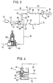
- a transverse control line 92 is connected to the pressure of the auxiliary circuit 50 via a hollow valve stem 90; 3, the transverse control line 92 leads to the trailer control valve 66.
- the trailer control valve 66 is in turn connected to the auxiliary circuit 50 via the T-piece 98.
- a control line shut-off valve 100 is integrated, which is opened by the transverse control line 92 only when the transverse control line 92 receives pressure at the coupling point A1, ie when the plug 60 is inserted into the socket 54 and then compressed air from the auxiliary circuit 50 can reach the control line 92 via the supply line shut-off valve 88 and the hollow valve stem 90.
- the control line shut-off valve 100 When the control line shut-off valve 100 is opened, it arrives via the trailer control valve 66 Control pressure in the control line 68, 74, 72 and ultimately to the trailer brake valve 78.
- This control pressure is derived from the pressure in the auxiliary circuit 50 and adjusted in size according to the pressures in the brake circuits 61, 62 and 64 of the towing vehicle by the trailer control valve.
- the pressure in the control line 72 controls the trailer brake valve 78 so that, depending on the size of the pressure in the control line 72, compressed air from the auxiliary circuit 50 can pass through the supply lines 58 and 56 into the trailing vehicle-side brake circuit 84, the pressure in the brake circuit 84 is dependent on the pressure in the brake circuits 61, 62, 64.
- the compressed air tank 82 ensures that compressed air is still available for the brake circuit 84 even if the supply line 58, 56 should be leaky.
- the supply line shut-off valve 88 ensures that when the plug 60 and the socket 54 are disconnected, no compressed air can escape from the auxiliary circuit 50.
- the control line shut-off valve 100 - controlled via the transverse control line 92 - ensures that when the socket 70 and 76 is disconnected, no compressed air from the auxiliary circuit 50 can escape through the control line 68 if in one of the brake circuits 61, 62, 64 for the purpose of braking the Towing vehicle is built up a brake pressure.
- a prerequisite for shutting off the control line shut-off valve 100 is that the plug 60 is also disconnected from the socket 54.
- the plugs 60 and 76 are only inserted into the sockets 54 and 70 after the coupling K has been engaged. Only then does the pressure prevailing in the auxiliary circuit 50 occur in the transverse control line 92.
- the connectors 60 and 76 are disconnected from the sockets 54 and 70 before the coupling K is released.
- the pressure in the transverse control line 92 therefore breaks down before the coupling K is released. From this sequence, which is maintained by the operating instructions and also to avoid the hose line sections 58 and 74 being torn off by the operating personnel: first coupling the coupling K and then inserting the plugs 60, 76 into the sockets 54, 70 or only pulling out the plugs 60, 76 from the sockets 54, 70 and then only release the coupling K, there is the possibility of using the pressure in the transverse control line 92 to actuate the tensioning device V.
- the line 40 is therefore tapped from the transverse control line 92, which leads via an overflow valve 104 to the compressed air cylinder 38 of the tensioning device V in FIG. 1.
- the overflow valve 104 is initially neglected in its effect.
- the plugs 60 and 76 are not yet inserted into the sockets 54 and 70, as explained above.
- the transverse control line 92 is therefore depressurized. No air pressure gets into the cylinder 38.
- the piston 36 therefore does not exert any tension-eliminating tensioning force on the push rod 30 and the prism 32.
- the coupling pin 12 can be moved downward through the drawbar eye 18 into the coupling position.
- the plugs 60 and 76 are first pulled from the sockets 54 and 70.
- the pressure in the transverse control line 92 thus collapses.
- the piston 36 in the cylinder 38 is depressurized.
- the tension between the coupling pin 12 and the towing eye 18 stops.
- the coupling pin 12 can be in its in without hindrance by the tensioning device V.
- Figure 1 shown disengaged position can be raised.
- the overflow valve 104 prevents the pressure in the transverse control line 92 from collapsing in the event of a leak in the line 40 to the left of the overflow valve 104. This pressure can only drop up to a certain value set on the overflow valve 104. If this value is undershot, the overflow valve 104 closes under the action of the closing spring 106.
- a backflow valve 108 is integrated in the overflow valve 104. This backflow valve 108 opens in FIG. 3 from left to right when the pressure in the transverse control line 92 is reduced, so that in the event of a pressure drop in the transverse control line 92 the pressure in the cylinder 38 is also reduced, which is necessary as described above.
- FIG. 5 shows a modification of the brake system according to FIG. 3. Analog parts are designated by the same reference numerals as in FIG. 3, each increased by the number 100.
- the transverse control line 92 of the embodiment according to FIG. 3 is not present and, accordingly, the control line shut-off valve 100 is also missing.
- the coupling point A2 is designed in such a way that the line 168 is automatically shut off when uncoupled in A2.
- the transverse control line 92 for controlling the tensioning device V is therefore not available.
- the coupling point A1 has remained the same as shown in FIG. 4.
- the line 192 receives compressed air and passes it on via the overflow valve 104 to the tensioning device V, an overflow valve 104 with backflow being arranged in the line 192 here as well.
Landscapes
- Engineering & Computer Science (AREA)
- Transportation (AREA)
- Mechanical Engineering (AREA)
- Regulating Braking Force (AREA)
- Indexing, Searching, Synchronizing, And The Amount Of Synchronization Travel Of Record Carriers (AREA)
- Valves And Accessory Devices For Braking Systems (AREA)
- Hydraulic Control Valves For Brake Systems (AREA)
Claims (10)
- Dispositif de rattrapage de jeu pour attelage de remorque (K) entre un véhicule tracteur (42) et un véhicule tracté, avec un appareil de retenue (V) retenant l'un contre l'autre deux éléments d'accouplement couplés (12, 18), lequel est inactif lors de l'opération de couplage et lors de l'opération de découplage,
caractérisé en ce que l'appareil de retenue (V) peut être activé en fonction du couplage d'au moins une liaison supplémentaire (54, 60, 58 ; 70, 76, 74) entre le véhicule tracteur (42) et le véhicule tracté, et peut être inactivé en fonction du découplage de la liaison supplémentaire (54, 60, 58 ; 70, 76, 74). - Dispositif selon la revendication 1,
caractérisé en ce que la liaison supplémentaire (54, 60, 58 ; 70, 76, 74) est une ligne d'alimentation de remorque ou fait partie d'une ligne de ce type. - Dispositif selon la revendication 2,
caractérisé en ce qu'il comprend un capteur d'activation, intégré dans un dispositif de couplage (A1, A2) de la ligne de liaison supplémentaire (54, 60, 58 ; 70, 76, 74), pouvant être activé et inactivé respectivement par le couplage et le découplage. - Dispositif selon l'une quelconque des revendications 1 ou 2, caractérisé en ce qu'un signal d'activation ou d'inactivation peut être dérivé d'une modification d'état, dans un système (B1) associé à la liaison supplémentaire (54, 60, 58 ; 70, 76, 74) considérée, laquelle modification d'état s'opère en tant que conséquence du couplage ou découplage de la liaison supplémentaire (54, 60, 58 ; 70, 76, 74) considérée.
- Dispositif selon la revendication 4,
caractérisé en ce que le signal d'activation ou d'inactivation peut être dérivé d'une modification d'état dans un système de freinage (B1, B2), ledit signal étant généré à la suite du couplage ou découplage d'au moins une ligne de freinage (58, 56 ; 74, 72) vers le véhicule tracté. - Dispositif selon la revendication 5,
caractérisé en ce que, dans le cas d'une installation de freinage pneumatique à deux lignes, avec une ligne de réserve (58, 56) et une ligne de commande (74, 72) vers le véhicule tracté, avec une vanne d'arrêt de ligne de réserve (88) réagissant respectivement au couplage ou découplage de la ligne de réserve (58, 56), avec une vanne d'arrêt de ligne de commande (100), réagissant également au couplage ou découplage de la ligne de réserve (58, 56), libérant ou bloquant la ligne de commande (76, 74) vers le véhicule tracté, et avec une ligne de commande transversale (92) de la vanne d'arrêt de la ligne de réserve (88) vers la vanne d'arrêt de la ligne de commande (100), le signal d'activation ou d'inactivation peut être dérivé de la ligne de commande transversale (92), laquelle exerce une pression ou est sans pression, en fonction respectivement du couplage ou du découplage de la ligne de réserve (58, 56). - Dispositif selon la revendication 6,
caractérisé en ce que le signal d'activation ou d'inactivation sert, sous la forme d'air comprimé dérivé de la ligne de commande transversale (92), à actionner ou commander l'appareil de retenue (V). - Dispositif selon la revendication 7,
caractérisé en ce que l'air comprimé, pour l'actionnement ou la commande de l'appareil de retenue (V), est dérivé de la ligne de commande transversale (92), par une soupape de décharge (104) avec écoulement de retour (108). - Dispositif selon la revendication 6,
caractérisé en ce que le signal d'activation ou d'inactivation peut être dérivé de la ligne de commande transversale (92) au moyen d'un capteur de pression et commande un système d'alimentation pour l'appareil de retenue (V). - Dispositif selon la revendication 5,
caractérisé en ce que, dans le cas d'une installation de freinage pneumatique à deux lignes avec une ligne de réserve (150) et une ligne de commande (168) vers le véhicule tracté, avec une vanne d'arrêt de ligne de réserve (en A1) réagissant respectivement au couplage ou découplage de la ligne de réserve, avec une vanne d'arrêt de ligne de commande (en A2) réagissant respectivement au couplage ou découplage de la ligne de commande (168), le signal d'activation ou d'inactivation est dérivé de la ligne de réserve (150), au lieu de la vanne d'arrêt de la ligne de réserve (en A1).
Priority Applications (1)
| Application Number | Priority Date | Filing Date | Title |
|---|---|---|---|
| AT91100699T ATE99607T1 (de) | 1990-02-06 | 1991-01-21 | Einrichtung zur spielausschaltung an anhaengerkupplungen stichwort: ansteuerung einer spielausschaltvorrichtung durch eine versorgungsleitung. |
Applications Claiming Priority (2)
| Application Number | Priority Date | Filing Date | Title |
|---|---|---|---|
| DE4003546 | 1990-02-06 | ||
| DE4003546A DE4003546A1 (de) | 1990-02-06 | 1990-02-06 | Einrichtung zur spielausschaltung an anhaengerkupplungen stichwort: "ansteuerung einer spielausschaltvorrichtung durch eine versorgungsleitung" |
Publications (2)
| Publication Number | Publication Date |
|---|---|
| EP0441158A1 EP0441158A1 (fr) | 1991-08-14 |
| EP0441158B1 true EP0441158B1 (fr) | 1994-01-05 |
Family
ID=6399565
Family Applications (1)
| Application Number | Title | Priority Date | Filing Date |
|---|---|---|---|
| EP91100699A Expired - Lifetime EP0441158B1 (fr) | 1990-02-06 | 1991-01-21 | Installation pour l'élimination du jeu dans des attelages de remorquage. Mot clé : commande de l'installation d'élimination du jeu par conduite d'alimentation |
Country Status (3)
| Country | Link |
|---|---|
| EP (1) | EP0441158B1 (fr) |
| AT (1) | ATE99607T1 (fr) |
| DE (2) | DE4003546A1 (fr) |
Cited By (1)
| Publication number | Priority date | Publication date | Assignee | Title |
|---|---|---|---|---|
| DE102020121793A1 (de) | 2020-08-19 | 2022-02-24 | Rühlicke GmbH | Anhängekupplung für Fahrzeuge |
Families Citing this family (1)
| Publication number | Priority date | Publication date | Assignee | Title |
|---|---|---|---|---|
| DE20002819U1 (de) | 2000-02-16 | 2000-05-25 | Sauermann, Hans, 86558 Hohenwart | Anhängerkupplung mit Spielbegrenzung |
Family Cites Families (9)
| Publication number | Priority date | Publication date | Assignee | Title |
|---|---|---|---|---|
| DE2458948C3 (de) * | 1974-12-12 | 1980-07-24 | Johann Rockinger Spezialfabrik Fuer Anhaengerkupplungen, 8000 Muenchen | Anhängerbolzenkupplung |
| DE2502944C3 (de) * | 1974-12-12 | 1981-08-20 | Johann Rockinger Spezialfabrik für Anhänger-Kupplungen, 8000 München | Vorrichtung zum Aus- und Einschalten des Spiels bei einer Anhängerkupplung |
| DE2529303C2 (de) * | 1975-01-24 | 1986-10-16 | Rockinger Spezialfabrik für Anhängerkupplungen GmbH & Co, 8000 München | Vorrichtung zum Aus- und Einschalten des Spiels zwischen den Kupplungsteilen einer Anhängerkupplung |
| DE2941482C2 (de) * | 1979-10-10 | 1987-02-12 | Fabeg Gmbh, 7518 Bretten | Mit einem Hilfsschaltkontakt versehenes Druckkontaktpaar für Kabelkupplungen von Fahrzeugen |
| DE3530817C2 (de) * | 1985-08-29 | 1994-05-19 | Wabco Vermoegensverwaltung | Deichselkraftmeßeinrichtung |
| FI78425C (fi) * | 1987-05-21 | 1989-08-10 | Hiab Multilift Oy | El- och tryckluftskoppling foer fordon, saosom mellan lastbil och slaepvagn. |
| DE3809434A1 (de) * | 1988-03-21 | 1989-10-05 | Rockinger Spezial Fab Joh | Vorrichtung zum ausschalten des spiels zwischen kupplungsteilen einer anhaengerkupplung (stichwort: vordruck im hydraulikvorrat) |
| DE3824225C2 (de) * | 1988-07-16 | 1997-08-21 | Ebern Fahrzeugtech Gmbh | Vorrichtung zum Spielausgleich für eine Nutzfahrzeug-Anhängerkupplung |
| DE3917918A1 (de) * | 1989-06-01 | 1990-12-06 | Rockinger Spezial Fab Joh | Anhaengerkupplung stichwort: spielausschaltungssteuerung durch aufwerfhebel |
-
1990
- 1990-02-06 DE DE4003546A patent/DE4003546A1/de not_active Withdrawn
-
1991
- 1991-01-21 AT AT91100699T patent/ATE99607T1/de not_active IP Right Cessation
- 1991-01-21 EP EP91100699A patent/EP0441158B1/fr not_active Expired - Lifetime
- 1991-01-21 DE DE91100699T patent/DE59100787D1/de not_active Expired - Fee Related
Cited By (2)
| Publication number | Priority date | Publication date | Assignee | Title |
|---|---|---|---|---|
| DE102020121793A1 (de) | 2020-08-19 | 2022-02-24 | Rühlicke GmbH | Anhängekupplung für Fahrzeuge |
| WO2022037947A1 (fr) | 2020-08-19 | 2022-02-24 | Rühlicke GmbH | Attelage de remorque pour véhicules |
Also Published As
| Publication number | Publication date |
|---|---|
| EP0441158A1 (fr) | 1991-08-14 |
| ATE99607T1 (de) | 1994-01-15 |
| DE4003546A1 (de) | 1991-08-08 |
| DE59100787D1 (de) | 1994-02-17 |
Similar Documents
| Publication | Publication Date | Title |
|---|---|---|
| EP4330110B1 (fr) | Attelage automatique de traction et procédé de dételage d'un attelage automatique de traction | |
| WO2011113853A1 (fr) | Système de frein de stationnement à commande électrique | |
| EP3971046B1 (fr) | Agencement de soupape d'un véhicule tracteur destiné à la commande d'une installation pneumatique de freinage d'un véhicule remorque et son procédé de commande | |
| WO2010004048A1 (fr) | Système automatique de freinage | |
| DE102020121087A1 (de) | Automatische Luftkupplung für ein Schienenfahrzeug und Verfahren zum Kuppeln von automatischen Luftkupplungen von Schienenfahrzeugen | |
| DE19706998A1 (de) | Kupplungsvorrichtung an einer ersten mobilen Einheit sowie zweite Einheit zum Ankoppeln an letztere | |
| EP0441158B1 (fr) | Installation pour l'élimination du jeu dans des attelages de remorquage. Mot clé : commande de l'installation d'élimination du jeu par conduite d'alimentation | |
| EP4155161A1 (fr) | Accouplement, notamment pour un véhicule ferroviaire | |
| DE69300585T2 (de) | Sicherheitsverriegelung zwischen Kupplung und Druckluftbremse. | |
| DE684684C (de) | Sicherheitsvorrichtung fuer Druckmittelbremseinrichtungen in Anhaengewagen | |
| EP3429925B1 (fr) | Véhicule de remorquage | |
| CH343433A (de) | Kupplungshäfte einer selbsttätigen Kupplung für Eisenbahn- und ähnliche Fahrzeuge | |
| DE813098C (de) | Anhaengevorrichtung fuer Kraftfahrzeuganhaenger | |
| AT391663B (de) | Halbautomatische auszugdeichsel mit auszugrohr fuer einen lkw-anhaenger | |
| EP1300315B1 (fr) | Système d'attelage pour véhicules ferroviaires | |
| DE102013010031A1 (de) | Kupplungskopfeinheit für ein Nutzfahrzeug und Verfahren zum Ankoppeln einer Versorgungsleitung und einer Steuerleitung an eine pneumatisch betriebene Bremsanlage | |
| DE1904843B2 (de) | Sicherheitskupplung zur verbindung einer hydraulischen bremsanlage eines anhaengers mit der eines zugfahrzeugs | |
| DE897052C (de) | Einrichtung zur Betaetigung der hydraulischen Bremse von Kraftfahrzeuganhaengern | |
| DE705773C (de) | Beim Auflaufen des Anhaengers auf den ziehenden Strassenkraftwagen wirkende Bremsvorrichtung | |
| DE1117425B (de) | Zweileitungs-Druckmittelbremsanlage fuer Wagenzuege | |
| EP4477507A1 (fr) | Semi-remorque avec sellette d'attelage avec fermeture actionnée par force extérieure | |
| CH674964A5 (fr) | ||
| DE822786C (de) | Einrichtung zum Sichern der Betriebsbereitschaft von durchgehenden Druckmittelbremsanlagen in Lastzuegen | |
| DE2305391A1 (de) | Vorrichtung zum automatischen kuppeln und entkuppeln von eisenbahnwaggons | |
| DE3240900C1 (de) | Kupplung für hydrauliche oder pneumatische Druckleitungen |
Legal Events
| Date | Code | Title | Description |
|---|---|---|---|
| PUAI | Public reference made under article 153(3) epc to a published international application that has entered the european phase |
Free format text: ORIGINAL CODE: 0009012 |
|
| AK | Designated contracting states |
Kind code of ref document: A1 Designated state(s): AT BE CH DE DK ES FR GB GR IT LI LU NL SE |
|
| 17P | Request for examination filed |
Effective date: 19911219 |
|
| 17Q | First examination report despatched |
Effective date: 19930205 |
|
| GRAA | (expected) grant |
Free format text: ORIGINAL CODE: 0009210 |
|
| AK | Designated contracting states |
Kind code of ref document: B1 Designated state(s): AT BE CH DE DK ES FR GB GR IT LI LU NL SE |
|
| PG25 | Lapsed in a contracting state [announced via postgrant information from national office to epo] |
Ref country code: GR Free format text: LAPSE BECAUSE OF FAILURE TO SUBMIT A TRANSLATION OF THE DESCRIPTION OR TO PAY THE FEE WITHIN THE PRESCRIBED TIME-LIMIT Effective date: 19940105 Ref country code: GB Effective date: 19940105 Ref country code: BE Effective date: 19940105 Ref country code: ES Free format text: THE PATENT HAS BEEN ANNULLED BY A DECISION OF A NATIONAL AUTHORITY Effective date: 19940105 Ref country code: DK Effective date: 19940105 |
|
| REF | Corresponds to: |
Ref document number: 99607 Country of ref document: AT Date of ref document: 19940115 Kind code of ref document: T |
|
| ITF | It: translation for a ep patent filed | ||
| PG25 | Lapsed in a contracting state [announced via postgrant information from national office to epo] |
Ref country code: AT Effective date: 19940121 |
|
| PG25 | Lapsed in a contracting state [announced via postgrant information from national office to epo] |
Ref country code: LI Effective date: 19940131 Ref country code: LU Free format text: LAPSE BECAUSE OF NON-PAYMENT OF DUE FEES Effective date: 19940131 Ref country code: CH Effective date: 19940131 |
|
| REF | Corresponds to: |
Ref document number: 59100787 Country of ref document: DE Date of ref document: 19940217 |
|
| ET | Fr: translation filed | ||
| GBV | Gb: ep patent (uk) treated as always having been void in accordance with gb section 77(7)/1977 [no translation filed] |
Effective date: 19940105 |
|
| REG | Reference to a national code |
Ref country code: CH Ref legal event code: PL |
|
| PLBE | No opposition filed within time limit |
Free format text: ORIGINAL CODE: 0009261 |
|
| STAA | Information on the status of an ep patent application or granted ep patent |
Free format text: STATUS: NO OPPOSITION FILED WITHIN TIME LIMIT |
|
| 26N | No opposition filed | ||
| EAL | Se: european patent in force in sweden |
Ref document number: 91100699.7 |
|
| EUG | Se: european patent has lapsed |
Ref document number: 91100699.7 |
|
| PGFP | Annual fee paid to national office [announced via postgrant information from national office to epo] |
Ref country code: FR Payment date: 20011227 Year of fee payment: 12 Ref country code: NL Payment date: 20011227 Year of fee payment: 12 |
|
| PGFP | Annual fee paid to national office [announced via postgrant information from national office to epo] |
Ref country code: SE Payment date: 20020102 Year of fee payment: 12 |
|
| PG25 | Lapsed in a contracting state [announced via postgrant information from national office to epo] |
Ref country code: SE Free format text: LAPSE BECAUSE OF NON-PAYMENT OF DUE FEES Effective date: 20030122 |
|
| PG25 | Lapsed in a contracting state [announced via postgrant information from national office to epo] |
Ref country code: NL Free format text: LAPSE BECAUSE OF NON-PAYMENT OF DUE FEES Effective date: 20030801 |
|
| EUG | Se: european patent has lapsed | ||
| PG25 | Lapsed in a contracting state [announced via postgrant information from national office to epo] |
Ref country code: FR Free format text: LAPSE BECAUSE OF NON-PAYMENT OF DUE FEES Effective date: 20030930 |
|
| NLV4 | Nl: lapsed or anulled due to non-payment of the annual fee |
Effective date: 20030801 |
|
| REG | Reference to a national code |
Ref country code: FR Ref legal event code: ST |
|
| PG25 | Lapsed in a contracting state [announced via postgrant information from national office to epo] |
Ref country code: IT Free format text: LAPSE BECAUSE OF NON-PAYMENT OF DUE FEES;WARNING: LAPSES OF ITALIAN PATENTS WITH EFFECTIVE DATE BEFORE 2007 MAY HAVE OCCURRED AT ANY TIME BEFORE 2007. THE CORRECT EFFECTIVE DATE MAY BE DIFFERENT FROM THE ONE RECORDED. Effective date: 20050121 |
|
| PGFP | Annual fee paid to national office [announced via postgrant information from national office to epo] |
Ref country code: DE Payment date: 20080122 Year of fee payment: 18 |
|
| PG25 | Lapsed in a contracting state [announced via postgrant information from national office to epo] |
Ref country code: DE Free format text: LAPSE BECAUSE OF NON-PAYMENT OF DUE FEES Effective date: 20090801 |