EP0441170A1 - Dispositif à briser les copeaux - Google Patents
Dispositif à briser les copeaux Download PDFInfo
- Publication number
- EP0441170A1 EP0441170A1 EP91100772A EP91100772A EP0441170A1 EP 0441170 A1 EP0441170 A1 EP 0441170A1 EP 91100772 A EP91100772 A EP 91100772A EP 91100772 A EP91100772 A EP 91100772A EP 0441170 A1 EP0441170 A1 EP 0441170A1
- Authority
- EP
- European Patent Office
- Prior art keywords
- crusher
- chips
- cutter
- workpiece
- rolls
- Prior art date
- Legal status (The legal status is an assumption and is not a legal conclusion. Google has not performed a legal analysis and makes no representation as to the accuracy of the status listed.)
- Granted
Links
- 239000002826 coolant Substances 0.000 claims abstract description 12
- 238000012544 monitoring process Methods 0.000 claims 2
- 238000003754 machining Methods 0.000 description 3
- 239000000463 material Substances 0.000 description 2
- 238000012986 modification Methods 0.000 description 1
- 230000004048 modification Effects 0.000 description 1
- 238000009877 rendering Methods 0.000 description 1
- 239000007787 solid Substances 0.000 description 1
Images


Classifications
-
- B—PERFORMING OPERATIONS; TRANSPORTING
- B23—MACHINE TOOLS; METAL-WORKING NOT OTHERWISE PROVIDED FOR
- B23B—TURNING; BORING
- B23B39/00—General-purpose boring or drilling machines or devices; Sets of boring and/or drilling machines
-
- B—PERFORMING OPERATIONS; TRANSPORTING
- B23—MACHINE TOOLS; METAL-WORKING NOT OTHERWISE PROVIDED FOR
- B23Q—DETAILS, COMPONENTS, OR ACCESSORIES FOR MACHINE TOOLS, e.g. ARRANGEMENTS FOR COPYING OR CONTROLLING; MACHINE TOOLS IN GENERAL CHARACTERISED BY THE CONSTRUCTION OF PARTICULAR DETAILS OR COMPONENTS; COMBINATIONS OR ASSOCIATIONS OF METAL-WORKING MACHINES, NOT DIRECTED TO A PARTICULAR RESULT
- B23Q11/00—Accessories fitted to machine tools for keeping tools or parts of the machine in good working condition or for cooling work; Safety devices specially combined with or arranged in, or specially adapted for use in connection with, machine tools
- B23Q11/0042—Devices for removing chips
- B23Q11/0057—Devices for removing chips outside the working area
Definitions
- the present invention relates to a device for skiving and roller burnishing a work piece.
- Skiving tools are usually used to accurately cut small quantities of material from the inner wall of a cylindrical hole.
- the skiving tool first cuts or shaves off a small amount of material, normally between 0.020 and 0.040 inch on the diameter, from the hole and then a roller burnishing tool, burnishes the hole to a smooth finish.
- chips may be in the form of a long flat ribbon-like string or small pieces. Strings of chips are difficult to handle. They may become entangled with each other or wrap around the chip conveyor, making it difficult for removal by the chip conveyor from the machine. It is also common for strings of chips to accumulate in the exit chamber of the device resulting in overloading, jamming or damage to the conveyor.
- skiving and roller burnishing devices are designed to produce chips having a small cross-section and length by using an assortment of various size interchangeable carbide chipbreakers. This is a major disadvantage when machining workpieces, such as hydraulic cylinders with oil port holes. These small chips can enter these openings and then fall into the rollers or pads on the skiving, roller burnishing tool, thus causing damage to both the tool and workpiece. When this occurs the workpiece is rendered unusable. Also a much higher coolant pressure is required to force this small chip ahead of the tool and from workpiece.
- the skiving and roller burnishing device is designed to cut a greater mass, up to 0.5 inch on diameter, at a faster rate than other cutting devices while still maintaining the precision machining related to skiving and roller burnishing.
- chips in the assignee's skiving and roller burnishing devices having a flat ribbon-like configuration, greater surface area and dimensions of 0.375 - 0.730 inch wide and 0.010 - 0.015 inch thick.
- the chips produced by the assignee's device must be in the form of long strings which cannot be easily broken by a carbide chipbreaker.
- the present invention is directed to a skiving and roller burnishing device for processing long, massive strings of chips.
- a crusher as an integral part of the skiving and roller burnishing device, the long strings of chips are easily manipulated and drawbacks previously encountered are avoided.
- the crusher is juxtapositioned beneath the cutter. In this way, the long strings of chips are forced from the workpiece by low pressure coolant directly into the crusher. After crushing, the chips are easily moved along a conveyor to a receptacle for holding the crushed chips.
- the crusher includes rolls for crushing the chips. Teeth have a lip and a groove are formed on each side of the rolls. The chips are caught by the lips within the grooves such that as the rolls rotate, the chips are grasped and pulled from the workpiece and burnishing tool and through the crusher.
- the chips are discharged from the cutter, they are directed by a chip delivery chute into the crusher.
- the chip delivery chute extends between the outer end of the workpiece and the entrance to the crusher.
- a deflector guides the chips into the crusher. It is preferably spaced from the cutter opposite the workpiece, angled upwardly from the crusher toward the cutter.
- a motor operates the crusher.
- a programmable controller is connected to a current sensing relay wired in series with the motor for sensing peak current and relaying the data for quickly stopping or reversing the device, protecting the crusher from damage.
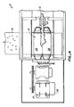
- Fig. 1 the overall structure of the skiving and roller burnishing device 2 will be described.
- Boring bar 4 moves through workpiece 6 such that cutter 8 skives the inner wall of workpiece 6.
- Strings of chips 10 flow through until the end 12 of workpiece 6 and are pulled to crusher 14.
- Crusher 14 is juxtaposed beneath end 12 of the workpiece and is formed as an integral part of skiving and roller burnishing device 2. From crusher 14, chips 10 are moved along conveyor 16 to a container 18, as seen in Fig. 3.
- a chip delivery chute 20 is disposed beneath cutter 8 between end 12 of work piece 6 and crusher 14, retaining and directing chips 10 into crusher 14. Chips 10 exit end 12 of workpiece 6 during the skiving operations.
- a deflector plate 22 is spaced laterally from cutter 8 adjacent to and above crusher 14, guiding chips 10 into crusher 14.
- a low pressure coolant 24 forces chips 10 into crusher 14 to begin the pulling action by crusher 14.
- crusher 14 includes a drive motor 15 for rotating rolls 26, 28.
- Rolls 26, 28 engage chips 10 as the rolls rotate in the direction of Arrows A, B, respectively.
- Each roll 26, has a plurality of teeth 30 for grasping and pulling chips 10 into crusher 14 for shredding.
- Teeth 30, as seen most clearly in Fig. 3, include a long, high-hooked lip 32 extending upwardly from rolls 26, 28 in the direction of rotation of the rolls.
- a groove 34 is formed between lip 32 end the outer periphery 36 of rolls 26, 28.
- chips 10 are produced and dispensed from workpiece 6, they are gripped within grooves 34 and pulled through the crusher 14 directly from the workpiece. After crushing, chips 10 continue on their path onto conveyor 16 and into container 18.
- Drive motor 13 includes a peak current sensing relay 38 disposed in series with the drive motor.
- the programmable controller can quickly stop or reverse the operation of crusher 14 in the event teeth 30 pull chips 10 too hard for machining conditions. Additionally, peak current sensing relay 38 protects crusher 14 from damage should foreign objects such as large solids be introduced into it.
- skiving and roller burnishing device 2 The operation of skiving and roller burnishing device 2 will now be described.
- Workpiece 6 is placed in position such that its inner surface receives boring bar 4 and cutter 8 for skiving operations.
- Chips 10 exit end 12 of workpiece 6 and are pulled through chip delivery chute 20 to crusher 14.
- Low pressure coolant 14 forces chips 10 toward deflector plate 22 and into rolls 26, 28 of crusher 14 to begin the pulling action by the crusher.
- Chips 10 are crushed by teeth 30, exit crusher 14 to conveyor 16 and into container 18.
- the present invention includes a programmable controller to provide a peak current sensing relay in series with the motor, other characteristics of the device may be monitored.
- An alternative chip delivery means may be employed, so long as the crusher is juxtaposed with the end of the workpiece and cutter.
Landscapes
- Engineering & Computer Science (AREA)
- Mechanical Engineering (AREA)
- Auxiliary Devices For Machine Tools (AREA)
- Crushing And Pulverization Processes (AREA)
- Percussive Tools And Related Accessories (AREA)
- Mechanisms For Operating Contacts (AREA)
- Fish Paste Products (AREA)
- Crushing And Grinding (AREA)
- Disintegrating Or Milling (AREA)
- Finish Polishing, Edge Sharpening, And Grinding By Specific Grinding Devices (AREA)
Priority Applications (1)
| Application Number | Priority Date | Filing Date | Title |
|---|---|---|---|
| AT91100772T ATE91930T1 (de) | 1990-02-06 | 1991-01-22 | Spaene-brecher. |
Applications Claiming Priority (2)
| Application Number | Priority Date | Filing Date | Title |
|---|---|---|---|
| US475654 | 1990-02-06 | ||
| US07/475,654 US5090628A (en) | 1990-02-06 | 1990-02-06 | Chip crusher |
Publications (2)
| Publication Number | Publication Date |
|---|---|
| EP0441170A1 true EP0441170A1 (fr) | 1991-08-14 |
| EP0441170B1 EP0441170B1 (fr) | 1993-07-28 |
Family
ID=23888536
Family Applications (1)
| Application Number | Title | Priority Date | Filing Date |
|---|---|---|---|
| EP91100772A Expired - Lifetime EP0441170B1 (fr) | 1990-02-06 | 1991-01-22 | Dispositif à briser les copeaux |
Country Status (7)
| Country | Link |
|---|---|
| US (1) | US5090628A (fr) |
| EP (1) | EP0441170B1 (fr) |
| JP (1) | JPH0755438B2 (fr) |
| KR (1) | KR100206613B1 (fr) |
| AT (1) | ATE91930T1 (fr) |
| DE (1) | DE69100186T2 (fr) |
| HK (1) | HK63394A (fr) |
Cited By (4)
| Publication number | Priority date | Publication date | Assignee | Title |
|---|---|---|---|---|
| WO1998034758A1 (fr) * | 1997-02-10 | 1998-08-13 | Filterwerk Mann+Hummel Gmbh | Dispositif de recuperation de refrigerants et de lubrifiants contenant des copeaux |
| US6126099A (en) * | 1996-09-27 | 2000-10-03 | Cae Beyss Gmbh | Pumping station for a cooling and lubricating fluid containing particulate matter |
| FR2803775A1 (fr) * | 2000-01-18 | 2001-07-20 | Omsat France | Dispositif de broyage et de pompage d'un melange de copeaux metalliques et de fluide de coupe |
| US6539827B2 (en) * | 2000-03-13 | 2003-04-01 | Japan Machine Tools, Corp. | Apparatus and method for discharging chips from a lathe |
Families Citing this family (12)
| Publication number | Priority date | Publication date | Assignee | Title |
|---|---|---|---|---|
| US5722604A (en) * | 1995-04-18 | 1998-03-03 | Dudley; Russell D. | Metal scrap shredder |
| US8827194B2 (en) * | 1999-04-01 | 2014-09-09 | Killgerm Group Limited | Fluorescent bulb compactor and mercury vapor recovery system |
| ATE501221T1 (de) | 2004-11-10 | 2011-03-15 | Toyo Boseki | Protonenleitendes polymer enthaltende zusammensetzung und herstellungsverfahren dafür, die protonenleitendes polymer enthaltende zusammensetzung enthaltende katalysatortinte und den katalysator enthaltende brennstoffzelle |
| DE102006007137B4 (de) * | 2006-02-16 | 2008-09-04 | Hegenscheidt-Mfd Gmbh & Co. Kg | Mobile Radsatzbearbeitungseinrichtung |
| JP2014079860A (ja) * | 2012-10-17 | 2014-05-08 | Disco Abrasive Syst Ltd | 加工装置 |
| JP2016030309A (ja) * | 2014-07-28 | 2016-03-07 | 株式会社デンソー | 切削屑処理装置及びそれを備えた切削加工機 |
| US10071382B1 (en) * | 2017-07-19 | 2018-09-11 | Phiston Technologies, Inc. | Solid state drive disintegrator |
| US11400457B2 (en) * | 2018-07-20 | 2022-08-02 | Phiston Technologies, Inc. | Solid state drive media destroyer |
| US20200094363A1 (en) * | 2018-09-20 | 2020-03-26 | Tejas Tubular Products, Inc. | Apparatus for Removing Turnings from a Workpiece Being Machined |
| US10657345B1 (en) | 2019-07-02 | 2020-05-19 | Phiston Technologies, Inc. | Media destruction verification apparatus |
| CN111889490B (zh) * | 2020-08-05 | 2021-08-24 | 马鞍山市新桥工业设计有限公司 | 一种具有压缩结构的机床加工用废料收集装置 |
| CN112207610A (zh) * | 2020-09-27 | 2021-01-12 | 董苏倩 | 一种机床加工专用废屑预处理一体机及其使用方法 |
Citations (3)
| Publication number | Priority date | Publication date | Assignee | Title |
|---|---|---|---|---|
| GB707551A (en) * | 1950-12-30 | 1954-04-21 | Samuel Bailey Wright | Method of and apparatus for breaking up a length of swarf generated in a machine tool |
| DE1477731A1 (de) * | 1964-12-04 | 1969-03-27 | Siemens Ag | Einrichtung an spanabhebenden Werkzeugmaschinen |
| DE2048260A1 (de) * | 1970-10-01 | 1972-04-06 | Dalferth G | Vorrichtung zur selbsttätigen Abfuh rung und Zerkleinerung von langfaserigen Spanen bei der spangebenden Bearbeitung |
Family Cites Families (12)
| Publication number | Priority date | Publication date | Assignee | Title |
|---|---|---|---|---|
| US2453008A (en) * | 1948-11-02 | fowler | ||
| US2418990A (en) * | 1944-01-29 | 1947-04-15 | Pulverizing Machinery Company | Combined chipping machine and impact mill |
| JPS514675A (en) * | 1974-07-01 | 1976-01-14 | Sumitomo Electric Industries | Gasuenshinbunrikyo kaitendotanban |
| US4377259A (en) * | 1980-03-21 | 1983-03-22 | Reclamet, Inc. | Chip and turnings separator and crusher |
| US4556922A (en) * | 1981-09-08 | 1985-12-03 | U.S. Philips Corporation | VCR With improved tape threading and guiding |
| US4793561A (en) * | 1982-05-24 | 1988-12-27 | Mac Corporation Of America | Speed-responsive reversing hydraulic drive for rotary shredder |
| JPS591627A (ja) * | 1982-06-24 | 1984-01-07 | Nippon Steel Corp | 連続鋳造鋳片の熱間割れ防止法 |
| AU552900B2 (en) * | 1983-09-09 | 1986-06-26 | Yoshida Kogyo K.K. | Chopping runners and sprues |
| SU1250324A1 (ru) * | 1984-10-09 | 1986-08-15 | Предприятие П/Я В-2548 | Устройство дл измельчени металлической стружки |
| DE3541984A1 (de) * | 1985-11-28 | 1987-06-04 | Breyell Metall | Vorrichtung zum zerkleinern von band- bzw. streifenfoermigen abfaellen aus z.b. stahlblech |
| DE3637612A1 (de) * | 1986-11-05 | 1988-05-19 | Karl Hehl | Kunststoff-spritzgiessmaschine mit eingebauter zerkleinerungseinrichtung fuer die anguesse |
| GB2215235B (en) * | 1988-02-25 | 1992-02-05 | Ofrex Group Holdings Plc | Improvements relating to shredding machines |
-
1990
- 1990-02-06 US US07/475,654 patent/US5090628A/en not_active Expired - Lifetime
-
1991
- 1991-01-22 DE DE91100772T patent/DE69100186T2/de not_active Expired - Lifetime
- 1991-01-22 EP EP91100772A patent/EP0441170B1/fr not_active Expired - Lifetime
- 1991-01-22 AT AT91100772T patent/ATE91930T1/de not_active IP Right Cessation
- 1991-02-06 JP JP3035127A patent/JPH0755438B2/ja not_active Expired - Fee Related
- 1991-02-06 KR KR1019910002002A patent/KR100206613B1/ko not_active Expired - Lifetime
-
1994
- 1994-06-30 HK HK63394A patent/HK63394A/en not_active IP Right Cessation
Patent Citations (3)
| Publication number | Priority date | Publication date | Assignee | Title |
|---|---|---|---|---|
| GB707551A (en) * | 1950-12-30 | 1954-04-21 | Samuel Bailey Wright | Method of and apparatus for breaking up a length of swarf generated in a machine tool |
| DE1477731A1 (de) * | 1964-12-04 | 1969-03-27 | Siemens Ag | Einrichtung an spanabhebenden Werkzeugmaschinen |
| DE2048260A1 (de) * | 1970-10-01 | 1972-04-06 | Dalferth G | Vorrichtung zur selbsttätigen Abfuh rung und Zerkleinerung von langfaserigen Spanen bei der spangebenden Bearbeitung |
Non-Patent Citations (3)
| Title |
|---|
| SOVIET INVENTIONS ILLUSTRA- TED, P,Q sections, week 8647, January 7, 1987 DERWENT PUBLICATIONS LTD., London, P-56, & SU-A-1 140 363 (MALA) * |
| SOVIET INVENTIONS ILLUSTRA- TED, P,Q sections, week 8709, April 15, 1987 DERWENT PUBLICATIONS LTD., London, P-54, & SU-A-1 242 308 (DEUY) * |
| SOVIET INVENTIONS ILLUSTRA- TED, P,Q sections, week C 33, September 24, 1980 DERWENT PUBLICATIONS LTD., London, P-54, & SU-A-706 197 (NIKO) * |
Cited By (5)
| Publication number | Priority date | Publication date | Assignee | Title |
|---|---|---|---|---|
| US6126099A (en) * | 1996-09-27 | 2000-10-03 | Cae Beyss Gmbh | Pumping station for a cooling and lubricating fluid containing particulate matter |
| WO1998034758A1 (fr) * | 1997-02-10 | 1998-08-13 | Filterwerk Mann+Hummel Gmbh | Dispositif de recuperation de refrigerants et de lubrifiants contenant des copeaux |
| FR2803775A1 (fr) * | 2000-01-18 | 2001-07-20 | Omsat France | Dispositif de broyage et de pompage d'un melange de copeaux metalliques et de fluide de coupe |
| EP1125680A1 (fr) * | 2000-01-18 | 2001-08-22 | Ecofluide | Dispositif de broyage et de pompage d'un mélange de copeaux métalliques et de fluide de coupe |
| US6539827B2 (en) * | 2000-03-13 | 2003-04-01 | Japan Machine Tools, Corp. | Apparatus and method for discharging chips from a lathe |
Also Published As
| Publication number | Publication date |
|---|---|
| EP0441170B1 (fr) | 1993-07-28 |
| JPH0755438B2 (ja) | 1995-06-14 |
| HK63394A (en) | 1994-07-01 |
| ATE91930T1 (de) | 1993-08-15 |
| KR100206613B1 (ko) | 1999-07-01 |
| KR910015354A (ko) | 1991-09-30 |
| DE69100186T2 (de) | 1993-11-11 |
| JPH0516055A (ja) | 1993-01-26 |
| DE69100186D1 (de) | 1993-09-02 |
| US5090628A (en) | 1992-02-25 |
Similar Documents
| Publication | Publication Date | Title |
|---|---|---|
| US5090628A (en) | Chip crusher | |
| US5215135A (en) | Pellitizer methods and apparatus | |
| CA1188603A (fr) | Methode pour interrompre l'alimentation en bois d'une dechiqueteuse portable | |
| EP0738560B1 (fr) | Appareil de broyage, manipulation, et transport | |
| IL101742A (en) | A mole that forms a chip | |
| CS238361B2 (en) | Wire or strip electrode separation equipment in electro-erosion machining device | |
| DE19851054C2 (de) | Zerkleinerungsvorrichtung zum Schnitzeln und Schreddern von Abfallmaterial und Verfahren hierzu | |
| GB2365803A (en) | Fragmentiser | |
| DE102021126898B3 (de) | Zerkleinerer zum Zerkleinern von Spänen | |
| JP4825547B2 (ja) | 切り粉切断圧縮装置 | |
| JP5221927B2 (ja) | 破砕処理装置 | |
| DE1188095B (de) | Verfahren zur Gewinnung von Schrott | |
| JP2005296795A (ja) | 破砕処理装置 | |
| CN1069686A (zh) | 切屑破碎机 | |
| EP1238736B1 (fr) | Dispositif d'évacuation et de briser de copeaux | |
| RU192840U1 (ru) | Концевая фреза | |
| CN113084663A (zh) | 一种磨尖机 | |
| JPH07195251A (ja) | エンドミル加工における切屑吸引装置 | |
| US3184827A (en) | Trepanning tool for trepanning tapered metal shapes | |
| DE927062C (de) | Vorrichtung zum Zerkleinern der beim Gewindeschneiden mit Hartmetall-Einzahnstaehlen anfallenden Spaene | |
| JP3025251U (ja) | ねじれ流体供給穴付きエンドミル | |
| KR100523098B1 (ko) | 사이드트리머의 절단칩 권취장치 | |
| JP2720537B2 (ja) | 転削工具 | |
| JPH0742679U (ja) | 切屑処理装置 | |
| GB2055067A (en) | Peeling metal strip from a workpiece |
Legal Events
| Date | Code | Title | Description |
|---|---|---|---|
| PUAI | Public reference made under article 153(3) epc to a published international application that has entered the european phase |
Free format text: ORIGINAL CODE: 0009012 |
|
| AK | Designated contracting states |
Kind code of ref document: A1 Designated state(s): AT BE CH DE DK ES FR GB GR IT LI LU NL SE |
|
| 17P | Request for examination filed |
Effective date: 19910703 |
|
| 17Q | First examination report despatched |
Effective date: 19920720 |
|
| ITF | It: translation for a ep patent filed | ||
| GRAA | (expected) grant |
Free format text: ORIGINAL CODE: 0009210 |
|
| AK | Designated contracting states |
Kind code of ref document: B1 Designated state(s): AT BE CH DE DK ES FR GB GR IT LI LU NL SE |
|
| PG25 | Lapsed in a contracting state [announced via postgrant information from national office to epo] |
Ref country code: FR Effective date: 19930728 Ref country code: CH Effective date: 19930728 Ref country code: BE Effective date: 19930728 Ref country code: GR Free format text: LAPSE BECAUSE OF FAILURE TO SUBMIT A TRANSLATION OF THE DESCRIPTION OR TO PAY THE FEE WITHIN THE PRESCRIBED TIME-LIMIT Effective date: 19930728 Ref country code: NL Effective date: 19930728 Ref country code: ES Free format text: THE PATENT HAS BEEN ANNULLED BY A DECISION OF A NATIONAL AUTHORITY Effective date: 19930728 Ref country code: SE Effective date: 19930728 Ref country code: LI Effective date: 19930728 Ref country code: DK Effective date: 19930728 Ref country code: AT Effective date: 19930728 |
|
| REF | Corresponds to: |
Ref document number: 91930 Country of ref document: AT Date of ref document: 19930815 Kind code of ref document: T |
|
| REF | Corresponds to: |
Ref document number: 69100186 Country of ref document: DE Date of ref document: 19930902 |
|
| REG | Reference to a national code |
Ref country code: CH Ref legal event code: PL |
|
| EN | Fr: translation not filed | ||
| NLV1 | Nl: lapsed or annulled due to failure to fulfill the requirements of art. 29p and 29m of the patents act | ||
| PG25 | Lapsed in a contracting state [announced via postgrant information from national office to epo] |
Ref country code: LU Free format text: LAPSE BECAUSE OF NON-PAYMENT OF DUE FEES Effective date: 19940131 |
|
| PLBE | No opposition filed within time limit |
Free format text: ORIGINAL CODE: 0009261 |
|
| STAA | Information on the status of an ep patent application or granted ep patent |
Free format text: STATUS: NO OPPOSITION FILED WITHIN TIME LIMIT |
|
| 26N | No opposition filed | ||
| REG | Reference to a national code |
Ref country code: GB Ref legal event code: IF02 |
|
| PGFP | Annual fee paid to national office [announced via postgrant information from national office to epo] |
Ref country code: GB Payment date: 20091211 Year of fee payment: 20 |
|
| PGFP | Annual fee paid to national office [announced via postgrant information from national office to epo] |
Ref country code: IT Payment date: 20100114 Year of fee payment: 20 |
|
| PGFP | Annual fee paid to national office [announced via postgrant information from national office to epo] |
Ref country code: DE Payment date: 20100129 Year of fee payment: 20 |
|
| REG | Reference to a national code |
Ref country code: GB Ref legal event code: PE20 Expiry date: 20110121 |
|
| PG25 | Lapsed in a contracting state [announced via postgrant information from national office to epo] |
Ref country code: GB Free format text: LAPSE BECAUSE OF EXPIRATION OF PROTECTION Effective date: 20110121 |
|
| PG25 | Lapsed in a contracting state [announced via postgrant information from national office to epo] |
Ref country code: DE Free format text: LAPSE BECAUSE OF EXPIRATION OF PROTECTION Effective date: 20110122 |