EP0441230A1 - Appareil pour la séparation par pressurisation et flotation - Google Patents
Appareil pour la séparation par pressurisation et flotation Download PDFInfo
- Publication number
- EP0441230A1 EP0441230A1 EP91101161A EP91101161A EP0441230A1 EP 0441230 A1 EP0441230 A1 EP 0441230A1 EP 91101161 A EP91101161 A EP 91101161A EP 91101161 A EP91101161 A EP 91101161A EP 0441230 A1 EP0441230 A1 EP 0441230A1
- Authority
- EP
- European Patent Office
- Prior art keywords
- water
- tank
- flotables
- processed
- flotation
- Prior art date
- Legal status (The legal status is an assumption and is not a legal conclusion. Google has not performed a legal analysis and makes no representation as to the accuracy of the status listed.)
- Granted
Links
- 238000005188 flotation Methods 0.000 title claims abstract description 45
- 238000000926 separation method Methods 0.000 title claims abstract description 24
- 239000002245 particle Substances 0.000 claims abstract description 23
- XLYOFNOQVPJJNP-UHFFFAOYSA-N water Substances O XLYOFNOQVPJJNP-UHFFFAOYSA-N 0.000 claims description 131
- 238000010521 absorption reaction Methods 0.000 claims description 16
- 239000007787 solid Substances 0.000 abstract description 8
- 239000007788 liquid Substances 0.000 abstract 7
- 239000013049 sediment Substances 0.000 description 7
- 230000014759 maintenance of location Effects 0.000 description 4
- 238000013019 agitation Methods 0.000 description 3
- 238000007599 discharging Methods 0.000 description 3
- 230000005484 gravity Effects 0.000 description 3
- 238000000034 method Methods 0.000 description 3
- 239000000203 mixture Substances 0.000 description 3
- 239000013043 chemical agent Substances 0.000 description 2
- 239000008394 flocculating agent Substances 0.000 description 1
- 238000005192 partition Methods 0.000 description 1
- 238000011084 recovery Methods 0.000 description 1
- 238000007789 sealing Methods 0.000 description 1
- 238000003756 stirring Methods 0.000 description 1
Images


Classifications
-
- B—PERFORMING OPERATIONS; TRANSPORTING
- B03—SEPARATION OF SOLID MATERIALS USING LIQUIDS OR USING PNEUMATIC TABLES OR JIGS; MAGNETIC OR ELECTROSTATIC SEPARATION OF SOLID MATERIALS FROM SOLID MATERIALS OR FLUIDS; SEPARATION BY HIGH-VOLTAGE ELECTRIC FIELDS
- B03D—FLOTATION; DIFFERENTIAL SEDIMENTATION
- B03D1/00—Flotation
- B03D1/02—Froth-flotation processes
- B03D1/04—Froth-flotation processes by varying ambient atmospheric pressure
-
- B—PERFORMING OPERATIONS; TRANSPORTING
- B03—SEPARATION OF SOLID MATERIALS USING LIQUIDS OR USING PNEUMATIC TABLES OR JIGS; MAGNETIC OR ELECTROSTATIC SEPARATION OF SOLID MATERIALS FROM SOLID MATERIALS OR FLUIDS; SEPARATION BY HIGH-VOLTAGE ELECTRIC FIELDS
- B03D—FLOTATION; DIFFERENTIAL SEDIMENTATION
- B03D1/00—Flotation
- B03D1/14—Flotation machines
- B03D1/1418—Flotation machines using centrifugal forces
-
- B—PERFORMING OPERATIONS; TRANSPORTING
- B03—SEPARATION OF SOLID MATERIALS USING LIQUIDS OR USING PNEUMATIC TABLES OR JIGS; MAGNETIC OR ELECTROSTATIC SEPARATION OF SOLID MATERIALS FROM SOLID MATERIALS OR FLUIDS; SEPARATION BY HIGH-VOLTAGE ELECTRIC FIELDS
- B03D—FLOTATION; DIFFERENTIAL SEDIMENTATION
- B03D1/00—Flotation
- B03D1/14—Flotation machines
- B03D1/1412—Flotation machines with baffles, e.g. at the wall for redirecting settling solids
-
- B—PERFORMING OPERATIONS; TRANSPORTING
- B03—SEPARATION OF SOLID MATERIALS USING LIQUIDS OR USING PNEUMATIC TABLES OR JIGS; MAGNETIC OR ELECTROSTATIC SEPARATION OF SOLID MATERIALS FROM SOLID MATERIALS OR FLUIDS; SEPARATION BY HIGH-VOLTAGE ELECTRIC FIELDS
- B03D—FLOTATION; DIFFERENTIAL SEDIMENTATION
- B03D1/00—Flotation
- B03D1/14—Flotation machines
- B03D1/1431—Dissolved air flotation machines
-
- B—PERFORMING OPERATIONS; TRANSPORTING
- B03—SEPARATION OF SOLID MATERIALS USING LIQUIDS OR USING PNEUMATIC TABLES OR JIGS; MAGNETIC OR ELECTROSTATIC SEPARATION OF SOLID MATERIALS FROM SOLID MATERIALS OR FLUIDS; SEPARATION BY HIGH-VOLTAGE ELECTRIC FIELDS
- B03D—FLOTATION; DIFFERENTIAL SEDIMENTATION
- B03D1/00—Flotation
- B03D1/14—Flotation machines
- B03D1/1443—Feed or discharge mechanisms for flotation tanks
- B03D1/1462—Discharge mechanisms for the froth
-
- B—PERFORMING OPERATIONS; TRANSPORTING
- B03—SEPARATION OF SOLID MATERIALS USING LIQUIDS OR USING PNEUMATIC TABLES OR JIGS; MAGNETIC OR ELECTROSTATIC SEPARATION OF SOLID MATERIALS FROM SOLID MATERIALS OR FLUIDS; SEPARATION BY HIGH-VOLTAGE ELECTRIC FIELDS
- B03D—FLOTATION; DIFFERENTIAL SEDIMENTATION
- B03D1/00—Flotation
- B03D1/14—Flotation machines
- B03D1/24—Pneumatic
-
- C—CHEMISTRY; METALLURGY
- C02—TREATMENT OF WATER, WASTE WATER, SEWAGE, OR SLUDGE
- C02F—TREATMENT OF WATER, WASTE WATER, SEWAGE, OR SLUDGE
- C02F1/00—Treatment of water, waste water, or sewage
- C02F1/24—Treatment of water, waste water, or sewage by flotation
-
- B—PERFORMING OPERATIONS; TRANSPORTING
- B03—SEPARATION OF SOLID MATERIALS USING LIQUIDS OR USING PNEUMATIC TABLES OR JIGS; MAGNETIC OR ELECTROSTATIC SEPARATION OF SOLID MATERIALS FROM SOLID MATERIALS OR FLUIDS; SEPARATION BY HIGH-VOLTAGE ELECTRIC FIELDS
- B03D—FLOTATION; DIFFERENTIAL SEDIMENTATION
- B03D1/00—Flotation
- B03D1/02—Froth-flotation processes
- B03D1/028—Control and monitoring of flotation processes; computer models therefor
-
- B—PERFORMING OPERATIONS; TRANSPORTING
- B03—SEPARATION OF SOLID MATERIALS USING LIQUIDS OR USING PNEUMATIC TABLES OR JIGS; MAGNETIC OR ELECTROSTATIC SEPARATION OF SOLID MATERIALS FROM SOLID MATERIALS OR FLUIDS; SEPARATION BY HIGH-VOLTAGE ELECTRIC FIELDS
- B03D—FLOTATION; DIFFERENTIAL SEDIMENTATION
- B03D1/00—Flotation
- B03D1/14—Flotation machines
- B03D1/1443—Feed or discharge mechanisms for flotation tanks
- B03D1/1468—Discharge mechanisms for the sediments
Definitions
- the present invention relates to an apparatus for separation by pressurization and flotation, and more particularly, to an apparatus for separation of solid particles from water to be processed, by supplying the pressurized water to a flotation tank where air bubbles attach to the solid particles suspended in the water to float them on the surface.
- the water to be processed which contain the solids as suspended particles is pressurized so as to dissolve air in the water, and when the pressurized water is put back under a normal pressure, the dissolved air emerges as microscopic air bubbles which attach to the particles in the water and float the particles on the surface for recovery.
- JP(B2)P56-23668 US 4,022,696 ⁇ DE(C2)2,713,088) and Japanese Patent Pub. No. 58-23153 (US 4,184,967 ⁇ DE (C2)2,925,269).
- the water is supplied into the water in a flotation/separation tank within which the solids are separated from the water.
- Fig. 10 shows a typical apparatus according to the prior art, including a flotation tank 1 and an outlet pipe 3 for the water to be processed mounted in the tank 1.
- a processed water catcher pipe 3 is disposed near the bottom of the tank 1 so as to discharge the processed water.
- a tank 4 for the processed water houses a water level pipe 5 connected to the water catcher pipe 3. The upper level of the water in the pipe 5 determinens the water level in the flotation tank 1.
- a tank 6 containing the original water to be processed is connected by a pump 9 to a mixer 7.
- a pressurizing tank 8 is connected via a pump 10 to the tank 4 on one hand, and on the other to the mixer 7 which is connected to the outlet pipe 2.
- a skim rake 12 for skimming flotables on the surface in the tank 1, is connected to the drive shaft for a motor 13 and mounted rotatable thereby.
- An outlet 14 is provided in the upper part of the tank 1 to discharge the flotables.
- a rake means 15 is provided to rake sediments in the tank 1.
- the original water to be processed stored in the tank 6 is supplied by the pump 9 to the mixer 7. Meanwhile, the processed water is partly supplied by the pump 10 to the pressurizing tank 8, where the water is pressurized together with the air coming from the intake 11, and then supplied to the mixer 7.
- the original water reaching the mixer 7 is mixed with the processed, pressurized water, and the mixture is fed to the outlet pipe 2 under a pressurized condition.
- the flotables on the surface in the tank are skimmed off by the skimmer rake 12 and discharged from the outlet 14.
- the processed water is supplied to the tank 4, from which the water is partly discharged and partly pressurized to be supplied again to the tank 1 for the separation process.
- An object of the present invention is to provide a separation apparatus by supplying the water to be processed onto the surface in the tank so as to prevent turbulence in the tank and remarkably enhance the processing capacity.
- Another object of the present invention is to provide a separation apparatus which can supply the water to the surface at an angle appropriate for the property of the water, by providing an improved guide plate which is adjustable in the mounting angle.
- the present invention comprises a flotation tank, a mixing chamber for mixing the original water to be processed with the pressurized water and supplying the mixture from the bottom, a supply means for supplying the mixed water onto the water surface in the tank while the mixed water contains suspended particles attached to air bubbles, a catcher means for the processed water provided at the bottom of the tank, a removal means for removing flotables separated from the water, and a means for keeping the water in the tank at a predetermined level.
- the present invention further comprises means for supplying the water to be processed to the surface at an adjustable angle.
- the original water to be processed and the pressurized water are introduced to the bottom of the mixing chamber and mixed therein, and because the mixing chamber is under atmospheric pressure, the mixed water gradually flows upward while producing air bubbles.
- the air bubbles attach themselves to the suspended particles in the mixed water and flow from the upper part of the mixing chamber onto the surface in the tank.
- the flotables are skimmed by the skimmer rake and absorbed by a absorption cup operated by a discharge pump.
- the water to be processed is supplied onto the surface, there occurs no turbulence in the tank caused by the water supplied.
- the retention time for processing in the tank can be reduced, resulting in remarkable increase in the amount of water to be processed per unit cubic volume of the tank.
- the guide plate adjustable in its mounting angle can optionally change the angle by which the water is supplied to the surface, according to the property of the water.
- the water may be supplied somewhat at a distance from the surface or at a position abutting on the surface.
- the present invention can reduce the retention time of the water in the tank, thereby remarkably increasing the amount of water to be processed per unit cubic volume of the tank.
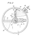
- a flotation tank 20 is formed as a cylindrical shape, at the central portion of which is positioned a cylindrical mixing chamber 21 having two inlets at the bottom; an inlet 22 for the original water to be procesed and another inlet 23 for pressurized water.
- the inlet 22 is connected to a tank 24 housing the original water while the inlet 23 is connected to a pressurizing tank 25.
- the tank 24 containing the original water to be processed is connected to the inlet 22 via a pump 26, a flow adjusting valve 27, and a flow meter 28.
- a pump 26 a flow adjusting valve 27
- a flow meter 28 a flow meter 28
- a processed water tank 29 from which the processed water is taken out to be pressurized with air by a pump 30 and stored in the tank 25.
- a pressure reducing valve 31 Between the inlet 23 and the tank 25, a pressure reducing valve 31, a flow meter 32 and a flow adjusting valve 33 are provided. Further, between the pressure reducing valve 31 and the flow meter 32, is connected by a supply pump 35 a tank 34 for chemical agents, such as flocculating agents.
- Reference numeral 36 indicates a stirring means.
- Reference numeral 37 is an air intake provided between the tank 29 and the pump 30, for adjustment of the flow of the processed water.
- a upside-down cup-shaped cylinder 38 is mounted rotatable at the upper end of the mixing chamber 21.
- the rotatable cylinder 38 has an outlet 39 to which is connected a horizontal distribution pipe 40.
- the distribution pipe 40 is formed with a distribution slit 41 opening along the pipe 40.
- the water to be processed, namely the mixture of the original water to be processed and the pressurized water, coming from the outlet 39 is distributed by the pipe 40 onto the surface in the tank 20.
- a rotatable shaft 43 projecting vertically through a frame 42 covering the upper part of the flotation tank 20 is mounted to the cylinder 38.
- a rotating device 44 mounted on the frame 42 has a driving gear 45 associated by a chain 47 with a driven gear 46 mounted at the upper part of the drive shaft 43.
- a sealing means 48 Between the mixing chamber 21 and the rotatable cylinder 38, there is provided a sealing means 48.
- skimmer rakes 50 Inside the tank 20, there are skimmer rakes 50 and an absorption cup 51. Flotables on the surface are skimmed off by the skimmer rakes 50 and absorbed by the absorption cup 51.
- the skimmer rakes 50 are mounted to a mounting bar 52 fixed at the cylinder 38, and are inclined to the absorption cup 51 so that the flotables gather at the cup 51.
- rakes 54 for sediments are provided at the bottom of the tank 20 to rake sediments on the bottom toward an outlet 53.
- the rakes 54 are disposed radially of the mixing chamber 21 and connected to the cylinder 38 to be rotated thereby.
- Partition plates 55 are mounted near the bottom of the tank 20, and under the plates, there is a water catcher pipe 56 connected to a gauge pipe 57 standing up in the tank 29 and having an opening therein.
- the processed water tank 29 is formed with a discharge pipe 58.
- a pump 59 for discharging the flotables is mounted to the frame 41 and connected to the absorpotion cup 51 via an absorption pipe 60 and a universal joint 61.
- the outlet 53 for the sediments is connected with a discharge pipe 62, which is adapted to open/close by a valve 63 and is usually closed.
- the distribution pipe 40 is mounted in the radial direction of the flotation tank 20 and adapted to rotate clockwise by the rotating device 44.
- the distribution pipe 40 is followed in the rotational direction by the skimmer rakes 50 and the absorption cup 51.
- the skimmer rakes 50 are slanted forward in the rotational direction so that they scrape up the flotables 49 toward the absorption cup 51.
- the processed water in the tank 29 is pressurized by a pump 30 with air whose weight ratio to the particles in the original water to be processed is about 1/10 to 1/50, to 2 to 4 kg/cm2, for example, and then the water is supplied to the tank 25. Consequently, a large amount of air is dissolved in the water in the tank 25.
- the air is introduced to the intake side of the pump 30 and pressurized together with the water to be processed, so as to eliminate air compressing means. It may be possible to pressurize the water to be processed and air separately and supply them to the tank 25.
- the water to be processed stored in the tank 25 is controlled by the flow adjusting valve 33, and supplied through the pressure reducing valve 31 and the inlet 23 to the bottom of the mixing chamber 21, together with the chemical agent fed from the tank 34 via the pump 35.
- the original water to be processed stored in the tank 24 is controlled by the pump 26 and the flow adjusting valve 27, and fed through the inlet 22 to the bottom of the mixing chamber 21, where the original water to be processed is mixed with the pressurized water and gradualy rises.
- the mixing chamber is at an atmospheric pressure, the air dissolved in the high-pressure water supplied from the inlet 23 emerges as microscopic air bubbles and the bubbles attach to the particles contained in the water.
- the mixed water to be processed reaches the upper end of the mixing chamber 21 and flows out from the outlet 39 of the cylinder 38, together with air bubbles attaching to the particles. Then the water is supplied from the slit 41 formed in the clock-wise rotating distribution pipe 40 and uniformly distributed onto the water surface in the tank 20.
- the particles in the water decrease in its specific gravity whereby the particles separate from the water and float on the surface.
- the skimmer rakes 50 rotating with the distribution pipe 40 skim off the flotables and carry them to the absorption cup 51 to be absorbed and discharged thereby.
- the mixing chamber 21 in which air bubbles attach to the solid particles in the water to be processed is substantially separated from the flotation tank 20 and the water from the mixing chamber 21 is supplied from above the surface in the tank 20. Therefore, as the water to be processed is supplied, there occurs no such agitation of the water as seen in the prior art but only sinking phenomenan with the air bubbles sinking to an extremely small extent.
- the flotation tank 20 may be of a water depth necessary for such sinking, and furthermore, the tank may have minimun required area because the water is free of turbulence.
- the processed water under pressure is re-cycled at the rate of 2m3 per hour to the flotation tank having 1m2 surface area while the water to be processed is supplied to the mixing chamber at the rate of 5m3 per hour.
- the air bubbles sink to 30cm depth at the maximum. So, even in consideration of double safety factor, the effective water depth for the flotation tank can be 60cm at the maximum.
- the required water depth of 0.6m is calculated by the following formula:
- the flotation tank of the present invention can have 1/4 to 1/5 of the water depth required in the prior art, thereby substantially miniaturizing the flotation tank.
- the skimmer rakes 50 and the absorption cup 51 are disposed about 270 degrees backward of the distribution pipe 40, but this angle may be enlarged up to, for example, 315 or 340 degrees to extend the time lag between the distribution of the water and the removal of the flotables, for the purpose of increase in the processing capacity.
- the second embodiment shown in Figs. 3 to 6 includes the distribution pipe for distributing the water to be processed onto the surface in the flotation tank. Because major parts constituting this embodiment are same with that of the first embodiment, they are indicated by the same reference numerals and omitted from detailed description.
- a second distribution pipe 71 projects radially of the cylinder 38 and is formed with a distribution slit 71 opening along the pipe, through which the water to be processed coming from the mixing chamber 21 is distributed from above onto the surface in the flotation tank 20.
- the pipe 70 carries via legs a second skimmer rake 72, for skimming off the flotables on the surface.
- the skimmer rake 72 is inclined to the distribution pipe 70, and as the pipe 70 rotates in the tank 20, the skimmer rake 72 pushes the flotables toward the circumferential wall of the tank 20.
- the distribution pipe is formed at its tip with a discharge rake 74, which points to the circumferential wall and is adapted to discharge the flotables 49 gathering at the circumferential wall from an outlet 75.
- the flotation tank 20 has an opening 76 for discharging the flotables, which opening is connected with a discharge pipe 77.
- Figs. 5 to 6 show in detail a guide plate mounted to the distribution pipe 70.
- the guide plate 78 is provided near the the distribution slit 71 of the pipe 70 so that it can be adjusted in the mounting angle.
- the guide plate 78 is formed at opposite ends with mounting plates 79 each mounted rotatable by a pin 81 to a bracket 80 formed at opposite lower ends of the pipe 70.
- the mounting plate 79 has a longitudinal opening 82 therein, through which a bolt is provided to fix the guide plate 78 to the bracket 80.
- the guide plate 78 is adjusted in the angle by the fixing position in the opening 82.
- the guide plate 78 can have an optional angle of inclination among three positions for supply of the water; a first position in which the tip of the guide plate is somewhat apart from the surface (Fig. 5A), a second position in which the tip abuts on the surface (Fig. 5B), and a third position in which the tip is in the water but at an extremely near to the surface (Fig. 5C).
- the skimmer rake gathers the flotables and carry them toward the circumferential wall of the tank, and the gathering flotables are taken out from the discharge opening formed outside of the tank.
- Fig. 7 another embodiment of the discharge means for flotables is illustrated.
- Fig. 7 shows a device for absorbing and discharging flotables by a pump, comprising a third distribution pipe 90 having a distribution slit 91, and a third skimmer rakes 92 inclined to skim the flotables toward the absorption cup 60.
- the absorption cup 60 is connected to the pump, as in the case of the first embodiment, so as to absorb and discharge the flotables. So, it will be understood that the outlet and discharge means for flotables are unnecessary in this embodiment.
- Each of the above-described embodiments comprises the distribution pipe 40 projecting in one direction from the mixing chamber 21. If the flotation tank 20 is of large capacity in which case the solids in the water to be processed complete in separation and flotation processes when the distribution pipe rotates by 180 degrees, another distribution pipe may be mounted at an angle of 180 degrees from the existing pipe. In this case, the processing capacity will increase more.
- FIG. 8 and 9 Fourth embodiment of the invention is shown in Figs. 8 and 9, in which the flotation tank has a quadrangle shape.
- the parts having the same structure with the first embodiment are indicated by the same reference numerals and omitted from detailed description.
- the flotation tank 20 having a rectangular surface is provided at its side with the mixing chamber 21 having the outlet 39 in the upper part.
- the water to be processed coming from the outlet 39 flows along a guide plate 100 onto the surface in the tank 20.
- the tank 20 has an inlet opening 101 for the water in contiguity with the guide plate 100, and an outlet 102 for flotables at the opposite end thereof.
- a rotatable conveyor 103 formed as an endless belt and having skimmer rakes 104 thereon.
Landscapes
- Life Sciences & Earth Sciences (AREA)
- Engineering & Computer Science (AREA)
- Biotechnology (AREA)
- Hydrology & Water Resources (AREA)
- Environmental & Geological Engineering (AREA)
- Water Supply & Treatment (AREA)
- Chemical & Material Sciences (AREA)
- Organic Chemistry (AREA)
- Physical Water Treatments (AREA)
Applications Claiming Priority (4)
| Application Number | Priority Date | Filing Date | Title |
|---|---|---|---|
| JP2031188A JPH0688019B2 (ja) | 1990-02-09 | 1990-02-09 | 加圧浮上分離装置 |
| JP31188/90 | 1990-02-09 | ||
| JP2065219A JPH0688020B2 (ja) | 1990-03-15 | 1990-03-15 | 加圧浮上分離装置 |
| JP65219/90 | 1990-03-15 |
Publications (2)
| Publication Number | Publication Date |
|---|---|
| EP0441230A1 true EP0441230A1 (fr) | 1991-08-14 |
| EP0441230B1 EP0441230B1 (fr) | 1994-07-13 |
Family
ID=26369635
Family Applications (1)
| Application Number | Title | Priority Date | Filing Date |
|---|---|---|---|
| EP91101161A Expired - Lifetime EP0441230B1 (fr) | 1990-02-09 | 1991-01-29 | Appareil pour la séparation par pressurisation et flotation |
Country Status (4)
| Country | Link |
|---|---|
| US (1) | US5139662A (fr) |
| EP (1) | EP0441230B1 (fr) |
| KR (1) | KR910021262A (fr) |
| DE (1) | DE69102785T2 (fr) |
Cited By (7)
| Publication number | Priority date | Publication date | Assignee | Title |
|---|---|---|---|---|
| EP0613725A3 (fr) * | 1993-02-25 | 1995-04-05 | Velo Spa | Dispositif de flottation avec moyens d'aspiration de la mousse. |
| ES2123371A1 (es) * | 1994-05-04 | 1999-01-01 | Cadalpe Spa | Dispositivo de clarificacion por flotacion |
| RU2142419C1 (ru) * | 1998-02-12 | 1999-12-10 | Вологодский Политехнический Институт | Способ очистки маломутных цветных вод |
| RU2166481C1 (ru) * | 2000-01-17 | 2001-05-10 | Вологодский государственный технический университет | Способ очистки жидких сред флотацией и устройство для его осуществления |
| KR100323852B1 (ko) * | 1999-06-28 | 2002-02-07 | 홍유표 | 현탁물질제거 및 난분해성 물질제거장치 |
| FR2847829A1 (fr) * | 2002-12-02 | 2004-06-04 | Sarl Naves Freres | Dispositif d'epandage a conduits longitudinalement fendus pour station d'epuration, et station equipee d'un tel dispositif |
| FR2992568A1 (fr) * | 2012-07-02 | 2014-01-03 | Philippe Tarting | Appareil pour le traitement d'un liquide a epurer. |
Families Citing this family (18)
| Publication number | Priority date | Publication date | Assignee | Title |
|---|---|---|---|---|
| DE4224047C2 (de) * | 1992-07-21 | 1998-03-26 | Anton Felder | Vorrichtung und Verfahren zur zentrischen Beschickung von Rundsandfängen und Sandklassierern in Rundbauweise |
| US5453179A (en) * | 1993-04-29 | 1995-09-26 | The Dow Chemical Company | Sludge clarifier roof with central column support |
| US5415771A (en) * | 1993-06-29 | 1995-05-16 | The Lenox Institute Of Water Technology, Inc. | High capacity single tank water clarification system |
| NO180744C (no) * | 1994-02-07 | 1997-06-11 | Puraq As | Fremgangsmåte og anordning for rensing av vann |
| AT401734B (de) * | 1995-04-27 | 1996-11-25 | Trimmel Engelbert Dipl Ing Dr | Verfahren und vorrichtung zum inkontaktbringen einer flüssigkeit mit einem gas, insbesondere zur reinigung |
| US6036434A (en) * | 1995-10-06 | 2000-03-14 | Roper Holdings, Inc. | Aeration system |
| US5693222A (en) * | 1996-05-03 | 1997-12-02 | Baker Hughes Incorporated | Apparatus and method for improved high-efficiency dissolved air flotation fluid processing |
| KR100301521B1 (ko) * | 1999-07-13 | 2001-09-22 | 송민경 | 거품 부상식 슬러지 제거장치 |
| US6875351B2 (en) * | 2001-06-12 | 2005-04-05 | Hydrotreat, Inc. | Methods and apparatus for oil demulsification and separation of oil and suspended solids from produced water |
| US6984325B1 (en) * | 2002-04-09 | 2006-01-10 | Venable Robert T | Water and aqueous mix treatment using venturi discharge oxygen |
| US20060196835A1 (en) * | 2003-01-31 | 2006-09-07 | Ebara Corporation | Method and apparatus for removing ions in liquid through crystallization method |
| KR100882200B1 (ko) * | 2008-06-03 | 2009-02-06 | 주식회사 한국아쿠오시스 | 하이드로사이클론 및 이것을 포함하는 수질오염 방지장치 |
| US8303812B2 (en) | 2009-04-23 | 2012-11-06 | Fang Chao | Method and apparatus for skimming floated sludge |
| US8114296B2 (en) * | 2009-04-23 | 2012-02-14 | Fang Chao | Method and apparatus for skimming floated sludge |
| KR101101462B1 (ko) * | 2010-07-16 | 2012-01-03 | 엘에스산전 주식회사 | Pi 제어기의 이득 값 설정방법 및 장치 |
| KR101139644B1 (ko) * | 2011-10-21 | 2012-05-14 | 주식회사 아진피앤피 | 폐지를 이용한 펄프제조장비 중 용해공정단계의 이물질 제거장치 |
| AU2014280927B2 (en) * | 2014-01-09 | 2016-01-28 | Aerofloat (Holdings) Pty Ltd | System and method for treating water or wastewater |
| US10858274B2 (en) * | 2017-03-22 | 2020-12-08 | John H. Reid | Wastewater detoxification method and system |
Citations (3)
| Publication number | Priority date | Publication date | Assignee | Title |
|---|---|---|---|---|
| GB457149A (en) * | 1935-01-03 | 1936-11-23 | Buckau Wolf Maschf R | A method of and apparatus for clarifying water |
| US3769207A (en) * | 1971-06-14 | 1973-10-30 | E Baer | Process of separation of emulsified or dispersed matter from water |
| US4022696A (en) * | 1976-03-24 | 1977-05-10 | Milos Krofta | Apparatus for clarification of waste water operating on dissolved air flotation process |
Family Cites Families (9)
| Publication number | Priority date | Publication date | Assignee | Title |
|---|---|---|---|---|
| GB1134763A (en) * | 1965-10-28 | 1968-11-27 | Purac Ab | Improvements in and relating to flotation tanks |
| US3642617A (en) * | 1970-01-29 | 1972-02-15 | Fmc Corp | Foam flotation concentrator |
| FR2132497B1 (fr) * | 1971-04-05 | 1974-04-05 | Degremont | |
| US4157952A (en) * | 1978-03-24 | 1979-06-12 | Lenox Institute For Research | Apparatus for deinking waste paper pulp |
| US4184967A (en) * | 1978-06-22 | 1980-01-22 | Lenox Institute For Research, Inc. | Apparatus for clarifying waste water |
| DE3525788A1 (de) * | 1985-06-24 | 1987-01-02 | Escher Wyss Gmbh | Verfahren und anordnung zur steuerung der chemikalien-zugabe zum ausflocken von flockierbaren substanzen in suspensionen, insbesondere zur reinigung des rueckwassers von deinking-anlagen |
| US4659458A (en) * | 1985-12-19 | 1987-04-21 | The Standard Oil Company | Apparatus and method for froth flotation employing rotatably mounted spraying and skimming means |
| USH458H (en) * | 1986-09-29 | 1988-04-05 | The Standard Oil Company | Pressure-reducing spray nozzle and use thereof in a froth flotation method |
| US4931175A (en) * | 1988-09-07 | 1990-06-05 | Lenox Institute For Research, Inc. | Water clarifying apparatus |
-
1991
- 1991-01-29 EP EP91101161A patent/EP0441230B1/fr not_active Expired - Lifetime
- 1991-01-29 DE DE69102785T patent/DE69102785T2/de not_active Expired - Fee Related
- 1991-02-01 KR KR1019910001766A patent/KR910021262A/ko not_active Withdrawn
- 1991-02-08 US US07/653,088 patent/US5139662A/en not_active Expired - Fee Related
Patent Citations (3)
| Publication number | Priority date | Publication date | Assignee | Title |
|---|---|---|---|---|
| GB457149A (en) * | 1935-01-03 | 1936-11-23 | Buckau Wolf Maschf R | A method of and apparatus for clarifying water |
| US3769207A (en) * | 1971-06-14 | 1973-10-30 | E Baer | Process of separation of emulsified or dispersed matter from water |
| US4022696A (en) * | 1976-03-24 | 1977-05-10 | Milos Krofta | Apparatus for clarification of waste water operating on dissolved air flotation process |
Cited By (7)
| Publication number | Priority date | Publication date | Assignee | Title |
|---|---|---|---|---|
| EP0613725A3 (fr) * | 1993-02-25 | 1995-04-05 | Velo Spa | Dispositif de flottation avec moyens d'aspiration de la mousse. |
| ES2123371A1 (es) * | 1994-05-04 | 1999-01-01 | Cadalpe Spa | Dispositivo de clarificacion por flotacion |
| RU2142419C1 (ru) * | 1998-02-12 | 1999-12-10 | Вологодский Политехнический Институт | Способ очистки маломутных цветных вод |
| KR100323852B1 (ko) * | 1999-06-28 | 2002-02-07 | 홍유표 | 현탁물질제거 및 난분해성 물질제거장치 |
| RU2166481C1 (ru) * | 2000-01-17 | 2001-05-10 | Вологодский государственный технический университет | Способ очистки жидких сред флотацией и устройство для его осуществления |
| FR2847829A1 (fr) * | 2002-12-02 | 2004-06-04 | Sarl Naves Freres | Dispositif d'epandage a conduits longitudinalement fendus pour station d'epuration, et station equipee d'un tel dispositif |
| FR2992568A1 (fr) * | 2012-07-02 | 2014-01-03 | Philippe Tarting | Appareil pour le traitement d'un liquide a epurer. |
Also Published As
| Publication number | Publication date |
|---|---|
| DE69102785D1 (de) | 1994-08-18 |
| EP0441230B1 (fr) | 1994-07-13 |
| DE69102785T2 (de) | 1994-11-10 |
| KR910021262A (ko) | 1991-12-20 |
| US5139662A (en) | 1992-08-18 |
Similar Documents
| Publication | Publication Date | Title |
|---|---|---|
| EP0441230A1 (fr) | Appareil pour la séparation par pressurisation et flotation | |
| CA2001509C (fr) | Malaxeur/aerateur d'eaux usees | |
| US4956100A (en) | Method and apparatus for mixing and surface skimming water treatment basins | |
| US8911618B2 (en) | Liquid-level following type suction apparatus and floating oil collecting system having the same | |
| EP2620551A1 (fr) | Système pour éliminer les déchets solides flottant à la surface d'un plan d'eau | |
| EP0510675B1 (fr) | Procédé et appareil pour la préparation d'une solution aqueuse de chaux éteinte | |
| US4154678A (en) | Skimmer device | |
| WO1996008143B1 (fr) | Appareil et procede de production d'un decor pour aquarium | |
| US12508555B2 (en) | Liquid and slurry mixers | |
| US4359386A (en) | Device for separating oil from an oil-water mixture | |
| US6074557A (en) | Water treatment device and method | |
| KR101270236B1 (ko) | 기포를 이용한 유분 분리장치 | |
| EP2514497A1 (fr) | Ecumoir allongé inamovible pour être utilisé dans la séparation de substances immiscibles | |
| JPH0688019B2 (ja) | 加圧浮上分離装置 | |
| CN213435062U (zh) | 一种矿物浮选装置 | |
| CN208648810U (zh) | 一种高效的溶气气浮机 | |
| CN213266067U (zh) | 半导体衬底晶片生产废水处理系统 | |
| JPS5917236B2 (ja) | 廃棄物パルパ− | |
| JP2565613B2 (ja) | 消石灰水溶液の製造方法および装置 | |
| US5143602A (en) | Apparatus for the separation of solids from fluids or sediments from emulsions | |
| JPH0688020B2 (ja) | 加圧浮上分離装置 | |
| CN208933022U (zh) | 一种新型气浮池 | |
| SE509816C2 (sv) | Processaggregat för upplösning av torra substanser i vatten | |
| CN111905598A (zh) | 一种除草剂生产加工用混料设备 | |
| EP0014859A1 (fr) | Dispositif pour séparer un composant solide ou visqueux d'un mélange |
Legal Events
| Date | Code | Title | Description |
|---|---|---|---|
| PUAI | Public reference made under article 153(3) epc to a published international application that has entered the european phase |
Free format text: ORIGINAL CODE: 0009012 |
|
| AK | Designated contracting states |
Kind code of ref document: A1 Designated state(s): DE GB SE |
|
| 17P | Request for examination filed |
Effective date: 19920203 |
|
| 17Q | First examination report despatched |
Effective date: 19921002 |
|
| GRAA | (expected) grant |
Free format text: ORIGINAL CODE: 0009210 |
|
| AK | Designated contracting states |
Kind code of ref document: B1 Designated state(s): DE GB SE |
|
| REF | Corresponds to: |
Ref document number: 69102785 Country of ref document: DE Date of ref document: 19940818 |
|
| EAL | Se: european patent in force in sweden |
Ref document number: 91101161.7 |
|
| PLBE | No opposition filed within time limit |
Free format text: ORIGINAL CODE: 0009261 |
|
| STAA | Information on the status of an ep patent application or granted ep patent |
Free format text: STATUS: NO OPPOSITION FILED WITHIN TIME LIMIT |
|
| 26N | No opposition filed | ||
| PGFP | Annual fee paid to national office [announced via postgrant information from national office to epo] |
Ref country code: GB Payment date: 19971218 Year of fee payment: 8 |
|
| PGFP | Annual fee paid to national office [announced via postgrant information from national office to epo] |
Ref country code: SE Payment date: 19980123 Year of fee payment: 8 |
|
| PGFP | Annual fee paid to national office [announced via postgrant information from national office to epo] |
Ref country code: DE Payment date: 19980130 Year of fee payment: 8 |
|
| PG25 | Lapsed in a contracting state [announced via postgrant information from national office to epo] |
Ref country code: GB Free format text: LAPSE BECAUSE OF NON-PAYMENT OF DUE FEES Effective date: 19990129 |
|
| PG25 | Lapsed in a contracting state [announced via postgrant information from national office to epo] |
Ref country code: SE Free format text: LAPSE BECAUSE OF NON-PAYMENT OF DUE FEES Effective date: 19990130 |
|
| GBPC | Gb: european patent ceased through non-payment of renewal fee |
Effective date: 19990129 |
|
| PG25 | Lapsed in a contracting state [announced via postgrant information from national office to epo] |
Ref country code: DE Free format text: LAPSE BECAUSE OF NON-PAYMENT OF DUE FEES Effective date: 19991103 |