EP0441250A1 - Sealing strip for tunnel segments - Google Patents
Sealing strip for tunnel segments Download PDFInfo
- Publication number
- EP0441250A1 EP0441250A1 EP91101335A EP91101335A EP0441250A1 EP 0441250 A1 EP0441250 A1 EP 0441250A1 EP 91101335 A EP91101335 A EP 91101335A EP 91101335 A EP91101335 A EP 91101335A EP 0441250 A1 EP0441250 A1 EP 0441250A1
- Authority
- EP
- European Patent Office
- Prior art keywords
- channels
- profile
- sealing
- sealing profile
- webs
- Prior art date
- Legal status (The legal status is an assumption and is not a legal conclusion. Google has not performed a legal analysis and makes no representation as to the accuracy of the status listed.)
- Granted
Links
- 238000007789 sealing Methods 0.000 title claims abstract description 57
- 239000013536 elastomeric material Substances 0.000 claims abstract description 3
- 229920001971 elastomer Polymers 0.000 description 8
- 239000000806 elastomer Substances 0.000 description 7
- 238000010276 construction Methods 0.000 description 6
- 239000004567 concrete Substances 0.000 description 5
- 230000015572 biosynthetic process Effects 0.000 description 3
- 229910001018 Cast iron Inorganic materials 0.000 description 2
- 230000005641 tunneling Effects 0.000 description 2
- XLYOFNOQVPJJNP-UHFFFAOYSA-N water Substances O XLYOFNOQVPJJNP-UHFFFAOYSA-N 0.000 description 2
- 235000019738 Limestone Nutrition 0.000 description 1
- 229910000831 Steel Inorganic materials 0.000 description 1
- 239000002131 composite material Substances 0.000 description 1
- 230000007423 decrease Effects 0.000 description 1
- 238000001746 injection moulding Methods 0.000 description 1
- 239000006028 limestone Substances 0.000 description 1
- 230000005923 long-lasting effect Effects 0.000 description 1
- JFRJCQJVFMHZOO-QZHHGCDDSA-N n-(2-aminoethyl)-2-[4-[[2-[4-[[9-[(2r,3r,4s,5r)-3,4-dihydroxy-5-(hydroxymethyl)oxolan-2-yl]purin-6-yl]amino]phenyl]acetyl]amino]phenyl]acetamide Chemical compound C1=CC(CC(=O)NCCN)=CC=C1NC(=O)CC(C=C1)=CC=C1NC1=NC=NC2=C1N=CN2[C@H]1[C@H](O)[C@H](O)[C@@H](CO)O1 JFRJCQJVFMHZOO-QZHHGCDDSA-N 0.000 description 1
- 239000011150 reinforced concrete Substances 0.000 description 1
- 239000010959 steel Substances 0.000 description 1
Images

Classifications
-
- E—FIXED CONSTRUCTIONS
- E21—EARTH OR ROCK DRILLING; MINING
- E21D—SHAFTS; TUNNELS; GALLERIES; LARGE UNDERGROUND CHAMBERS
- E21D11/00—Lining tunnels, galleries or other underground cavities, e.g. large underground chambers; Linings therefor; Making such linings in situ, e.g. by assembling
- E21D11/38—Waterproofing; Heat insulating; Soundproofing; Electric insulating
- E21D11/385—Sealing means positioned between adjacent lining members
Definitions
- the invention relates to a sealing profile according to the preamble of claim 1.
- the sealing frames of a segment made of concrete, steel, reinforced concrete or cast iron usually consist of four composite strand-shaped sealing profiles (profiled strips) made of elastomeric material, ie of rubber or rubber-like plastic, the frame corners preferably being produced by the injection molding process.
- the tunnel construction in segmental construction with a special arrangement of the segments. It is often sufficient if each segment has a sealing frame. In special circumstances, however, it may be necessary to provide each segment with a double sealing frame, it being possible for the two parallel sealing frames to be connected to one another with an additional sealing cross profile (EP-A-0 337 177).
- the sealing profiles or sealing frames are usually located in a corresponding groove (groove depth d, groove width w) of the tunnel segment.
- the gap distance between two tunnel segments decreases from s o (distance in the unloaded state) to S1 (distance in the loaded state).
- S1 distance in the loaded state
- the first sealing profile for tunnel segments was developed in 1968 for the Elbe tunnel in Hamburg, whereby the elastomer profile had four groove grooves.
- the tunnel project, in which sealing profiles were used consisted of cast iron segments (World Tunneling, 12/1989, page 459, Fig. 6).
- the sealing profiles developed for this were mostly structured with groove grooves and channels (DE-U-78 22 476, DE-C-28 33 345, GB-B-2 178 114, EP-A-0 255 600, EP-A-0 306 796, EP-A-0 368 174, EP-A-0 414 137).
- the object of the invention is therefore to develop sealing profiles that meet the highest requirements. This object is surprisingly achieved by a profile structure according to the characterizing part of claim 1 (feature group d).
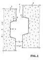
- Fig. 1 shows the gap (1) (longitudinal or transverse gap) of two adjacent tunnel segments (2, 3) made of concrete, which are each provided with a groove (4, 5) (groove depth d, groove width w). Appropriate sealing profiles are now inserted into these grooves. The actual sealing of the gap (1) takes place by compressing the opposite elastomer profiles, the gap distance being reduced from S o to S1. When building tunnels, it must be taken into account that the segments (2, 3) are arranged at an offset X to one another. This tunnel-specific criterion must always be taken into account in leak tests.
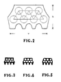
- Fig. 2 shows a sealing profile according to GB-B-2 182 987 with a base width v (breite joint width w) and the height h, the circular channels seen in cross section being offset from one another to form a lattice structure.
- This grid structure is illustrated schematically by the lines from center to center of the channels.
- This structural principle is also the basis of the sealing profiles according to FIGS. 3 to 5, which essentially only have a different shape of the channels.
- FIG. 6 now shows a sealing profile (6) with a two-row arrangement of channels (10, 11, 12, 13, 14, 15), with all channels in each row directly (ie without offset) above the groove grooves (7, 8, 9 ) are arranged, to form webs (lines A, B), which run straight and continuously from the profile base side (16) to the profile back (17). All the webs (A, B) are arranged perpendicular to the profile base side (16) or parallel to the longitudinal center plane Y.
- the channels are essentially semicircular in cross-section, the arcuate part (18, 19) of the channels facing each other.
- the centrally arranged side flanks (20, 20 ') and the side flanks (21, 21') facing the profile back (17) merge into one another with a change in angle.
- the groove grooves (23, 24, 25) and channels (26, 27, 28, 29, 30, 31) with the formation of webs (lines A, B) are also based on the structural principle according to the invention . While the webs (B) arranged in the profile center run perpendicular to the profile base side (32), the outer webs (A) are directed obliquely to the profile center, namely at an angle ⁇ of 10 ⁇ 3 ° (in relation to the longitudinal center plane Y).
- the sealing profile has additional webs (lines C), which are at an angle ⁇ of 45 ⁇ 5 ° (in relation to the longitudinal center plane Y) with simultaneous tangency of the side flank (33, 33 ') and the channels (26, 29, 30; 28 , 30, 31) towards the center of the profile.
- the channels (27, 30) in the profile center are essentially semicircular in shape when viewed in cross section, the arcuate part (36, 37) these channels are arranged to each other.
- the channels located above the outer groove grooves (23, 25) are seen in cross section from asymmetrical (channels 26, 28 of the first row) or of circular shape (channels 29, 31 of the second row).
- the centrally arranged side flanks (33, 33 ') and the side flanks (34, 34') facing the profile back (35) merge into one another with a change in angle.
- Table 2 now summarizes the results of experimental leak tests under tunnel-specific criteria. It should be noted that the sealing profiles according to the invention have a significantly higher sealing performance than the profile types according to FIGS. 2 to 5. This is particularly evident when comparing the sealing profiles according to FIGS. 3 and 7 (Table 3).
- the sealing profile (Fig. 7) in connection with the web system (A, B, C) and a hardness in Shore A of 70 ° is characterized by a particularly high sealing performance of 26 bar.
Landscapes
- Engineering & Computer Science (AREA)
- Structural Engineering (AREA)
- Mining & Mineral Resources (AREA)
- General Life Sciences & Earth Sciences (AREA)
- Civil Engineering (AREA)
- Life Sciences & Earth Sciences (AREA)
- Architecture (AREA)
- Geochemistry & Mineralogy (AREA)
- Geology (AREA)
- Lining And Supports For Tunnels (AREA)
- Sealing Material Composition (AREA)
- Gasket Seals (AREA)
- Road Signs Or Road Markings (AREA)
Abstract
Description
Die Erfindung betrifft ein Dichtungsprofil gemäß Oberbegriff des Anspruchs 1.The invention relates to a sealing profile according to the preamble of
Die Dichtungsrahmen eines Segmentes aus Beton, Stahl, Stahlbeton oder Gußeisen bestehen zumeist aus vier zusammengesetzten strangförmigen Dichtungsprofilen (Profilbänder) aus elastomerem Werkstoff, d.h. aus Gummi oder gummiähnlichem Kunststoff, wobei die Rahmenecken vorzugsweise nach dem Injektion-Molding-Verfahren hergestellt werden. Von besonderer Bedeutung ist der Tunnelbau in Tübbing-Bauweise mit spezieller Anordnung der Segmente. Häufig genügt es, wenn jedes Segment einen Dichtungsrahmen aufweist. Unter besonderen Umständen kann es jedoch erforderlich werden, jedes Segment mit einem Doppeldichtungsrahmen zu versehen, wobei die beiden parallel verlaufenden Dichtungsrahmen mit einem zusätzlichen Dichtungsquerprofil (EP-A-0 337 177) miteinander verbunden sein können. Die Dichtungsprofile bzw. Dichtungsrahmen befinden sich meistens in einer entsprechenden Nut (Nuttiefe d, Nutbreite w) des Tunnel-Segmentes. Unter Einwirkung einer Kraft verringert sich der Spaltabstand zweier Tunnel-Segmente von so (Abstand im unbelasteten Zustand) auf S₁ (Abstand im belasteten Zustand). Dadurch werden die beiden gegenüberliegenden Elastomerprofile zusammengepreßt, was die Abdichtung des Spaltes zur Folge hat.The sealing frames of a segment made of concrete, steel, reinforced concrete or cast iron usually consist of four composite strand-shaped sealing profiles (profiled strips) made of elastomeric material, ie of rubber or rubber-like plastic, the frame corners preferably being produced by the injection molding process. Of particular importance is the tunnel construction in segmental construction with a special arrangement of the segments. It is often sufficient if each segment has a sealing frame. In special circumstances, however, it may be necessary to provide each segment with a double sealing frame, it being possible for the two parallel sealing frames to be connected to one another with an additional sealing cross profile (EP-A-0 337 177). The sealing profiles or sealing frames are usually located in a corresponding groove (groove depth d, groove width w) of the tunnel segment. Under the action of a force, the gap distance between two tunnel segments decreases from s o (distance in the unloaded state) to S₁ (distance in the loaded state). As a result, the two opposite elastomer profiles are pressed together, which results in the sealing of the gap.
Das erste Dichtungsprofil für Tunnel-Segmente wurde 1968 für den Elbtunnel in Hamburg entwickelt, wobei das Elastomerprofil vier Rillennuten aufwies. Bei diesem weltweit ersten Tunnelprojekt, bei dem Dichtungsprofile zum Einsatz kamen, bestanden die Segmente aus Gußeisen (World Tunnelling, 12/1989, Seite 459, Fig. 6). Bei späteren Tunnelprojekten in Kontinentaleuropa, Asien, Nord- und Südamerika sowie in Nordafrika wurden in zunehmenden Maße Segmente aus Beton eingesetzt. Die hierfür entwickelten Dichtungsprofile waren zumeist mit Rillennuten und Kanälen strukturiert (DE-U-78 22 476, DE-C-28 33 345, GB-B-2 178 114, EP-A-0 255 600, EP-A-0 306 796, EP-A-0 368 174, EP-A-0 414 137).The first sealing profile for tunnel segments was developed in 1968 for the Elbe tunnel in Hamburg, whereby the elastomer profile had four groove grooves. In this world's first The tunnel project, in which sealing profiles were used, consisted of cast iron segments (World Tunneling, 12/1989, page 459, Fig. 6). In later tunnel projects in continental Europe, Asia, North and South America and in North Africa, segments of concrete were increasingly used. The sealing profiles developed for this were mostly structured with groove grooves and channels (DE-U-78 22 476, DE-C-28 33 345, GB-B-2 178 114, EP-A-0 255 600, EP-A-0 306 796, EP-A-0 368 174, EP-A-0 414 137).
In Großbritannien dagegen wurde erst 1983 damit begonnen, bei Tunnelprojekten die Segmente mit Elastomerprofilen abzudichten (GB-B-2 170 561; Don Valley Intercepting Sewer, 2/1985, Seite 16). Die besondere geologische Struktur Großbritanniens, insbesondere im Südenglamd durch die Kalksteinbodenformation, erlaubte es, daß über einen langen Zeitraum hinweg bei dem Bau von Tunneln auf eine Abdichtung mit Elastomerprofilen verzichtet werden konnte. Dadurch daß heute die relativ dünnwandigen Britischen Standardsegmente aus Beton lediglich mit einer entsprechenden Nut für die Aufnahme der Elastomerprofile ausgestattet werden und zudem durch die Beibehaltung ihrer alten Struktur unter Bildung von Parallelringen große Spaltweiten im Krümmungsbereich von Tunneln erzeugen, ist in Großbritannien eine Tunnelbausituation gegeben, die sich von der kontinentaleuropäischen Tunnelbauweise, die den Einsatz von konischen Ringen vorsieht, grundlegend unterscheidet (World Tunnelling, 11/1990, Seiten 415 - 420). Aus diesem Grunde wurde 1985 ein Spezialdichtungsprofil entwickelt, das eine zweireihige Anordnung von Kanälen, die unter Bildung einer Gitterstruktur versetzt zueinander angeordnet sind, aufweist (GB-B-2 182 987). Dieser sogenannte 'Doppeldecker' ist heute das Standardprofil in Großbritannien (Tunnelprojekte: Sheffield 3/4, Oldham, Liverpool, London Water Ring Main, Kanaltunnel auf der englischen Seite), das bei geforderter Dichtigkeit gegenüber einem üblichen Wasserdruck von etwa 3 bar (z.B. 3,2 bar bei Projekt Sheffield 4) für unterschiedliche Spaltabstände, insbesondere im Bereich So von 13 bis 20 mm, eingesetzt werden kann.In Great Britain, on the other hand, it was not until 1983 that the segments were sealed with elastomer profiles in tunnel projects (GB-B-2 170 561; Don Valley Intercepting Sewer, 2/1985, page 16). The special geological structure of Great Britain, especially in the south of Glamd due to the limestone floor formation, made it possible to dispense with sealing with elastomer profiles over a long period of time when building tunnels. Due to the fact that the relatively thin-walled British standard segments made of concrete are now only equipped with a corresponding groove for receiving the elastomer profiles and, in addition, by maintaining their old structure with the formation of parallel rings, they produce large gap widths in the curvature area of tunnels, there is a tunnel construction situation in Great Britain differs fundamentally from the continental European tunnel construction, which provides for the use of conical rings (World Tunneling, 11/1990, pages 415 - 420). For this reason, a special sealing profile was developed in 1985, which has a two-row arrangement of channels which are arranged offset from one another to form a lattice structure (GB-B-2 182 987). This so-called 'double-decker' is now the standard profile in Great Britain (tunnel projects: Sheffield 3/4, Oldham, Liverpool, London Water Ring Main, channel tunnel on the English side), which, when required to be watertight, can withstand a normal water pressure of around 3 bar (e.g. 3 , 2 bar in the Sheffield project 4) can be used for different gap distances, in particular in the S o range from 13 to 20 mm.
Immer häufiger entstehen große Tunnel projekte in extrem tiefen Lagen. Zur Zeit befindet sich die Eisenbahnverbindung zwischen Frankreich und England in ihrer Bauphase (ADAC Motorwelt, 1/1991, Seiten 16 - 18), wobei sich die drei Tunnelröhren (2 Verkehrstunnel und 1 Service-Tunnel) an der tiefsten Stelle 100 m unter dem Meeresspiegel befinden. Die geforderte Dichtleistung ist 10 bar (20 bar unter Prüfbedingungen). Ein weiteres Projekt dieser Art wird den Großen Belt unterqueren, wobei hier eine Dichtleistung von 8 bar (16 bar unter Prüfbedingungen) gefordert wird. Dies setzt voraus, daß die Elastomerprofile für die Segmente eine langlebige und absolut sichere Dichtfunktion selbst bei starkem Versatz der Segmente besitzen.Large tunnel projects in extremely deep locations are becoming increasingly common. The rail link between France and England is currently in its construction phase (ADAC Motorwelt, 1/1991, pages 16 - 18), with the three tunnel tubes (2 traffic tunnels and 1 service tunnel) at the deepest point 100 m below sea level are located. The required sealing performance is 10 bar (20 bar under test conditions). Another project of this type will cross under the Great Belt, where a sealing performance of 8 bar (16 bar under test conditions) is required. This presupposes that the elastomer profiles for the segments have a long-lasting and absolutely safe sealing function even when the segments are strongly offset.
Aufgabe der Erfindung ist es daher, Dichtungsprofile zu entwickeln, die höchsten Anforderungen gerecht werden. Gelöst wird diese Aufgabe in überraschender Weise durch eine Profilstruktur gemäß Kennzeichen des Anspruchs 1 (Merkmalsgruppe d).The object of the invention is therefore to develop sealing profiles that meet the highest requirements. This object is surprisingly achieved by a profile structure according to the characterizing part of claim 1 (feature group d).
Die Erfindung wird nun anhand von zwei Ausführungsbeispielen unter Bezugnahme auf schematische Zeichnungen sowie in Verbindung mit Daten aus Dichtheitsprüfungen näher erläutert. Es zeigen:
- Fig. 1
- den abzudichtenden Spalt zweier angrenzender Tunnel-Segmente;
- Fig. 2 bis 5
- Dichtungsprofile mit zweireihiger Anordnung der Kanäle gemäß dem Stand der Technik;
- Fig. 6, 7
- Dichtungsprofile mit der erfindungsgemäßen zweireihigem Anordnung der Kanäle.
- Fig. 1
- the gap to be sealed between two adjacent tunnel segments;
- 2 to 5
- Sealing profiles with a double-row arrangement of the channels according to the prior art;
- 6, 7
- Sealing profiles with the arrangement of the channels in two rows.
Fig. 1 zeigt dem Spalt (1) (Längs- oder Querspalt) zweier angrenzender Tunnel-Segmente (2, 3) aus Beton, die jeweils mit einer Nut (4, 5) (Nuttiefe d, Nutbreite w) versehen sind. In diese Nuten werden nun entsprechende Dichtungsprofile eingesetzt. Die eigentliche Abdichtung des Spaltes (1) erfolgt durch das Zusammenpressen der gegenüberliegenden Elastomerprofile, wobei sich der Spaltabstand von So auf S₁ verringert. Beim Bau von Tunneln muß dabei in Erwägung gezogen werden, daß die Segmente (2, 3) unter einem Versatz X zueinander angeordnet sind. Dieses tunnelspezifische Kriterium muß bei Dichtigkeitsprüfungen stets berücksichtigt werden.Fig. 1 shows the gap (1) (longitudinal or transverse gap) of two adjacent tunnel segments (2, 3) made of concrete, which are each provided with a groove (4, 5) (groove depth d, groove width w). Appropriate sealing profiles are now inserted into these grooves. The actual sealing of the gap (1) takes place by compressing the opposite elastomer profiles, the gap distance being reduced from S o to S₁. When building tunnels, it must be taken into account that the segments (2, 3) are arranged at an offset X to one another. This tunnel-specific criterion must always be taken into account in leak tests.
Fig. 2 zeigt ein Dichtungsprofil gemäß GB-B-2 182 987 mit einer Basisbreite v (≙ Fugenbreite w) und der Höhe h, wobei die im Querschnitt gesehen kreisförmigen Kanäle unter Bildung einer Gitterstruktur versetzt zueinander angeordnet sind. Diese Gitterstruktur wird durch die Linienführung von Mittelpunkt zu Mittelpunkt der Kanäle schematisch verdeutlicht. Dieses Strukturprinzip liegt auch den Dichtungsprofilen gemäß Fig. 3 bis 5 zugrunde, die im wesentlichen lediglich eine andere Form der Kanäle aufweisen.Fig. 2 shows a sealing profile according to GB-B-2 182 987 with a base width v (breite joint width w) and the height h, the circular channels seen in cross section being offset from one another to form a lattice structure. This grid structure is illustrated schematically by the lines from center to center of the channels. This structural principle is also the basis of the sealing profiles according to FIGS. 3 to 5, which essentially only have a different shape of the channels.
Die Tabelle 1 faßt nun hinsichtlich der Dichtungsprofile gemäß Fig. 2 bis 5 die Ergebnisse von experimentellen Dichtheitsprüfungen unter tunnelspezifischen Kriterien zusammen. Dabei liegt die durchschnittliche Dichtleistung bei 4 bar, die bei vielen Tunnelprojekten, insbesondere in Großbritannien, den Dichtheitsanforderungen genügt. Dabei haben die unterschiedlichen Formen und Größen der Kanäle keinen wesentlichen Einfluß auf die Dichtleistung. Benford's Aussage (Construction Today, 5/1990, Seite 15), daß verschiedene Konfigurationen und Größen der Kanäle bei gleicher Grundstruktur (d.h. Gitterstruktur) einen wesentlichen Einfluß auf die Höhe der Dichtleistung haben, wird hiermit widerlegt. Wie die Untersuchung zu dem Dichtprofil gemäß Fig. 3 zeigt, kann die Dichtleistung jedoch verbessert werden, wenn die Härte in Shore A von 65° auf 70° erhöht wird. Der Erhöhung der Shore-Härte zwecks Verbesserung der Dichtleistung sind jedoch Grenzen gesetzt, da es sonst zu Ausbrüchen an den Betonsegmenten kommen kann.With regard to the sealing profiles according to FIGS. 2 to 5, Table 1 now summarizes the results of experimental leak tests under tunnel-specific criteria. The average sealing performance is 4 bar, which in many tunnel projects, especially in Great Britain, meets the tightness requirements. The different shapes and sizes of the channels have no significant influence on the sealing performance. Benford's statement (Construction Today, 5/1990, page 15) that different configurations and sizes of the channels with the same basic structure (ie lattice structure) have a significant influence on the level of sealing performance is hereby refuted. As the 3 shows, however, the sealing performance can be improved if the hardness in Shore A is increased from 65 ° to 70 °. However, there are limits to increasing the Shore hardness in order to improve the sealing performance, otherwise there may be chipping on the concrete segments.
Fig. 6 zeigt nun ein Dichtungsprofil (6) mit zweireihiger Anordnung von Kanälen (10, 11, 12, 13, 14, 15), wobei in jeder Reihe sämtliche Kanäle direkt (d.h. ohne Versatz) über den Rillennuten (7, 8, 9) angeordnet sind, und zwar unter Bildung vom Stegen (Linienführung A, B), die vom der Profilbasisseite (16) aus zum Profilrücken (17) hin geradlinig und durchgehend verlaufen. Sämtliche Stege (A, B) sind dabei senkrecht zur Profilbasisseite (16) bzw. parallel zur Längsmittelebene Y angeordnet. Die Kanäle sind im Querschnitt gesehen im wesentlichen von halbkreisförmiger Gestalt, wobei der bogenförmige Teil (18, 19) der Kanäle aufeinander zugerichtet ist. Die mittig angeordneten Seitenflanken (20, 20') und die dem Profilrücken (17) zugewandten Seitenflanken (21, 21') gehen unter Winkeländerung ineinander über.6 now shows a sealing profile (6) with a two-row arrangement of channels (10, 11, 12, 13, 14, 15), with all channels in each row directly (ie without offset) above the groove grooves (7, 8, 9 ) are arranged, to form webs (lines A, B), which run straight and continuously from the profile base side (16) to the profile back (17). All the webs (A, B) are arranged perpendicular to the profile base side (16) or parallel to the longitudinal center plane Y. The channels are essentially semicircular in cross-section, the arcuate part (18, 19) of the channels facing each other. The centrally arranged side flanks (20, 20 ') and the side flanks (21, 21') facing the profile back (17) merge into one another with a change in angle.
Bei dem Dichtungsprofil (22) gemäß Fig. 7 liegt den Rillennuten (23, 24, 25) und Kanälen (26, 27, 28, 29, 30, 31) unter Bildung von Stegen (Linienführung A, B) ebenfalls das erfindungsgemäße Strukturprinzip zugrunde. Während die im Profilzentrum angeordneten Stege (B) senkrecht zur Profilbasisseite (32) verlaufen, sind die Außenstege (A) schräg zur Profilmitte gerichtet, und zwar im einem Winkel α von 10 ± 3° (bezogen auf Längsmittelebene Y). Ferner weist das Dichtungsprofil zusätzliche Stege (Linienführung C) auf, die in einem Winkel β von 45 ± 5° (bezogen auf Längsmittelebene Y) unter gleichzeitiger Tangierung der Seitenflanke (33, 33') und der Kanäle (26, 29, 30; 28, 30, 31) auf die Profilmitte zuverlaufen. Die Kanäle (27, 30) im Profilzentrum sind im Querschnitt gesehen im wesentlichen vom halbkreisförmiger Gestalt, wobei der bogenförmige Teil (36, 37) dieser Kanäle zueinander angeordnet ist. Die über den äußeren Rillennuten (23, 25) sich befindenden Kanälen sind im Querschnitt gesehen vom asymmetrischer (Kanäle 26, 28 der ersten Reihe) bzw. von kreisförmiger Gestalt (Kanäle 29, 31 der zweiten Reihe). Die mittig angeordneten Seitenflanken (33, 33') und die zum Profilrücken (35) zugewandten Seitenflanken (34, 34') gehen unter Winkeländerung ineinander über.7, the groove grooves (23, 24, 25) and channels (26, 27, 28, 29, 30, 31) with the formation of webs (lines A, B) are also based on the structural principle according to the invention . While the webs (B) arranged in the profile center run perpendicular to the profile base side (32), the outer webs (A) are directed obliquely to the profile center, namely at an angle α of 10 ± 3 ° (in relation to the longitudinal center plane Y). Furthermore, the sealing profile has additional webs (lines C), which are at an angle β of 45 ± 5 ° (in relation to the longitudinal center plane Y) with simultaneous tangency of the side flank (33, 33 ') and the channels (26, 29, 30; 28 , 30, 31) towards the center of the profile. The channels (27, 30) in the profile center are essentially semicircular in shape when viewed in cross section, the arcuate part (36, 37) these channels are arranged to each other. The channels located above the outer groove grooves (23, 25) are seen in cross section from asymmetrical (
Die Tabelle 2 faßt nun hinsichtlich der Dichtungsprofile gemäß Fig. 6 und 7 die Ergebnisse von expermimentellen Dichtheitsprüfungen unter tunnelspezifischen Kriterien zusammen. Dabei ist festzuhalten, daß die erfindungsgemäßen Dichtungsprofile eine wesentlich höhere Dichtleistung haben als die Profiltypen gemäß Fig. 2 bis 5. Dies wird besonders ersichtlich bei einem Vergleich der Dichtungsprofile gemäß Fig. 3 und 7 (Tabelle 3). Dabei zeichnet sich das Dichtungsprofil (Fig. 7) in Verbindung mit dem Stegensystem (A, B, C) und einer Härte in Shore A von 70° durch eine besonders hohe Dichtleistung von 26 bar aus.With regard to the sealing profiles according to FIGS. 6 and 7, Table 2 now summarizes the results of experimental leak tests under tunnel-specific criteria. It should be noted that the sealing profiles according to the invention have a significantly higher sealing performance than the profile types according to FIGS. 2 to 5. This is particularly evident when comparing the sealing profiles according to FIGS. 3 and 7 (Table 3). The sealing profile (Fig. 7) in connection with the web system (A, B, C) and a hardness in Shore A of 70 ° is characterized by a particularly high sealing performance of 26 bar.
Auch wenn die beiden Ausführungsbeispiele (Fig. 6, 7) ausschließlich auf Dichtungsprofile mit offenen Rillennuten eingehen, so ist das erfindungsgemäße Strukturprinzip der zweireihigen Anordnung der Kanäle auch auf Profile mit ganz oder teilweise geschlossenen Rillennuten (GB-A-2 017 194) anwendbar.


Claims (13)
dadurch gekennzeichnet, daß
characterized in that
Applications Claiming Priority (4)
| Application Number | Priority Date | Filing Date | Title |
|---|---|---|---|
| DE4003583 | 1990-02-07 | ||
| DE4003583 | 1990-02-07 | ||
| DE4004347 | 1990-02-13 | ||
| DE4004347 | 1990-02-13 |
Publications (2)
| Publication Number | Publication Date |
|---|---|
| EP0441250A1 true EP0441250A1 (en) | 1991-08-14 |
| EP0441250B1 EP0441250B1 (en) | 1994-04-20 |
Family
ID=25889832
Family Applications (1)
| Application Number | Title | Priority Date | Filing Date |
|---|---|---|---|
| EP91101335A Expired - Lifetime EP0441250B1 (en) | 1990-02-07 | 1991-02-01 | Sealing strip for tunnel segments |
Country Status (5)
| Country | Link |
|---|---|
| EP (1) | EP0441250B1 (en) |
| AT (1) | ATE104743T1 (en) |
| DE (2) | DE59101409D1 (en) |
| DK (1) | DK0441250T3 (en) |
| ES (1) | ES2056503T3 (en) |
Cited By (7)
| Publication number | Priority date | Publication date | Assignee | Title |
|---|---|---|---|---|
| EP0534277A1 (en) | 1991-09-21 | 1993-03-31 | Phoenix Aktiengesellschaft | Sealing strip for tunnel lining segments |
| WO1994016197A1 (en) * | 1993-01-14 | 1994-07-21 | Phoenix Aktiengesellschaft | Sealing profile for tubular tunnel segments, in particular for elements floated into position |
| WO1999002820A1 (en) * | 1997-07-08 | 1999-01-21 | Phoenix Aktiengesellschaft | Sealing arrangement for tunnel segments |
| WO1999054593A1 (en) | 1998-04-20 | 1999-10-28 | Hochtief Aktiengesellschaft Vorm. Gebr. Helfmann | Device and method for fixing a sealing element on a casing in a stable position |
| DE102009015232A1 (en) | 2009-04-01 | 2010-10-07 | Phoenix Dichtungstechnik Gmbh | Sealing arrangement for shaft and tunnel constructions |
| WO2011063804A2 (en) | 2009-11-30 | 2011-06-03 | Phoenix Dichtungstechnik Gmbh | Sealing arrangement for shaft and tunnel constructions |
| CN106050275A (en) * | 2016-07-13 | 2016-10-26 | 同济大学 | Sealing waterproof device for bolt hole of shield tunnel duct pieces |
Families Citing this family (3)
| Publication number | Priority date | Publication date | Assignee | Title |
|---|---|---|---|---|
| ES2254581T3 (en) | 2001-10-11 | 2006-06-16 | Datwyler Ag Schweizerische Kabel-, Gummi- Und Kunststoffwerke | SHUTTER PROFILE FOR TUNNEL SEGMENTS. |
| WO2005088075A1 (en) * | 2004-03-11 | 2005-09-22 | Phoenix Ag | Seal arrangement |
| DE102016121452B4 (en) * | 2016-11-09 | 2019-09-19 | CTS Cordes tubes & seals GmbH & Co. KG | Sealing profile, and thus equipped seal assembly |
Citations (3)
| Publication number | Priority date | Publication date | Assignee | Title |
|---|---|---|---|---|
| EP0222968A1 (en) * | 1985-11-15 | 1987-05-27 | Phoenix Aktiengesellschaft | Sealing profile for tunnel tubes |
| EP0306796A1 (en) * | 1987-09-05 | 1989-03-15 | Phoenix Aktiengesellschaft | Sealing profile for tunnel segments |
| GB2210117A (en) * | 1987-12-15 | 1989-06-01 | Phoenix Ag | Sealing profile for tunnel segments |
-
1991
- 1991-02-01 EP EP91101335A patent/EP0441250B1/en not_active Expired - Lifetime
- 1991-02-01 ES ES91101335T patent/ES2056503T3/en not_active Expired - Lifetime
- 1991-02-01 DE DE59101409T patent/DE59101409D1/en not_active Expired - Lifetime
- 1991-02-01 DK DK91101335.7T patent/DK0441250T3/en active
- 1991-02-01 DE DE4103089A patent/DE4103089A1/en not_active Withdrawn
- 1991-02-01 AT AT9191101335T patent/ATE104743T1/en not_active IP Right Cessation
Patent Citations (3)
| Publication number | Priority date | Publication date | Assignee | Title |
|---|---|---|---|---|
| EP0222968A1 (en) * | 1985-11-15 | 1987-05-27 | Phoenix Aktiengesellschaft | Sealing profile for tunnel tubes |
| EP0306796A1 (en) * | 1987-09-05 | 1989-03-15 | Phoenix Aktiengesellschaft | Sealing profile for tunnel segments |
| GB2210117A (en) * | 1987-12-15 | 1989-06-01 | Phoenix Ag | Sealing profile for tunnel segments |
Cited By (13)
| Publication number | Priority date | Publication date | Assignee | Title |
|---|---|---|---|---|
| EP0534277A1 (en) | 1991-09-21 | 1993-03-31 | Phoenix Aktiengesellschaft | Sealing strip for tunnel lining segments |
| WO1994016197A1 (en) * | 1993-01-14 | 1994-07-21 | Phoenix Aktiengesellschaft | Sealing profile for tubular tunnel segments, in particular for elements floated into position |
| US6238139B1 (en) | 1993-01-14 | 2001-05-29 | Phoenix Aktiengesellschaft | Sealing arrangement |
| WO1999002820A1 (en) * | 1997-07-08 | 1999-01-21 | Phoenix Aktiengesellschaft | Sealing arrangement for tunnel segments |
| US6267536B1 (en) | 1997-07-08 | 2001-07-31 | Phoenix Aktiengesellschaft | Sealing arrangement for tunnel segments |
| WO1999054593A1 (en) | 1998-04-20 | 1999-10-28 | Hochtief Aktiengesellschaft Vorm. Gebr. Helfmann | Device and method for fixing a sealing element on a casing in a stable position |
| DE102009015232A1 (en) | 2009-04-01 | 2010-10-07 | Phoenix Dichtungstechnik Gmbh | Sealing arrangement for shaft and tunnel constructions |
| WO2010112015A3 (en) * | 2009-04-01 | 2011-03-03 | Phoenix Dichtungstechnik Gmbh | Sealing arrangement for shaft and tunnel construction |
| WO2011063804A2 (en) | 2009-11-30 | 2011-06-03 | Phoenix Dichtungstechnik Gmbh | Sealing arrangement for shaft and tunnel constructions |
| DE102009056063A1 (en) | 2009-11-30 | 2011-07-14 | Phoenix Dichtungstechnik GmbH, 99880 | Sealing arrangement for shaft and tunnel constructions |
| US9222358B2 (en) | 2009-11-30 | 2015-12-29 | Daetwyler Sealing Technologies Deutschland Gmbh | Sealing arrangement for shaft and tunnel constructions |
| CN106050275A (en) * | 2016-07-13 | 2016-10-26 | 同济大学 | Sealing waterproof device for bolt hole of shield tunnel duct pieces |
| CN106050275B (en) * | 2016-07-13 | 2018-10-26 | 同济大学 | A kind of duct pieces of shield tunnel bolt hole sealed waterproof device |
Also Published As
| Publication number | Publication date |
|---|---|
| ES2056503T3 (en) | 1994-10-01 |
| DE4103089A1 (en) | 1991-08-08 |
| ATE104743T1 (en) | 1994-05-15 |
| EP0441250B1 (en) | 1994-04-20 |
| DK0441250T3 (en) | 1994-07-25 |
| DE59101409D1 (en) | 1994-05-26 |
Similar Documents
| Publication | Publication Date | Title |
|---|---|---|
| EP0306796B1 (en) | Sealing profile for tunnel segments | |
| EP0807204B1 (en) | Seal arrangement for tubular tunnel segments | |
| EP0521324B2 (en) | Cable sleeve | |
| EP0441250B1 (en) | Sealing strip for tunnel segments | |
| EP0255600A1 (en) | Sealing profile for segments of tunnel tubes | |
| EP0995013B1 (en) | Sealing arrangement for tunnel segments | |
| EP1095206B1 (en) | Sealing device | |
| EP0414137B1 (en) | Sealing profile for tunnel-segments | |
| EP1302626B1 (en) | Sealing section for tunnel segments | |
| EP0863334B1 (en) | Bellow | |
| EP0629262B1 (en) | Sealing profile for tubular tunnel segments, in particular for elements floated into position | |
| EP0368174B1 (en) | Sealing strip for tunnel segments | |
| CH677262A5 (en) | ||
| EP0337177B1 (en) | Seal for tunnel segments | |
| CH686383A5 (en) | Process for preventing profile sealing strip moving relatively to tunnel structural element | |
| DE3020710C2 (en) | ||
| DE9317172U1 (en) | Sealing, decorative or end strip | |
| EP1723309B1 (en) | Seal arrangement | |
| DE19616143C1 (en) | Annular lining for tunnels, using rings with tongue and groove joints | |
| EP0534277B1 (en) | Sealing strip for tunnel lining segments | |
| DE3829286A1 (en) | Sealing profile for tunnel segments | |
| DE2224230C3 (en) | Precast concrete containers | |
| DE2235158C3 (en) | Joint sealing strip made of rubber-elastic material | |
| DE3121986A1 (en) | Sealing arrangement for a spigot-and-socket joint on pipes | |
| DE3840441A1 (en) | Sealing profile for tunnel segments |
Legal Events
| Date | Code | Title | Description |
|---|---|---|---|
| PUAI | Public reference made under article 153(3) epc to a published international application that has entered the european phase |
Free format text: ORIGINAL CODE: 0009012 |
|
| AK | Designated contracting states |
Kind code of ref document: A1 Designated state(s): AT BE CH DE DK ES FR GB GR IT LI LU NL SE |
|
| 17P | Request for examination filed |
Effective date: 19910829 |
|
| GBC | Gb: translation of claims filed (gb section 78(7)/1977) | ||
| 17Q | First examination report despatched |
Effective date: 19920804 |
|
| GRAA | (expected) grant |
Free format text: ORIGINAL CODE: 0009210 |
|
| AK | Designated contracting states |
Kind code of ref document: B1 Designated state(s): AT BE CH DE DK ES FR GB GR IT LI LU NL SE |
|
| REF | Corresponds to: |
Ref document number: 104743 Country of ref document: AT Date of ref document: 19940515 Kind code of ref document: T |
|
| ITF | It: translation for a ep patent filed | ||
| REF | Corresponds to: |
Ref document number: 59101409 Country of ref document: DE Date of ref document: 19940526 |
|
| GBT | Gb: translation of ep patent filed (gb section 77(6)(a)/1977) |
Effective date: 19940621 |
|
| REG | Reference to a national code |
Ref country code: DK Ref legal event code: T3 |
|
| ET | Fr: translation filed | ||
| REG | Reference to a national code |
Ref country code: GR Ref legal event code: FG4A Free format text: 3012474 |
|
| REG | Reference to a national code |
Ref country code: ES Ref legal event code: FG2A Ref document number: 2056503 Country of ref document: ES Kind code of ref document: T3 |
|
| EAL | Se: european patent in force in sweden |
Ref document number: 91101335.7 |
|
| PLBE | No opposition filed within time limit |
Free format text: ORIGINAL CODE: 0009261 |
|
| STAA | Information on the status of an ep patent application or granted ep patent |
Free format text: STATUS: NO OPPOSITION FILED WITHIN TIME LIMIT |
|
| 26N | No opposition filed | ||
| REG | Reference to a national code |
Ref country code: GB Ref legal event code: IF02 |
|
| PGFP | Annual fee paid to national office [announced via postgrant information from national office to epo] |
Ref country code: GR Payment date: 20041221 Year of fee payment: 15 |
|
| PGFP | Annual fee paid to national office [announced via postgrant information from national office to epo] |
Ref country code: LU Payment date: 20050112 Year of fee payment: 15 |
|
| PGFP | Annual fee paid to national office [announced via postgrant information from national office to epo] |
Ref country code: DK Payment date: 20050201 Year of fee payment: 15 |
|
| PG25 | Lapsed in a contracting state [announced via postgrant information from national office to epo] |
Ref country code: DK Free format text: LAPSE BECAUSE OF NON-PAYMENT OF DUE FEES Effective date: 20060228 Ref country code: LU Free format text: LAPSE BECAUSE OF NON-PAYMENT OF DUE FEES Effective date: 20060228 |
|
| REG | Reference to a national code |
Ref country code: DK Ref legal event code: EBP |
|
| REG | Reference to a national code |
Ref country code: CH Ref legal event code: PFA Owner name: PHOENIX AKTIENGESELLSCHAFT Free format text: PHOENIX AKTIENGESELLSCHAFT#HANNOVERSCHE STRASSE 88#D-21079 HAMBURG (DE) -TRANSFER TO- PHOENIX AKTIENGESELLSCHAFT#HANNOVERSCHE STRASSE 88#D-21079 HAMBURG (DE) |
|
| PG25 | Lapsed in a contracting state [announced via postgrant information from national office to epo] |
Ref country code: GR Free format text: LAPSE BECAUSE OF NON-PAYMENT OF DUE FEES Effective date: 20060904 |
|
| PGFP | Annual fee paid to national office [announced via postgrant information from national office to epo] |
Ref country code: DE Payment date: 20100228 Year of fee payment: 20 |
|
| PGFP | Annual fee paid to national office [announced via postgrant information from national office to epo] |
Ref country code: ES Payment date: 20100726 Year of fee payment: 20 Ref country code: CH Payment date: 20100726 Year of fee payment: 20 Ref country code: NL Payment date: 20100723 Year of fee payment: 20 |
|
| PGFP | Annual fee paid to national office [announced via postgrant information from national office to epo] |
Ref country code: FR Payment date: 20100805 Year of fee payment: 20 Ref country code: SE Payment date: 20100723 Year of fee payment: 20 Ref country code: IT Payment date: 20100726 Year of fee payment: 20 Ref country code: AT Payment date: 20100723 Year of fee payment: 20 |
|
| PGFP | Annual fee paid to national office [announced via postgrant information from national office to epo] |
Ref country code: GB Payment date: 20100722 Year of fee payment: 20 |
|
| REG | Reference to a national code |
Ref country code: DE Ref legal event code: R071 Ref document number: 59101409 Country of ref document: DE |
|
| REG | Reference to a national code |
Ref country code: NL Ref legal event code: V4 Effective date: 20110201 |
|
| REG | Reference to a national code |
Ref country code: CH Ref legal event code: PL |
|
| REG | Reference to a national code |
Ref country code: GB Ref legal event code: PE20 Expiry date: 20110131 |
|
| BE20 | Be: patent expired |
Owner name: *PHOENIX A.G. Effective date: 20110201 |
|
| PGFP | Annual fee paid to national office [announced via postgrant information from national office to epo] |
Ref country code: BE Payment date: 20100729 Year of fee payment: 20 |
|
| REG | Reference to a national code |
Ref country code: ES Ref legal event code: FD2A Effective date: 20110222 |
|
| EUG | Se: european patent has lapsed | ||
| PG25 | Lapsed in a contracting state [announced via postgrant information from national office to epo] |
Ref country code: NL Free format text: LAPSE BECAUSE OF EXPIRATION OF PROTECTION Effective date: 20110201 |
|
| PG25 | Lapsed in a contracting state [announced via postgrant information from national office to epo] |
Ref country code: GB Free format text: LAPSE BECAUSE OF EXPIRATION OF PROTECTION Effective date: 20110131 Ref country code: ES Free format text: LAPSE BECAUSE OF EXPIRATION OF PROTECTION Effective date: 20110202 |
|
| PG25 | Lapsed in a contracting state [announced via postgrant information from national office to epo] |
Ref country code: DE Free format text: LAPSE BECAUSE OF EXPIRATION OF PROTECTION Effective date: 20110201 |