EP0441342B1 - Dispositif de réduction de bruit pour l'élimination de bruit périodique - Google Patents
Dispositif de réduction de bruit pour l'élimination de bruit périodique Download PDFInfo
- Publication number
- EP0441342B1 EP0441342B1 EP91101606A EP91101606A EP0441342B1 EP 0441342 B1 EP0441342 B1 EP 0441342B1 EP 91101606 A EP91101606 A EP 91101606A EP 91101606 A EP91101606 A EP 91101606A EP 0441342 B1 EP0441342 B1 EP 0441342B1
- Authority
- EP
- European Patent Office
- Prior art keywords
- signal
- noise
- output
- signal output
- periodic noise
- Prior art date
- Legal status (The legal status is an assumption and is not a legal conclusion. Google has not performed a legal analysis and makes no representation as to the accuracy of the status listed.)
- Expired - Lifetime
Links
Images


Classifications
-
- H—ELECTRICITY
- H04—ELECTRIC COMMUNICATION TECHNIQUE
- H04N—PICTORIAL COMMUNICATION, e.g. TELEVISION
- H04N5/00—Details of television systems
- H04N5/76—Television signal recording
- H04N5/91—Television signal processing therefor
- H04N5/93—Regeneration of the television signal or of selected parts thereof
-
- H—ELECTRICITY
- H04—ELECTRIC COMMUNICATION TECHNIQUE
- H04N—PICTORIAL COMMUNICATION, e.g. TELEVISION
- H04N5/00—Details of television systems
- H04N5/76—Television signal recording
- H04N5/91—Television signal processing therefor
- H04N5/911—Television signal processing therefor for the suppression of noise
Definitions
- This invention relates to a noise reduction apparatus for eliminating periodic noise in videotape recorders or the like.
- VTR devices videotape recorder devices
- the rotary head and related components can develop periodic noises.
- These periodic noises include fluctuations in the chrominance signal phase or changes in the luminance signal level.
- Such periodic noises can cause a particular portion of the screen to vary in color or brightness over a specific range. These phenomena have not been generally considered a result of noises, but, in most cases, of signal themselves.
- the VTR device is provided with various noise reduction devices for noise removal.
- those noise reduction devices are for removing random noises rather than periodic noises.
- DE-A-3 400 103 A1 discloses a method and device for removing noise from a signal, especially an audio signal.
- a noise portion of the signal is detected and used as a reference noise signal in a memory section, and the stored digitalized signal is used for compensating a noise component under computer control.
- the device and method disclosed in this document are directed towards removing a noise on a specific recording. According to this document, a disturbance signal is split into a hum signal and a noise signal.
- JP-A-60016028 discloses a noise separating method for a continuous frequency signal in which noise from an AC power supply wave is separated at first by a filter, after which the extracted noise waveform is converted into a digital signal of which an average is taken and this average value is stored in a memory. Then, a continuous frequency signal is received and an average value thereof is calculated. A circuit subtracts the average noise waveform from the average reception waveform so as to extract a signal waveform.
- US-A-4 807 034 discloses a noise reduction circuit for a video signal having a field memory.
- a noise reduction circuit allows a field memory to store one field data of a video signal through a subtracting circuit.
- a noise reduction circuit causes a subtracting circuit to subtract a delayed video signal having a 1-field time delay.
- a noise component included in the video signal is extracted by a noise extracting circuit in accordance with a field difference signal and is output to the subtracting circuit.
- the noise component is compared with a predetermined reference value so as to determine whether the video signal represents a motion or motionless picture.
- the object of the present invention is to provide a noise reduction apparatus that ensures a removal of periodic noises.
- the object is accomplished by a noise reduction apparatus having the features described in claim 1 and by a method described in claim 11.
- the periodic noise output from the signal processing means is extracted by the extracting means to store it in the memory means.
- the electric signal output by the converting means and supplied from the second videotape is processed by the signal processing means.
- the periodic noise stored in the memory means is subtracted from the signal output from the signal processing means. As a result of this, the periodic noise is positively removed from the video signal reproduced from the second videotape.
- Fig. 1 illustrates the application of the present invention to a VTR device.
- a video signal, as magnetic information, recorded on to a videotape VT1 is converted by a rotary head 10 into an electric signal, which is then supplied to a VTR signal processing section 11.
- the VTR signal processing section 11 whose construction is known, reproduces a video signal from the frequency-modulated luminance and chrominance signals supplied from the rotary head 10.
- the video signal output by the VTR signal processing section 11 is supplied to a noise extracting section 12.
- Fig. 2 shows a first embodiment of the noise extracting section 12, which is composed of, for example, a filter 12A and an A/D converter 12B.
- the filter 12A is set according to the frequency band of the noise to be removed and may be made up of a low-pass filter or a high-pass filter.
- the noise extracting section 12 extracts the periodic noise with a period of one frame or field, via the filter 12A, from the signal reproduced by the VTR signal processing section 11, and the extracted signal is converted into a digital signal by the A/D converter 12B.
- the noise extracted by the noise extracting section 12 is supplied to the memory section 13.
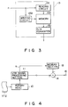
- Fig. 3 shows the arrangement of the memory section 13, which is composed of, for example, a memory 13A made up of a DRAM (Dynamic Random Access Memory), a writing circuit 13B, a reading circuit 13C, and a D/A converter 13D.
- the memory 13A has, for example, one field of memory capacity.
- the writing circuit 13B writes the extracted noise into the memory 13A in synchronism with the reproduction timing of the VTR signal processing section 11 such as the rotational period of the rotary drum, or with the timing signal n for one field.
- the reading circuit 13C reads the stored signal from the memory 13A in synchronization with the timing signal n.
- the D/A converter 13D converts the noise signal read from the memory 13A into an analog signal.
- Both the noise signal from the D/A converter 13D and the video signal from the VTR signal processing section 11 are supplied to a subtracting circuit 14.
- the subtracting circuit 14 eliminates periodic noise from the video signal by, during VTR reproduction, subtracting the noise signal output by the D/A converter 13D, from the VTR signal processing section 11.
- the resulting noise-free video signal is output from the output terminal 15.
- the noise extracting section 12 it is not necessary for the noise extracting section 12 to extract noise constantly. For example, it may be done in inspection work during the manufacture of VTR devices. In this case, the noise extracting section 12 is connected between the output of the VTR signal processing section 11 and the memory section 13 to store the noise extracted by the noise extracting section 12, into the memory 13A. After the storing of the noise into the memory 13A, the noise extracting section 12 is disconnected from between the output of the VTR signal processing section 11 and the memory section 13.
- a videotape to which no video signal is recorded is used as the videotape VT1.
- the reproduction of the no-signal videotape by the rotary head 10 and VTR signal processing section 11 results in the reproduced signal containing periodic noise. That is, the reproduced signal includes white noise and periodic noise.
- the filter 12A in the noise extracting section 12 extracts periodic noise from the reproduced signal over, for example, one field.
- the extracted noise is converted by the A/D converter 12B into a digital signal, which is then stored into the memory 13A in response to the timing signal n.
- the memory 13A only the extracted periodic noise is stored at regular intervals in response to the timing signal n.
- Fig. 4 shows the way that a videotape VT2, to which a desired video signal is recorded, is reproduced by a VTR device, whose memory 13A has stored periodic noise as mentioned above.
- the noise extracting section 12 has been disconnected.
- the signal output by the VTR signal processing section 11 also contains periodic noise as in the case of reproducing no-signal videotape.
- periodic noise can be removed by reproducing a video signal with the VTR signal processing section 11 and at the same time, reading the noise from the memory section 13 in synchronism with the timing signal n output from the VTR signal processing section 11, and then extracting the noise read from the memory section 13 from the video signal output by the VTR signal processing section 11.
- the periodic noise is extracted by the noise extracting section 12 and stored into the memory section 13.
- the stored noise in the memory section 13 is read out in synchronization with the VTR signal output by signal processing section 11, and is extracted from the reproduced signal. This assures elimination of the periodic noise.
- the embodiment allows removal of periodic noises irrespective of the cause of noises, providing a lot of flexibility in applications.
- the amount to be extracted is not limited to one field and may be one frame, depending on the period of noise.
- VTR signal processing section 11 converts the reproduced signal into a digital signal, this will make it unnecessary to use the A/D converter 12B in the noise extracting section 12 and the D/A converter 13D that converts the noise read from the memory 13A into an analog signal.
- the noise extracting section 12 is connected to the output of the VTR signal processing section 11 to extract periodic noise from a video signal
- the noise may be extracted from the frequency-modulated signal output from the rotary head 10 to remove the noise at the stage where the signal is frequency-modulated.
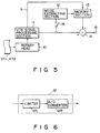
- the VTR device does not have the noise extracting section 12, which is connected to it only when noise is extracted, it may contain the noise extracting section 12.
- the noise extracting section 12 is connected via the switch 16 to the output of the VTR signal processing section 11.
- the switch 16 may be changed manually or automatically at, for example, regular intervals in the VTR device.
- Fig. 6 illustrates a second embodiment of the noise extracting section 12.
- the output of the VTR signal processing section 11 (not shown) is connected to the input of the limiter 12C, the output of which is connected to the A/D converter 12B.
- the limiter 12C is capable of changing the limit level. The adjustment of the level allows only the desired noise to be extracted.
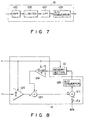
- Fig. 7 shows a third embodiment of the noise extracting section 12 which is a combination of a filter and a limiter.
- the output of the VTR signal processing section 11 (not shown) is connected to the input of the high-pass filter (HPF) 12D, the output of which is connected to the input of the limiter 12E.
- the output of the limiter 12E is connected to the input of the low-pass filter (LPF) 12F, the output of which is connected to the A/D converter 12B.
- HPF high-pass filter
- LPF low-pass filter
- Fig. 8 illustrates a fourth embodiment of the noise extracting section 12.
- the output of the VTR signal processing section 11 (not shown) is connected to the input of the amplifier 12G, the output of which is connected to one input of the adder 12H.
- the output of the adder 12H is connected to one input of the adder 12I, the other input of which is connected to the switch 12J, via which the average of white noise WN can be supplied.
- the output of the adder 12I is connected via the A/D converter 12B to the input of the memory section 13, the output of which is connected to the input of the amplifier 12K, the output of which is connected to the other input of the adder 12H.
- Each of these amplifiers 12G and 12K is composed of a variable gain control amplifier. If the output level of a video signal is A (a constant) and the timing signal corresponding to the field number (the number of rotations of the rotary drum) of the video signal is n, the gain G1 of the amplifier 12G will be controlled to A/n and the gain G2 of the amplifier 12K is controlled to (n-1)A/n.
- the video signal output from the amplifier 12G is supplied to the adders 12H and 12I in sequence, while any signal is not output from the amplifier 12K and the average value of white noise is not supplied via the switch 12. This causes the level-A video signal to be stored in the memory section 13 via the A/D converter 12B.
- the level-A video signal output from the VTR signal processing section 11 is amplified to A/2 by the amplifier 12G and supplied to the adder 12H, to which the amplifier 12K-output video signal is also supplied.
- the video signal is obtained by reading it from the memory section 13 and amplifying it with the amplifier 12K. That is, the level A video signal read from the memory section 13 is amplified by the amplifier 12K to form the level A/2 video signal.
- Each level A/2 video signal from the amplifiers 12G and 12K is added at the adder 12H to produce the level-A video signal, which is in turn stored, via the adder 12I and the A/D converter 12B, in the memory section 13.
- the output level is constant.
- the periodic noise and the average value of white noise will be stored in the memory section 13.
- the switch 12J when the switch 12J is turned on, the white-noise average value WN input via the switch 12J is subtracted from the periodic noise and the white-noise average value read from the memory section 13, at the adder 12I. This allows extraction of the periodic noise only.
- the extracted periodic noise is stored via the A/D converter 12B into the memory section 13.
- this embodiment allows more reliable extraction of periodic noises.
- Fig. 10 illustrates a fifth embodiment of the noise extracting section 12. While in the embodiments described so far, a no-signal videotape is used to extract periodic noises, it may be possible to use a videotape containing a reference signal distinguishable from noise.
- Fig. 10 showing an embodiment that extracts periodic noises by using a reference signal-recorded videotape
- the same parts as in Fig. 8 are indicated by the same symbols.
- one input of the adder 12L is connected to the output of the VTR signal processing section 11 (not shown).
- the other input of the adder 12L is supplied with the same reference signal S as recorded on the videotape.
- the output of the adder 12H is connected to the memory section 13.
- the video signal containing the reference signal and periodic noise output from the VTR signal processing section 11 is supplied to the adder 12L, which subtracts the reference signal from the video signal.
- This reference signal-subtracted video signal is stored in the memory section 13 in the similar manner as described above. As a result, periodic noise is recorded in the memory section 13.
- the present invention is not limited to VTR apparatus and may be applied to devices that produces periodic noises.
Landscapes
- Engineering & Computer Science (AREA)
- Multimedia (AREA)
- Signal Processing (AREA)
- Television Signal Processing For Recording (AREA)
- Picture Signal Circuits (AREA)
- Signal Processing Not Specific To The Method Of Recording And Reproducing (AREA)
- Noise Elimination (AREA)
Claims (11)
- Un dispositif de réduction de bruit pour éliminer du bruit périodique dans un dispositif destiné à reproduire des enregistrements qui produit du bruit périodique, comprenantdes moyens d'extraction (12) pour extraire du bruit périodique d'un signal contenant du bruit périodique qui est reproduit à partir d'un enregistrement et qui est émis par des moyens d'émission de signal (11); etdes moyens d'enregistrement (13) pour enregistrer le bruit périodique extrait;caractérisé en ce queles moyens d'extraction (12) sont conçus de façon à extraire seulement du bruit périodique lorsqu'un premier enregistrement spécifique est reproduit, à titre de référence, de façon que les moyens d'enregistrement (13) enregistrent le bruit périodique qui est extrait du signal correspondant au premier enregistrement spécifique; etdes moyens de soustraction (14) sont incorporés de façon à soustraire le bruit périodique qui est lu dans les moyens d'enregistrement (13), d'un signal qui est émis par les moyens d'émission de signal (11), en synchronisme avec ce dernier signal, ce signal étant reproduit à partir d'un second enregistrement, qui est différent du premier enregistrement spécifique.
- Un dispositif de réduction de bruit selon la revendication 1, caractérisé en ce que les moyens d'enregistrement (13) et les moyens de soustraction (14) font partie du dispositif destiné à reproduire des enregistrements.
- Un dispositif de réduction de bruit selon la revendication 2, caractérisé en ce que les moyens d'extraction (12) font également partie du dispositif destiné à reproduire des enregistrements.
- Un dispositif de réduction de bruit selon la revendication 3, caractérisé en ce que les moyens d'extraction (12) sont connectés aux moyens d'émission de signal par l'intermédiaire d'un moyen de commutation (16).
- Le dispositif selon l'une des revendications 1 à 4, caractérisé en ce que les moyens d'extraction (12) comprennent :- un filtre (12A) pour permettre le passage à travers lui du bruit périodique qui est émis par les moyens d'émission de signal (11); et- des moyens de conversion analogique-numérique (12B), pour convertir en un signal numérique le bruit qui traverse le filtre (12A).
- Le dispositif selon l'une des revendications 1 à 4, caractérisé en ce que les moyens d'extraction (12) comprennent :- un limiteur (12E) pour extraire le bruit périodique des moyens d'émission de signal (11); et- des moyens de conversion analogique-numérique (12B), pour convertir en un signal numérique le bruit qui est extrait par le limiteur.
- Le dispositif selon l'une des revendications 1 à 4, caractérisé en ce que les moyens d'extraction (12) comprennent :- un premier amplificateur (12G) pour amplifier le signal qui est émis par les moyens d'émission de signal (11), le gain de ce premier amplificateur (12G) étant réglable et fixé à A/n, en désignant par A le niveau du signal qui est émis par les moyens d'émission de signal (11), et par n la période d'émission du signal;- un second amplificateur (12K) pour amplifier le signal qui est lu dans les moyens de mémoire (13), le gain de ce second amplificateur (12K) étant réglable et fixé à (n-1)A/n, en désignant par A le niveau du signal qui est émis par les moyens d'émission de signal (11), et par n la période d'émission du signal;- un premier additionneur (12H) pour additionner les signaux qui sont émis par les premier et second amplificateurs (12G, 12K), le signal de sortie du premier additionneur (12H) étant enregistré dans les moyens de mémoire (13); et- des moyens de soustraction (12I) pour soustraire la valeur moyenne de bruit blanc qui est lue dans les moyens de mémoire (13), le bruit périodique qui est émis par les moyens de soustraction (12I) étant enregistré dans les moyens de mémoire.
- Le dispositif selon l'une des revendications 1 à 4, caractérisé en ce que les moyens d'extraction (12) comprennent :- un premier additionneur (12L) pour additionner un signal de référence (S) et le signal qui est émis par les moyens d'émission de signal (11);- un premier amplificateur (12G) pour amplifier le signal de sortie du premier additionneur (12L), le gain du premier amplificateur (12G) étant réglable et fixé à A/n, en désignant par A le niveau du signal qui est émis par les moyens d'émission de signal (11), et par n la période d'émission du signal;- un second amplificateur (12K) pour amplifier le signal qui est lu dans les moyens de mémoire (13), le gain du second amplificateur (12K) étant réglable et fixé à (n-1)A/n, en désignant par A le niveau du signal qui est émis par les moyens d'émission de signal (11), et par n la période d'émission du signal; et- un second additionneur (12H) pour additionner les signaux qui sont émis par les premier et second amplificateurs (12G, 12K), le signal de sortie du second additionneur (12H) étant enregistré dans les moyens de mémoire (13).
- Le dispositif selon l'une des revendications 1 à 4, caractérisé en ce que les moyens de mémoire (13) comprennent :- une mémoire (13A) capable de mémoriser une trame de signal;- des moyens d'écriture (13A) pour écrire dans les moyens de mémoire (13A) le bruit qui est extrait par les moyens d'extraction (12); et- des moyens de lecture (13C) pour lire une trame de bruit enregistré dans la mémoire (13A), en synchronisme avec le signal qui est émis par les moyens d'émission de signal (11).
- Le dispositif selon la revendication 1, caractérisé en ce que le premier enregistrement spécifique contient un signal de différence qui peut être distingué du bruit périodique.
- Un procédé pour éliminer du bruit périodique dans un dispositif destiné à reproduire des enregistrements, qui produit du bruit périodique,
caractérisé en ce queon reproduit un signal contenant le bruit périodique, à partir d'un premier enregistrement spécifique, à titre de référence, et on l'émet à partir de moyens de traitement de signal (11),on extrait le bruit périodique du signal,on enregistre dans des moyens d'enregistrement (13) du bruit périodique qui n'est autre que celui extrait du signal correspondant au premier enregistrement spécifique, eton soustrait le bruit périodique enregistré dans les moyens d'enregistrement (13), lorsqu'un second enregistrement, qui diffère du premier enregistrement spécifique, est reproduit, et un signal obtenu à partir de lui est traité par les moyens de traitement de signal (11).
Applications Claiming Priority (2)
| Application Number | Priority Date | Filing Date | Title |
|---|---|---|---|
| JP25107/90 | 1990-02-06 | ||
| JP2025107A JP2633705B2 (ja) | 1990-02-06 | 1990-02-06 | ノイズリダクション装置 |
Publications (3)
| Publication Number | Publication Date |
|---|---|
| EP0441342A2 EP0441342A2 (fr) | 1991-08-14 |
| EP0441342A3 EP0441342A3 (en) | 1993-03-17 |
| EP0441342B1 true EP0441342B1 (fr) | 1997-05-14 |
Family
ID=12156702
Family Applications (1)
| Application Number | Title | Priority Date | Filing Date |
|---|---|---|---|
| EP91101606A Expired - Lifetime EP0441342B1 (fr) | 1990-02-06 | 1991-02-06 | Dispositif de réduction de bruit pour l'élimination de bruit périodique |
Country Status (5)
| Country | Link |
|---|---|
| US (1) | US5400151A (fr) |
| EP (1) | EP0441342B1 (fr) |
| JP (1) | JP2633705B2 (fr) |
| KR (1) | KR950000825B1 (fr) |
| DE (1) | DE69126048T2 (fr) |
Families Citing this family (7)
| Publication number | Priority date | Publication date | Assignee | Title |
|---|---|---|---|---|
| KR0144820B1 (ko) * | 1994-09-30 | 1998-07-15 | 김광호 | 영상의 노이즈 제거 및 디테일 개선장치 |
| US5640124A (en) * | 1995-10-20 | 1997-06-17 | Massachusetts Institute Of Technology | System and method of eliminating systematic noise in stimulus-response systems |
| US6493039B1 (en) * | 1999-01-19 | 2002-12-10 | Xerox Corporation | Method and apparatus for white noise reduction in video images |
| US6738445B1 (en) | 1999-11-26 | 2004-05-18 | Ivl Technologies Ltd. | Method and apparatus for changing the frequency content of an input signal and for changing perceptibility of a component of an input signal |
| JP5030250B2 (ja) * | 2005-02-04 | 2012-09-19 | キヤノン株式会社 | 電子機器及びその制御方法 |
| JP4868999B2 (ja) * | 2006-09-22 | 2012-02-01 | 富士通株式会社 | 音声認識方法、音声認識装置及びコンピュータプログラム |
| JP6511897B2 (ja) * | 2015-03-24 | 2019-05-15 | 株式会社Jvcケンウッド | 雑音低減装置、雑音低減方法及びプログラム |
Family Cites Families (12)
| Publication number | Priority date | Publication date | Assignee | Title |
|---|---|---|---|---|
| JPS5157228A (fr) * | 1974-11-15 | 1976-05-19 | Hitachi Ltd | |
| GB1515551A (en) * | 1975-04-25 | 1978-06-28 | British Broadcasting Corp | Noise reduction in electrical signals |
| JPS52114313A (en) * | 1976-03-23 | 1977-09-26 | Sony Corp | Recorded medium and production method therefor |
| US4042959A (en) * | 1976-05-07 | 1977-08-16 | Gte Sylvania Incorporated | Noise suppression circuit |
| JPH0233214B2 (ja) * | 1983-07-07 | 1990-07-26 | Osaki Electric Co Ltd | Hansoshingononoizubunrihoho |
| JPS60130278A (ja) * | 1983-12-16 | 1985-07-11 | Matsushita Electric Ind Co Ltd | 輝度信号処理装置 |
| DE3400103C2 (de) * | 1984-01-03 | 1986-02-06 | Fred 7410 Reutlingen Schradin | Verfahren und Vorrichtung zum Entstören eines Signals |
| US4682251A (en) * | 1984-03-21 | 1987-07-21 | Victor Company Of Japan, Ltd. | Video signal reproducing apparatus having a noise reduction circuit |
| FR2596601A1 (fr) * | 1986-03-31 | 1987-10-02 | Nippon Denki Home Electronics | Appareil cyclique de reduction du bruit |
| JPS62271203A (ja) * | 1986-05-20 | 1987-11-25 | Sony Corp | ノイズ除去回路 |
| JPS63222589A (ja) * | 1987-03-12 | 1988-09-16 | Toshiba Corp | ノイズ低減回路 |
| JPS63232578A (ja) * | 1987-03-19 | 1988-09-28 | Sony Corp | ノイズ低減回路 |
-
1990
- 1990-02-06 JP JP2025107A patent/JP2633705B2/ja not_active Expired - Lifetime
-
1991
- 1991-01-30 KR KR1019910001533A patent/KR950000825B1/ko not_active Expired - Fee Related
- 1991-02-06 EP EP91101606A patent/EP0441342B1/fr not_active Expired - Lifetime
- 1991-02-06 DE DE69126048T patent/DE69126048T2/de not_active Expired - Fee Related
-
1993
- 1993-03-30 US US08/040,074 patent/US5400151A/en not_active Expired - Lifetime
Also Published As
| Publication number | Publication date |
|---|---|
| EP0441342A3 (en) | 1993-03-17 |
| EP0441342A2 (fr) | 1991-08-14 |
| DE69126048D1 (de) | 1997-06-19 |
| DE69126048T2 (de) | 1997-09-25 |
| JP2633705B2 (ja) | 1997-07-23 |
| KR950000825B1 (ko) | 1995-02-02 |
| JPH03230692A (ja) | 1991-10-14 |
| US5400151A (en) | 1995-03-21 |
| KR920000059A (ko) | 1992-01-10 |
Similar Documents
| Publication | Publication Date | Title |
|---|---|---|
| KR100216878B1 (ko) | 개선된 디테일 엠파시스회로를 갖는 자기기록장치 | |
| EP0441342B1 (fr) | Dispositif de réduction de bruit pour l'élimination de bruit périodique | |
| US5303093A (en) | Noise reduction/elimination apparatus for use with rotary head type recording/reproducing apparatus | |
| US5105274A (en) | Circuits for reducing noise in a video signal | |
| US5144434A (en) | Video signal processing device using look-up table | |
| JPS6321394B2 (fr) | ||
| US5220465A (en) | Circuit and method for reproducing a luminance signal compatibly between different video systems | |
| US6219485B1 (en) | Method and apparatus for automatically adjusting the amplitude of a color burst signal | |
| JP2987891B2 (ja) | カラー映像信号の再生装置 | |
| KR100236357B1 (ko) | 파이로트 신호 제거 회로 | |
| JPH05303385A (ja) | 記録再生装置 | |
| JP2855982B2 (ja) | 映像信号記録装置,映像信号記録再生装置及び映像信号再生装置 | |
| JP3123062B2 (ja) | 周波数多重情報信号の再生装置 | |
| JPH0442683A (ja) | 映像信号記録再生装置 | |
| JPS62219262A (ja) | 反転ノイズ発生防止回路 | |
| JPH06315136A (ja) | ノイズ除去装置 | |
| JPH0646367A (ja) | 映像信号記録装置 | |
| GB2235605A (en) | Still video playback apparatus with single memory for sound and picture signals | |
| JPS59167801A (ja) | 映像信号記録あるいは記録再生装置 | |
| JPS63149981A (ja) | 磁気記録再生装置 | |
| JPH05219480A (ja) | メモリ制御回路 | |
| JPH04307882A (ja) | ディジタルvtr | |
| JPH0447781A (ja) | 映像信号記録再生装置 | |
| JPH04291578A (ja) | 非線形エンファシス装置 | |
| JPH0326952B2 (fr) |
Legal Events
| Date | Code | Title | Description |
|---|---|---|---|
| PUAI | Public reference made under article 153(3) epc to a published international application that has entered the european phase |
Free format text: ORIGINAL CODE: 0009012 |
|
| 17P | Request for examination filed |
Effective date: 19910206 |
|
| AK | Designated contracting states |
Kind code of ref document: A2 Designated state(s): DE FR GB |
|
| PUAL | Search report despatched |
Free format text: ORIGINAL CODE: 0009013 |
|
| AK | Designated contracting states |
Kind code of ref document: A3 Designated state(s): DE FR GB |
|
| RAP1 | Party data changed (applicant data changed or rights of an application transferred) |
Owner name: KABUSHIKI KAISHA TOSHIBA Owner name: TOSHIBA AVE CO., LTD |
|
| 17Q | First examination report despatched |
Effective date: 19950222 |
|
| GRAG | Despatch of communication of intention to grant |
Free format text: ORIGINAL CODE: EPIDOS AGRA |
|
| GRAH | Despatch of communication of intention to grant a patent |
Free format text: ORIGINAL CODE: EPIDOS IGRA |
|
| GRAH | Despatch of communication of intention to grant a patent |
Free format text: ORIGINAL CODE: EPIDOS IGRA |
|
| GRAA | (expected) grant |
Free format text: ORIGINAL CODE: 0009210 |
|
| AK | Designated contracting states |
Kind code of ref document: B1 Designated state(s): DE FR GB |
|
| REF | Corresponds to: |
Ref document number: 69126048 Country of ref document: DE Date of ref document: 19970619 |
|
| ET | Fr: translation filed | ||
| PLBE | No opposition filed within time limit |
Free format text: ORIGINAL CODE: 0009261 |
|
| STAA | Information on the status of an ep patent application or granted ep patent |
Free format text: STATUS: NO OPPOSITION FILED WITHIN TIME LIMIT |
|
| 26N | No opposition filed | ||
| REG | Reference to a national code |
Ref country code: GB Ref legal event code: IF02 |
|
| PGFP | Annual fee paid to national office [announced via postgrant information from national office to epo] |
Ref country code: GB Payment date: 20070131 Year of fee payment: 17 |
|
| PGFP | Annual fee paid to national office [announced via postgrant information from national office to epo] |
Ref country code: DE Payment date: 20070201 Year of fee payment: 17 |
|
| PGFP | Annual fee paid to national office [announced via postgrant information from national office to epo] |
Ref country code: FR Payment date: 20070208 Year of fee payment: 17 |
|
| GBPC | Gb: european patent ceased through non-payment of renewal fee |
Effective date: 20080206 |
|
| REG | Reference to a national code |
Ref country code: FR Ref legal event code: ST Effective date: 20081031 |
|
| PG25 | Lapsed in a contracting state [announced via postgrant information from national office to epo] |
Ref country code: DE Free format text: LAPSE BECAUSE OF NON-PAYMENT OF DUE FEES Effective date: 20080902 |
|
| PG25 | Lapsed in a contracting state [announced via postgrant information from national office to epo] |
Ref country code: FR Free format text: LAPSE BECAUSE OF NON-PAYMENT OF DUE FEES Effective date: 20080229 |
|
| PG25 | Lapsed in a contracting state [announced via postgrant information from national office to epo] |
Ref country code: GB Free format text: LAPSE BECAUSE OF NON-PAYMENT OF DUE FEES Effective date: 20080206 |