EP0441363A2 - Flush-mounted apparatus with cover strip - Google Patents
Flush-mounted apparatus with cover strip Download PDFInfo
- Publication number
- EP0441363A2 EP0441363A2 EP91101636A EP91101636A EP0441363A2 EP 0441363 A2 EP0441363 A2 EP 0441363A2 EP 91101636 A EP91101636 A EP 91101636A EP 91101636 A EP91101636 A EP 91101636A EP 0441363 A2 EP0441363 A2 EP 0441363A2
- Authority
- EP
- European Patent Office
- Prior art keywords
- cover strip
- edge
- fold
- built
- furniture
- Prior art date
- Legal status (The legal status is an assumption and is not a legal conclusion. Google has not performed a legal analysis and makes no representation as to the accuracy of the status listed.)
- Granted
Links
- 238000007634 remodeling Methods 0.000 claims description 4
- 238000006243 chemical reaction Methods 0.000 description 4
- 238000009434 installation Methods 0.000 description 1
- 238000005057 refrigeration Methods 0.000 description 1
- 210000001364 upper extremity Anatomy 0.000 description 1
Images
Classifications
-
- A—HUMAN NECESSITIES
- A47—FURNITURE; DOMESTIC ARTICLES OR APPLIANCES; COFFEE MILLS; SPICE MILLS; SUCTION CLEANERS IN GENERAL
- A47B—TABLES; DESKS; OFFICE FURNITURE; CABINETS; DRAWERS; GENERAL DETAILS OF FURNITURE
- A47B77/00—Kitchen cabinets
- A47B77/04—Provision for particular uses of compartments or other parts ; Compartments moving up and down, revolving parts
- A47B77/08—Provision for particular uses of compartments or other parts ; Compartments moving up and down, revolving parts for incorporating apparatus operated by power, including water power; for incorporating apparatus for cooking, cooling, or laundry purposes
-
- F—MECHANICAL ENGINEERING; LIGHTING; HEATING; WEAPONS; BLASTING
- F25—REFRIGERATION OR COOLING; COMBINED HEATING AND REFRIGERATION SYSTEMS; HEAT PUMP SYSTEMS; MANUFACTURE OR STORAGE OF ICE; LIQUEFACTION SOLIDIFICATION OF GASES
- F25D—REFRIGERATORS; COLD ROOMS; ICE-BOXES; COOLING OR FREEZING APPARATUS NOT OTHERWISE PROVIDED FOR
- F25D23/00—General constructional features
- F25D23/10—Arrangements for mounting in particular locations, e.g. for built-in type, for corner type
Definitions
- the invention relates to a built-in device according to the preamble of the first claim.
- the invention has for its object to take measures in a built-in device according to the preamble of the first claim, by means of which larger gap differences can be compensated for without excessive inclination of the cover strip.
- a cover strip in the case of a gap between the built-in device pushed into the relevant niche of the remodeled furniture and the niche ceiling, which is not covered by the height of the fold up to a millimeter or two, a cover strip can now be fixed on the cover strip , which at least covers the fold on the front and extends far enough above. Since the height of the niche in question can only vary within predefined dimensional limits, the cover strip in its part which projects upwards from the fold only needs to be dimensioned according to the dimensional difference.
- the cover strip is L-shaped in cross section and covers both the fold and the edge, with grip hooks being formed on the free leg edges of the cover strip, which grip the lower edge of the fold or the rear free edge of the edge in a form-fitting manner.
- the cover strip only needs to be snapped onto the cover strip if necessary.
- the cover strip can also be fixed with a retaining tab directly on the top of the device housing, the retaining tab being stepped towards the fold and engaging with this step in front of the horizontal upper edge of the device housing. This ensures the parallel assignment of the fold to the front of the device housing.
- the length of the cover strip up to the fold is dimensioned in such a way that the leg of the cover strip covering the vertical fold lies in one plane with the front end face of the niche ceiling of the conversion furniture arranged above it. In this position, the built-in device is in the correct position within the niche.
- the leg of the cover strip running parallel to the angled edge of the cover strip lies flush against the underside of the niche ceiling of the remodeling furniture arranged above it, so that the gap to be covered is completely covered by the cover strip.
- the cover strip preferably extends on both sides so far beyond the vertical side edges of the device housing that their end faces abut the adjacent side walls of the remodeled furniture.
- the cover strip When the cover strip is aligned in the center of the device housing, the device housing is then centered in the middle of the recess of the conversion furniture.
- the cover strip and thus the built-in device can be fixed with screws on the niche ceiling, whereby the screws are led through the bent back edge and the cover strip.
- a holding tab 3 is fixed on the top 1 of a device housing 2, which is set down in a step 5 in the area of a front side 4 of the device housing 2 and extends over the front side 4 as a cover strip 6 extends.
- the stage 5 lies on the relevant upper, horizontal edge 7 of the device housing 2.
- the cover strip 6 is provided with a fold 7 directed vertically upwards, to which a right-angled edge 8 adjoins, which extends backwards into the recess or towards the appliance housing 2.
- a cover strip 11 is fixed on the cover strip 6, which covers the fold 7 on the front side and projects upwards in accordance with the height difference.
- the cover strip 11 is L-shaped in cross section and covers not only the fold 7, but also the edge 8, with grip hooks 12 formed on the free leg edges of the cover strip 11, which hooks the lower edge of the fold 7 or grasp the rear free edge of edge a.
- the cover strip can thereby be snapped onto the cover strip by, for example, first hooking the under-grip hook 12 onto the edge 8 and then pressing the front leg of the cover strip 11 down until the under-grip hook provided there snaps onto the cover strip 6.
- the height of the leg, which rests on the edge 8, is adjusted so that the largest dimension of the niche height is compensated for at least without a noticeable height shift of the cover strip 6.
- the leg of the cover strip 11 running parallel to the angled edge 8 then lies flush against the underside of the niche ceiling 9 of the conversion furniture 10 arranged above it, while the leg of the cover strip 11 covering the vertical fold 7 lies in one plane with the front end face of the recess plate 9.
- the cover strip 6 thereby simultaneously forms an installation template and defines the distance between the front side 4 of the device housing and the plane formed by the end face 13 of the remodeling furniture.
- the cover strip 6 can protrude over the vertical side edges 14 of the device housing 2 on one or both sides so far that their ends lie against the adjacent vertical side surfaces 15 of the remodeled furniture 10. Then the device housing 2 is laterally centered by the cover strip 6 in the relevant niche of the remodeled furniture.
- the cover strip is also possible to design the cover strip as a flat band with a groove on the back that is open at the bottom, the groove then engaging over an edge of the fold that is free at the top.
- the groove forms the holder for the cover strip on the fold.
- the cover strip 6 is fixed together with the cover strip 11 by screws 16 on the niche ceiling 9, 8 aligned holes being provided in the cover strip 6 and in the edge.
- the diameter of the bore in the cover strip 6 is larger than the head of the screw 16, while the bore in the edge 8 is adapted to the diameter of the threaded part of the screw 16.
- the screw head thus lies against the edge 8 and tensions it when the screw is tightened together with the leg of the cover strip 11 lying parallel thereon against the niche ceiling 9.
- a closure cap 17 can then be pressed into the bore of the cover strip 6 in order to avoid dirt deposits in the region of the bore in question, which can otherwise arise when the cover strip is cleaned.
Landscapes
- Engineering & Computer Science (AREA)
- General Engineering & Computer Science (AREA)
- Life Sciences & Earth Sciences (AREA)
- Sustainable Development (AREA)
- Combustion & Propulsion (AREA)
- Physics & Mathematics (AREA)
- Mechanical Engineering (AREA)
- Chemical & Material Sciences (AREA)
- Thermal Sciences (AREA)
- Assembled Shelves (AREA)
- Lining Or Joining Of Plastics Or The Like (AREA)
- Photographic Processing Devices Using Wet Methods (AREA)
- Telephone Set Structure (AREA)
- Coating With Molten Metal (AREA)
- Registering, Tensioning, Guiding Webs, And Rollers Therefor (AREA)
- Casings For Electric Apparatus (AREA)
Abstract
Description
Die Erfindung betrifft ein Einbaugerät gemäß dem Oberbegriff des ersten Anspruchs.The invention relates to a built-in device according to the preamble of the first claim.
Es ist bei Einbaukühlgeräten ganz allgemein bekannt, der Oberseite des Gerätegehäuses eine Abdeckleiste zuzuordnen, welche den Spalt zwischen der Gerätegehäuseoberseite und der darüberliegenden, waagerechten Nischendecke des das Einbaugerät umschließenden Umbaumöbels verdeckt. Diese Abdeckleiste steht über die Frontseite des Gerätegehäuses nach vorn über und weist einen senkrecht nach oben gerichteten Umbug und einen nach rückwärts umgelegten Rand auf, der parallel zur Unterseite der Nischendecke verläuft und daran festzuschrauben ist. Mit einer so ausgebildeten Abdeckleiste lassen sich geringe Spalthöhendifferenzen ausgleichen, soweit sie von der Höhe des Umbugs abweichen.It is very well known in built-in refrigeration appliances to assign a cover strip to the top of the appliance housing, which covers the gap between the top of the appliance housing and the horizontal niche ceiling of the remodeling furniture surrounding the built-in appliance. This cover strip protrudes forward over the front of the device housing and has a vertically upward fold and a rearwardly folded edge that runs parallel to the underside of the niche ceiling and is to be screwed onto it. With a cover strip designed in this way, slight differences in gap height can be compensated, provided that they differ from the height of the fold.
Der Erfindung liegt die Aufgabe zugrunde, bei einem Einbaugerät gemäß dem Oberbegriff des ersten Anspruchs Maßnahmen zu treffen, durch welche ohne übermäßige Schrägstellung der Abdeckleiste auch größere Spaltdifferenzen ausgeglichen werden können.The invention has for its object to take measures in a built-in device according to the preamble of the first claim, by means of which larger gap differences can be compensated for without excessive inclination of the cover strip.
Die Lösung dieser Aufgabe erfolgt gemäß der Erfindung durch die kennzeichnenden Merkmale des ersten Anspruchs.This object is achieved according to the invention by the characterizing features of the first claim.
Bei einer Ausgestaltung eines Einbaugeräts gemäß der Erfindung kann bei einem Spalt zwischen dem in die betreffende Nische des Umbaumöbels eingeschobenen Einbaugerät und der Nischendecke, der durch die Höhe des Umbugs nicht bis auf einen oder zwei Millimeter verdeckt wird, nun eine Blendenleiste auf der Abdeckleiste festgesetzt werden, welche zumindest den Umbug frontseitig überdeckt und nach oben hin entsprechend weit überragt. Nachdem die Höhe der betreffenden Nische nur in vorgegebenen Maßgrenzen variieren kann, braucht die Blendenleiste in ihrem dem Umbug nach oben überragenden Teil nur entsprechend der Maßdifferenz bemessen zu sein. Insbesondere ist die Blendenleiste im Querschnitt L-förmig ausgebildet und überdeckt sowohl den Umbug wie den Rand, wobei an die freien Schenkelkanten der Blendenleiste Untergriffhaken angeformt sind, welche die Unterkante des Umbugs bzw. die rückwärtige freie Kante, des Randes formschlüssig umgreifen. Die Blendenleiste braucht somit nur im Bedarfsfall auf die Abdeckleiste aufgeschnappt zu werden. Die Abdeckleiste kann im übrigen mit einer Haltelasche unmittelbar auf der Oberseite des Gerätegehäuses festgesetzt sein, wobei die Haltelasche zum Umbug hin stufig abgesetzt ist und mit dieser Stufe vor die waagerechte obere Kante des Gerätegehäuses greift. Dadurch ist die parallele Zuordnung des Umbugs zur Frontseite des Gerätegehäuses sichergestellt. Die Länge der Abdeckleiste bis zur Umbug ist im übrigen so bemessen, daß der den senkrechten Umbug überdeckende Schenkel der Blendenleiste in einer Ebene mit der frontseitigen Stirnfläche der darüber angeordneten Nischendecke des Umbaumöbels liegt. In dieser Position befindet sich das Einbaugerät in der richtigen Stellung innerhalb der Nische. Der parallel zum abgewinkelten Rand der Abdeckleiste verlaufende Schenkel der Blendenleiste liegt dagegen bündig an der Unterseite der darüber angeordneten Nischendecke des Umbaumöbels an, so daß der zu verdeckende Spalt durch die Blendenleiste vollkommen überdeckt ist. Die Abdeckleiste reicht im übrigen vorzugsweise beidseitig soweit über die senkrechten Seitenkanten des Gerätegehäuses hinaus, daß ihre Stirnseiten an die benachbarten Seitenwände des Umbaumöbels anstoßen. Bei mittig zum Gerätegehäuse ausgerichteter Abdeckleiste steht dann auch das Gerätegehäuse in der Mitte der Nische des Umbaumöbels zentriert. Die Abdeckleiste und damit das Einbaugerät kann mittels Schrauben an der Nischendecke festgelegt werden, wobei die Schrauben durch den zurückgebogenen Rand und die Blendenleiste geführt werden.In one embodiment of a built-in device according to the invention, in the case of a gap between the built-in device pushed into the relevant niche of the remodeled furniture and the niche ceiling, which is not covered by the height of the fold up to a millimeter or two, a cover strip can now be fixed on the cover strip , which at least covers the fold on the front and extends far enough above. Since the height of the niche in question can only vary within predefined dimensional limits, the cover strip in its part which projects upwards from the fold only needs to be dimensioned according to the dimensional difference. In particular, the cover strip is L-shaped in cross section and covers both the fold and the edge, with grip hooks being formed on the free leg edges of the cover strip, which grip the lower edge of the fold or the rear free edge of the edge in a form-fitting manner. The cover strip only needs to be snapped onto the cover strip if necessary. The cover strip can also be fixed with a retaining tab directly on the top of the device housing, the retaining tab being stepped towards the fold and engaging with this step in front of the horizontal upper edge of the device housing. This ensures the parallel assignment of the fold to the front of the device housing. The length of the cover strip up to the fold is dimensioned in such a way that the leg of the cover strip covering the vertical fold lies in one plane with the front end face of the niche ceiling of the conversion furniture arranged above it. In this position, the built-in device is in the correct position within the niche. The leg of the cover strip running parallel to the angled edge of the cover strip, however, lies flush against the underside of the niche ceiling of the remodeling furniture arranged above it, so that the gap to be covered is completely covered by the cover strip. The cover strip preferably extends on both sides so far beyond the vertical side edges of the device housing that their end faces abut the adjacent side walls of the remodeled furniture. When the cover strip is aligned in the center of the device housing, the device housing is then centered in the middle of the recess of the conversion furniture. The The cover strip and thus the built-in device can be fixed with screws on the niche ceiling, whereby the screws are led through the bent back edge and the cover strip.
Die Erfindung ist nachfolgend anhand der Zeichnungen eines Ausführungsbeispiels näher erläutert.The invention is explained below with reference to the drawings of an embodiment.
Es zeigen:
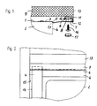
Figur 1 eine Teilansicht eines in einen Möbelumbau eingesetzten Einbaugeräts im Seitenschnitt undFigur 2 eine Teilansicht auf die Frontseite der Anordnung nachFigur 1.
- Figure 1 is a partial view of a built-in device used in a furniture conversion in side section and
- FIG. 2 shows a partial view of the front of the arrangement according to FIG. 1.
Bei einem Einbaugerät, insbesondere einem Kühl,- oder Gefrierschrank, ist auf der Oberseite 1 eines Gerätegehäuses 2 eine Haltelasche 3 festgesetzt, die im Bereich einer Frontseite 4 des Gerätegehäuses 2 in einer Stufe 5 nach unten abgesetzt ist und sich über die Frontseite 4 als Abdeckleiste 6 erstreckt. Die Stufe 5 lege sich an die betreffende obere, waagerecht verlaufende Kante 7 des Gerätegehäuses 2 an. Parallel zu dieser Stufe 5 ist die Abdeckleiste 6 mit einem senkrecht nach oben gerichteten Umbug 7 versehen, an den sich ein rechtwinklig abgebogener Rand 8 anschließt, welcher sich nach rückwärts in die Nische hinein bzw. zum Gerätegehäuse 2 hin erstreckt. Oberhalb des Umbugs 7 bzw. des Randes 8 verläuft eine waagerechte Platte als Nischendecke 9, welche die das Einbaugerät aufnehmende Nische eines Umbaumöbels 10 nach oben begrenzt. Nachdem der zwischen der Oberseite 1 und der Unterseite der Nischendecke 9 befindliche Spalt vorliegend wesentlich höher ist als der Umbug 7, ist auf der Abdeckleiste 6 eine Blendenleiste 11 festgesetzt, welche den Umbug 7 frontseitig überdeckt und nach oben hin entsprechend der Höhendifferenz überragt. Dabei ist die Blendenleiste 11 im Querschnitt L-förmig ausgebildet und überdeckt nicht nur den Umbug 7, sondern auch den Rand 8, wobei an die freien Schenkelkanten der Blendenleiste 11 Untergriffhaken 12 angeformt sind, welche die Unterkante des Umbugs 7 bzw. die rückwärtige freie Kante des Randes a umgreifen. Die Blendenleiste läßt sich dadurch auf die Abdeckleiste aufschnappen, in dem beispielsweise zuerst die Untergriffhaken 12 am Rand 8 eingehakt und anschließend der frontseitige Schenkel der Blendenleiste 11 soweit nach unten gedrückt wird, bis der dort vorgesehene Untergriffhaken auf die Abdeckleiste 6 schnappt. Die Höhe des Schenkels, der auf dem Rand 8 aufliegt, ist so abgestimmt, daß das Größtmaß der Nischenhöhe zumindest ohne merkliche Höhenverlagerung der Abdeckleiste 6 ausgeglichen wird. Der parallel zum abgewinkelten Rand 8 verlaufende Schenkel der Blendenleiste 11 liegt dann bündig an der Unterseite der darüber angeordneten Nischendecke 9 des Umbaumöbels 10 an, während der den senkrechten Umbug 7 überdeckende Schenkel der Blendenleiste 11 in einer Ebene mit der frontseitigen Stirnfläche der Nischenplatte 9 liegt. Die Abdeckleiste 6 bildet hierdurch zugleich eine Einbauschablone, und legt den Abstand der Frontseite 4 des Gerätegehäuses von der durch die Stirnfläche 13 des Umbaumöbels gebildeten Ebene fest. Dabei kann die Abdeckleiste 6 über die senkrechten Seitenkanten 14 des Gerätegehäuses 2 ein- oder beidseitig so weit hinüberragen, daß ihre Enden an den benachbarten senkrechten Seitenflächen 15 des Umbaumöbels 10 anliegen. Dann ist das Gerätegehäuse 2 auch seitlich durch die Abdeckleiste 6 in der betreffenden Nische des Umbaumöbels zentriert.In the case of a built-in device, in particular a refrigerator or freezer, a holding tab 3 is fixed on the
Daneben ist es auch möglich, die Blendenleiste als flaches Band mit einer rückseitigen, nach unten offenen Nut auszubilden, wobei die Nut die dann eine nach oben freie Kante des Umbugs übergreift. Die Nut bildet hierbei die Halterung für die Blendenleiste am Umbug.In addition, it is also possible to design the cover strip as a flat band with a groove on the back that is open at the bottom, the groove then engaging over an edge of the fold that is free at the top. The groove forms the holder for the cover strip on the fold.
Die Abdeckleiste 6 wird zusammen mit der Blendenleiste 11 durch Schrauben 16 an der Nischendecke 9 festgesetzt, wobei in der Abdeckleiste 6 und im Rand 8 fluchtende Bohrungen vorgesehen sind. Der Durchmesser der Bohrung in der Abdeckleiste 6 ist dabei größer als der Kopf der Schraube 16, während die Bohrung im Rand 8 dem Durchmesser des Gewindestücks der Schraube 16 angepaßt ist. Der Schraubenkopf legt sich so gegen den Rand 8 und spannt denselben bei festgespannter Schraube zusammen mit dem parallel darauf aufliegenden Schenkel der Blendenleiste 11 gegen die Nischendecke 9. In die Bohrung der Abdeckleiste 6 läßt sich dann eine Verschlußkappe 17 eindrücken, um Schmutzablagerungen im Bereich der betreffenden Bohrung zu vermeiden, die sonst beim Reinigen der Abdeckleiste entstehen können.The cover strip 6 is fixed together with the
Claims (7)
Applications Claiming Priority (2)
| Application Number | Priority Date | Filing Date | Title |
|---|---|---|---|
| DE4003749 | 1990-02-08 | ||
| DE4003749A DE4003749A1 (en) | 1990-02-08 | 1990-02-08 | Built-in domestic refrigeration appliance - has cover rail between appliance housing and underside of work-top extending across appliance niche |
Publications (3)
| Publication Number | Publication Date |
|---|---|
| EP0441363A2 true EP0441363A2 (en) | 1991-08-14 |
| EP0441363A3 EP0441363A3 (en) | 1992-05-27 |
| EP0441363B1 EP0441363B1 (en) | 1994-12-21 |
Family
ID=6399677
Family Applications (1)
| Application Number | Title | Priority Date | Filing Date |
|---|---|---|---|
| EP91101636A Expired - Lifetime EP0441363B1 (en) | 1990-02-08 | 1991-02-07 | Flush-mounted apparatus with cover strip |
Country Status (3)
| Country | Link |
|---|---|
| EP (1) | EP0441363B1 (en) |
| AT (1) | ATE115839T1 (en) |
| DE (2) | DE4003749A1 (en) |
Cited By (5)
| Publication number | Priority date | Publication date | Assignee | Title |
|---|---|---|---|---|
| WO2007062928A1 (en) * | 2005-11-30 | 2007-06-07 | BSH Bosch und Siemens Hausgeräte GmbH | Connection system for connecting a built-in appliance to a furniture unit and furniture unit arrangement |
| WO2007062948A1 (en) * | 2005-11-30 | 2007-06-07 | BSH Bosch und Siemens Hausgeräte GmbH | Housing for a household appliance |
| WO2007062917A1 (en) * | 2005-11-30 | 2007-06-07 | BSH Bosch und Siemens Hausgeräte GmbH | Device for covering a gap |
| US8162415B2 (en) * | 2006-04-20 | 2012-04-24 | Bsh Bosch Und Siemens Hausgeraete Gmbh | Multipart household appliance |
| EP2537440A1 (en) * | 2011-06-20 | 2012-12-26 | BSH Bosch und Siemens Hausgeräte GmbH | Plinth with supported screw |
Families Citing this family (3)
| Publication number | Priority date | Publication date | Assignee | Title |
|---|---|---|---|---|
| DE29607334U1 (en) | 1996-04-23 | 1997-08-21 | AEG Hausgeräte GmbH, 90429 Nürnberg | Refrigerator and / or freezer |
| DE19818814C2 (en) * | 1998-04-27 | 2000-08-03 | Aeg Hausgeraete Gmbh | Household appliance for installation in a furniture remodeling |
| IT202200007646A1 (en) * | 2022-04-15 | 2023-10-15 | Elica Spa | Kit for the installation of a first and second built-in appliance |
Family Cites Families (4)
| Publication number | Priority date | Publication date | Assignee | Title |
|---|---|---|---|---|
| US1690286A (en) * | 1924-03-31 | 1928-11-06 | Gen Fireproofing Co | Edge construction for furniture tops |
| DE1233550B (en) * | 1958-03-05 | 1967-02-02 | Therma Ag | Kitchen equipment |
| CH644743A5 (en) * | 1979-05-31 | 1984-08-31 | Bosch Siemens Hausgeraete | Device for fixing a built-in appliance fitted with feet in a recess of a cabinet |
| IT8034039V0 (en) * | 1980-09-26 | 1980-09-26 | Zanussi A Spa Industrie | FRAME FOR THE WORKTOP OF A HOUSEHOLD APPLIANCE. |
-
1990
- 1990-02-08 DE DE4003749A patent/DE4003749A1/en not_active Withdrawn
-
1991
- 1991-02-07 AT AT91101636T patent/ATE115839T1/en not_active IP Right Cessation
- 1991-02-07 EP EP91101636A patent/EP0441363B1/en not_active Expired - Lifetime
- 1991-02-07 DE DE59103939T patent/DE59103939D1/en not_active Expired - Fee Related
Cited By (8)
| Publication number | Priority date | Publication date | Assignee | Title |
|---|---|---|---|---|
| WO2007062928A1 (en) * | 2005-11-30 | 2007-06-07 | BSH Bosch und Siemens Hausgeräte GmbH | Connection system for connecting a built-in appliance to a furniture unit and furniture unit arrangement |
| WO2007062948A1 (en) * | 2005-11-30 | 2007-06-07 | BSH Bosch und Siemens Hausgeräte GmbH | Housing for a household appliance |
| WO2007062917A1 (en) * | 2005-11-30 | 2007-06-07 | BSH Bosch und Siemens Hausgeräte GmbH | Device for covering a gap |
| US8079652B2 (en) | 2005-11-30 | 2011-12-20 | Bsh Bosch Und Siemens Hausgeraete Gmbh | Connection system for connecting a built-in appliance to a furniture unit and furniture unit arrangement |
| US8182051B2 (en) | 2005-11-30 | 2012-05-22 | Bsh Bosch Und Siemens Hausgeraete Gmbh | Housing for a household appliance |
| US9032675B2 (en) | 2005-11-30 | 2015-05-19 | Bsh Bosch Und Siemens Hausgerate Gmbh | Device for covering a gap |
| US8162415B2 (en) * | 2006-04-20 | 2012-04-24 | Bsh Bosch Und Siemens Hausgeraete Gmbh | Multipart household appliance |
| EP2537440A1 (en) * | 2011-06-20 | 2012-12-26 | BSH Bosch und Siemens Hausgeräte GmbH | Plinth with supported screw |
Also Published As
| Publication number | Publication date |
|---|---|
| ATE115839T1 (en) | 1995-01-15 |
| DE4003749A1 (en) | 1991-08-14 |
| EP0441363A3 (en) | 1992-05-27 |
| EP0441363B1 (en) | 1994-12-21 |
| DE59103939D1 (en) | 1995-02-02 |
Similar Documents
| Publication | Publication Date | Title |
|---|---|---|
| DE3632442C2 (en) | ||
| DE3713281A1 (en) | DRAWER | |
| EP0441363B1 (en) | Flush-mounted apparatus with cover strip | |
| DE19647802C1 (en) | Switch cabinet press-moulded mounting rail | |
| EP0483589B1 (en) | Linking device for adjacent kitchen equipment | |
| DE19737489C1 (en) | Switch-cabinet design | |
| DE3417453C2 (en) | ||
| DE3144131C2 (en) | ||
| DE2948627C2 (en) | Device for the adjustable fastening of a front panel on an extendable furniture part | |
| EP4434398A1 (en) | Cupboard with illuminated recessed grip between two fronts | |
| DE3203437C2 (en) | Flush-mounted distribution boards for electrical devices | |
| DE8707366U1 (en) | Office desk | |
| DE7530601U (en) | BRACKET FOR A WALL CABINET | |
| DE4128449C2 (en) | Subrack | |
| DE19843821C2 (en) | Shower tray | |
| DE19518220A1 (en) | Pull-out device for a telecommunications equipment frame | |
| EP1093733B1 (en) | Piece of furniture | |
| DE19811752C1 (en) | Switching cabinet frame with body on pedestal for receiving different quantities of cable to be fed through | |
| DE29817470U1 (en) | Housing frames for electronic devices | |
| DE2903382A1 (en) | COOKER HOOD FOR COOKING STOVES | |
| DE2508920C2 (en) | Extractor hood | |
| DE8107393U1 (en) | "CONNECTION PROFILE FOR A SHOWER SEPARATION" | |
| DE69100860T2 (en) | Roof trim panel arrangement. | |
| EP0879573A1 (en) | Fastening element for a metal rail | |
| DE3810647A1 (en) | Connection of the housing casing and bottom part in household implements, in particular in washing machines which can be loaded from above |
Legal Events
| Date | Code | Title | Description |
|---|---|---|---|
| PUAI | Public reference made under article 153(3) epc to a published international application that has entered the european phase |
Free format text: ORIGINAL CODE: 0009012 |
|
| AK | Designated contracting states |
Kind code of ref document: A2 Designated state(s): AT CH DE FR IT LI |
|
| PUAL | Search report despatched |
Free format text: ORIGINAL CODE: 0009013 |
|
| AK | Designated contracting states |
Kind code of ref document: A3 Designated state(s): AT CH DE FR IT LI |
|
| 17P | Request for examination filed |
Effective date: 19921028 |
|
| 17Q | First examination report despatched |
Effective date: 19940303 |
|
| GRAA | (expected) grant |
Free format text: ORIGINAL CODE: 0009210 |
|
| AK | Designated contracting states |
Kind code of ref document: B1 Designated state(s): AT CH DE FR IT LI |
|
| REF | Corresponds to: |
Ref document number: 115839 Country of ref document: AT Date of ref document: 19950115 Kind code of ref document: T |
|
| REF | Corresponds to: |
Ref document number: 59103939 Country of ref document: DE Date of ref document: 19950202 |
|
| ET | Fr: translation filed | ||
| ITF | It: translation for a ep patent filed | ||
| PLBE | No opposition filed within time limit |
Free format text: ORIGINAL CODE: 0009261 |
|
| STAA | Information on the status of an ep patent application or granted ep patent |
Free format text: STATUS: NO OPPOSITION FILED WITHIN TIME LIMIT |
|
| REG | Reference to a national code |
Ref country code: CH Ref legal event code: PUE Owner name: LICENTIA PATENT- VERWALTUNGS-GMBH TRANSFER- AEG HA |
|
| 26N | No opposition filed | ||
| REG | Reference to a national code |
Ref country code: FR Ref legal event code: TP |
|
| PGFP | Annual fee paid to national office [announced via postgrant information from national office to epo] |
Ref country code: FR Payment date: 19960202 Year of fee payment: 6 Ref country code: AT Payment date: 19960202 Year of fee payment: 6 |
|
| PGFP | Annual fee paid to national office [announced via postgrant information from national office to epo] |
Ref country code: CH Payment date: 19960503 Year of fee payment: 6 |
|
| PG25 | Lapsed in a contracting state [announced via postgrant information from national office to epo] |
Ref country code: AT Effective date: 19970207 |
|
| PGFP | Annual fee paid to national office [announced via postgrant information from national office to epo] |
Ref country code: DE Payment date: 19970212 Year of fee payment: 7 |
|
| PG25 | Lapsed in a contracting state [announced via postgrant information from national office to epo] |
Ref country code: LI Effective date: 19970228 Ref country code: CH Effective date: 19970228 |
|
| REG | Reference to a national code |
Ref country code: CH Ref legal event code: PL |
|
| PG25 | Lapsed in a contracting state [announced via postgrant information from national office to epo] |
Ref country code: FR Effective date: 19971030 |
|
| REG | Reference to a national code |
Ref country code: FR Ref legal event code: ST |
|
| PG25 | Lapsed in a contracting state [announced via postgrant information from national office to epo] |
Ref country code: DE Free format text: LAPSE BECAUSE OF NON-PAYMENT OF DUE FEES Effective date: 19981103 |
|
| PG25 | Lapsed in a contracting state [announced via postgrant information from national office to epo] |
Ref country code: IT Free format text: LAPSE BECAUSE OF NON-PAYMENT OF DUE FEES;WARNING: LAPSES OF ITALIAN PATENTS WITH EFFECTIVE DATE BEFORE 2007 MAY HAVE OCCURRED AT ANY TIME BEFORE 2007. THE CORRECT EFFECTIVE DATE MAY BE DIFFERENT FROM THE ONE RECORDED. Effective date: 20050207 |