EP0441522A2 - Appareil de commande pour automobile - Google Patents
Appareil de commande pour automobile Download PDFInfo
- Publication number
- EP0441522A2 EP0441522A2 EP91300704A EP91300704A EP0441522A2 EP 0441522 A2 EP0441522 A2 EP 0441522A2 EP 91300704 A EP91300704 A EP 91300704A EP 91300704 A EP91300704 A EP 91300704A EP 0441522 A2 EP0441522 A2 EP 0441522A2
- Authority
- EP
- European Patent Office
- Prior art keywords
- neural
- neural elements
- output
- signals
- control device
- Prior art date
- Legal status (The legal status is an assumption and is not a legal conclusion. Google has not performed a legal analysis and makes no representation as to the accuracy of the status listed.)
- Granted
Links
Images


Classifications
-
- G—PHYSICS
- G01—MEASURING; TESTING
- G01S—RADIO DIRECTION-FINDING; RADIO NAVIGATION; DETERMINING DISTANCE OR VELOCITY BY USE OF RADIO WAVES; LOCATING OR PRESENCE-DETECTING BY USE OF THE REFLECTION OR RERADIATION OF RADIO WAVES; ANALOGOUS ARRANGEMENTS USING OTHER WAVES
- G01S17/00—Systems using the reflection or reradiation of electromagnetic waves other than radio waves, e.g. lidar systems
- G01S17/88—Lidar systems specially adapted for specific applications
- G01S17/93—Lidar systems specially adapted for specific applications for anti-collision purposes
- G01S17/931—Lidar systems specially adapted for specific applications for anti-collision purposes of land vehicles
-
- B—PERFORMING OPERATIONS; TRANSPORTING
- B60—VEHICLES IN GENERAL
- B60K—ARRANGEMENT OR MOUNTING OF PROPULSION UNITS OR OF TRANSMISSIONS IN VEHICLES; ARRANGEMENT OR MOUNTING OF PLURAL DIVERSE PRIME-MOVERS IN VEHICLES; AUXILIARY DRIVES FOR VEHICLES; INSTRUMENTATION OR DASHBOARDS FOR VEHICLES; ARRANGEMENTS IN CONNECTION WITH COOLING, AIR INTAKE, GAS EXHAUST OR FUEL SUPPLY OF PROPULSION UNITS IN VEHICLES
- B60K31/00—Vehicle fittings, acting on a single sub-unit only, for automatically controlling vehicle speed, i.e. preventing speed from exceeding an arbitrarily established velocity or maintaining speed at a particular velocity, as selected by the vehicle operator
- B60K31/0008—Vehicle fittings, acting on a single sub-unit only, for automatically controlling vehicle speed, i.e. preventing speed from exceeding an arbitrarily established velocity or maintaining speed at a particular velocity, as selected by the vehicle operator including means for detecting potential obstacles in vehicle path
-
- B—PERFORMING OPERATIONS; TRANSPORTING
- B60—VEHICLES IN GENERAL
- B60W—CONJOINT CONTROL OF VEHICLE SUB-UNITS OF DIFFERENT TYPE OR DIFFERENT FUNCTION; CONTROL SYSTEMS SPECIALLY ADAPTED FOR HYBRID VEHICLES; ROAD VEHICLE DRIVE CONTROL SYSTEMS FOR PURPOSES NOT RELATED TO THE CONTROL OF A PARTICULAR SUB-UNIT
- B60W30/00—Purposes of road vehicle drive control systems not related to the control of a particular sub-unit, e.g. of systems using conjoint control of vehicle sub-units
- B60W30/18—Propelling the vehicle
- B60W30/20—Reducing vibrations in the driveline
-
- B—PERFORMING OPERATIONS; TRANSPORTING
- B60—VEHICLES IN GENERAL
- B60W—CONJOINT CONTROL OF VEHICLE SUB-UNITS OF DIFFERENT TYPE OR DIFFERENT FUNCTION; CONTROL SYSTEMS SPECIALLY ADAPTED FOR HYBRID VEHICLES; ROAD VEHICLE DRIVE CONTROL SYSTEMS FOR PURPOSES NOT RELATED TO THE CONTROL OF A PARTICULAR SUB-UNIT
- B60W40/00—Estimation or calculation of non-directly measurable driving parameters for road vehicle drive control systems not related to the control of a particular sub unit, e.g. by using mathematical models
- B60W40/08—Estimation or calculation of non-directly measurable driving parameters for road vehicle drive control systems not related to the control of a particular sub unit, e.g. by using mathematical models related to drivers or passengers
- B60W40/09—Driving style or behaviour
-
- B—PERFORMING OPERATIONS; TRANSPORTING
- B60—VEHICLES IN GENERAL
- B60W—CONJOINT CONTROL OF VEHICLE SUB-UNITS OF DIFFERENT TYPE OR DIFFERENT FUNCTION; CONTROL SYSTEMS SPECIALLY ADAPTED FOR HYBRID VEHICLES; ROAD VEHICLE DRIVE CONTROL SYSTEMS FOR PURPOSES NOT RELATED TO THE CONTROL OF A PARTICULAR SUB-UNIT
- B60W50/00—Details of control systems for road vehicle drive control not related to the control of a particular sub-unit, e.g. process diagnostic or vehicle driver interfaces
-
- F—MECHANICAL ENGINEERING; LIGHTING; HEATING; WEAPONS; BLASTING
- F02—COMBUSTION ENGINES; HOT-GAS OR COMBUSTION-PRODUCT ENGINE PLANTS
- F02D—CONTROLLING COMBUSTION ENGINES
- F02D41/00—Electrical control of supply of combustible mixture or its constituents
- F02D41/02—Circuit arrangements for generating control signals
- F02D41/14—Introducing closed-loop corrections
- F02D41/1401—Introducing closed-loop corrections characterised by the control or regulation method
- F02D41/1405—Neural network control
-
- F—MECHANICAL ENGINEERING; LIGHTING; HEATING; WEAPONS; BLASTING
- F02—COMBUSTION ENGINES; HOT-GAS OR COMBUSTION-PRODUCT ENGINE PLANTS
- F02P—IGNITION, OTHER THAN COMPRESSION IGNITION, FOR INTERNAL-COMBUSTION ENGINES; TESTING OF IGNITION TIMING IN COMPRESSION-IGNITION ENGINES
- F02P5/00—Advancing or retarding ignition; Control therefor
- F02P5/04—Advancing or retarding ignition; Control therefor automatically, as a function of the working conditions of the engine or vehicle or of the atmospheric conditions
- F02P5/045—Advancing or retarding ignition; Control therefor automatically, as a function of the working conditions of the engine or vehicle or of the atmospheric conditions combined with electronic control of other engine functions, e.g. fuel injection
-
- G—PHYSICS
- G01—MEASURING; TESTING
- G01L—MEASURING FORCE, STRESS, TORQUE, WORK, MECHANICAL POWER, MECHANICAL EFFICIENCY, OR FLUID PRESSURE
- G01L23/00—Devices or apparatus for measuring or indicating or recording rapid changes, such as oscillations, in the pressure of steam, gas, or liquid; Indicators for determining work or energy of steam, internal-combustion, or other fluid-pressure engines from the condition of the working fluid
- G01L23/22—Devices or apparatus for measuring or indicating or recording rapid changes, such as oscillations, in the pressure of steam, gas, or liquid; Indicators for determining work or energy of steam, internal-combustion, or other fluid-pressure engines from the condition of the working fluid for detecting or indicating knocks in internal-combustion engines; Units comprising pressure-sensitive members combined with ignitors for firing internal-combustion engines
- G01L23/221—Devices or apparatus for measuring or indicating or recording rapid changes, such as oscillations, in the pressure of steam, gas, or liquid; Indicators for determining work or energy of steam, internal-combustion, or other fluid-pressure engines from the condition of the working fluid for detecting or indicating knocks in internal-combustion engines; Units comprising pressure-sensitive members combined with ignitors for firing internal-combustion engines for detecting or indicating knocks in internal combustion engines
- G01L23/225—Devices or apparatus for measuring or indicating or recording rapid changes, such as oscillations, in the pressure of steam, gas, or liquid; Indicators for determining work or energy of steam, internal-combustion, or other fluid-pressure engines from the condition of the working fluid for detecting or indicating knocks in internal-combustion engines; Units comprising pressure-sensitive members combined with ignitors for firing internal-combustion engines for detecting or indicating knocks in internal combustion engines circuit arrangements therefor
-
- B—PERFORMING OPERATIONS; TRANSPORTING
- B60—VEHICLES IN GENERAL
- B60W—CONJOINT CONTROL OF VEHICLE SUB-UNITS OF DIFFERENT TYPE OR DIFFERENT FUNCTION; CONTROL SYSTEMS SPECIALLY ADAPTED FOR HYBRID VEHICLES; ROAD VEHICLE DRIVE CONTROL SYSTEMS FOR PURPOSES NOT RELATED TO THE CONTROL OF A PARTICULAR SUB-UNIT
- B60W30/00—Purposes of road vehicle drive control systems not related to the control of a particular sub-unit, e.g. of systems using conjoint control of vehicle sub-units
- B60W30/18—Propelling the vehicle
- B60W30/20—Reducing vibrations in the driveline
- B60W2030/206—Reducing vibrations in the driveline related or induced by the engine
-
- B—PERFORMING OPERATIONS; TRANSPORTING
- B60—VEHICLES IN GENERAL
- B60W—CONJOINT CONTROL OF VEHICLE SUB-UNITS OF DIFFERENT TYPE OR DIFFERENT FUNCTION; CONTROL SYSTEMS SPECIALLY ADAPTED FOR HYBRID VEHICLES; ROAD VEHICLE DRIVE CONTROL SYSTEMS FOR PURPOSES NOT RELATED TO THE CONTROL OF A PARTICULAR SUB-UNIT
- B60W50/00—Details of control systems for road vehicle drive control not related to the control of a particular sub-unit, e.g. process diagnostic or vehicle driver interfaces
- B60W2050/0001—Details of the control system
- B60W2050/0002—Automatic control, details of type of controller or control system architecture
-
- B—PERFORMING OPERATIONS; TRANSPORTING
- B60—VEHICLES IN GENERAL
- B60W—CONJOINT CONTROL OF VEHICLE SUB-UNITS OF DIFFERENT TYPE OR DIFFERENT FUNCTION; CONTROL SYSTEMS SPECIALLY ADAPTED FOR HYBRID VEHICLES; ROAD VEHICLE DRIVE CONTROL SYSTEMS FOR PURPOSES NOT RELATED TO THE CONTROL OF A PARTICULAR SUB-UNIT
- B60W50/00—Details of control systems for road vehicle drive control not related to the control of a particular sub-unit, e.g. process diagnostic or vehicle driver interfaces
- B60W2050/0001—Details of the control system
- B60W2050/0043—Signal treatments, identification of variables or parameters, parameter estimation or state estimation
- B60W2050/0057—Frequency analysis, spectral techniques or transforms
-
- B—PERFORMING OPERATIONS; TRANSPORTING
- B60—VEHICLES IN GENERAL
- B60W—CONJOINT CONTROL OF VEHICLE SUB-UNITS OF DIFFERENT TYPE OR DIFFERENT FUNCTION; CONTROL SYSTEMS SPECIALLY ADAPTED FOR HYBRID VEHICLES; ROAD VEHICLE DRIVE CONTROL SYSTEMS FOR PURPOSES NOT RELATED TO THE CONTROL OF A PARTICULAR SUB-UNIT
- B60W2540/00—Input parameters relating to occupants
- B60W2540/30—Driving style
-
- F—MECHANICAL ENGINEERING; LIGHTING; HEATING; WEAPONS; BLASTING
- F02—COMBUSTION ENGINES; HOT-GAS OR COMBUSTION-PRODUCT ENGINE PLANTS
- F02B—INTERNAL-COMBUSTION PISTON ENGINES; COMBUSTION ENGINES IN GENERAL
- F02B75/00—Other engines
- F02B75/02—Engines characterised by their cycles, e.g. six-stroke
- F02B2075/022—Engines characterised by their cycles, e.g. six-stroke having less than six strokes per cycle
- F02B2075/027—Engines characterised by their cycles, e.g. six-stroke having less than six strokes per cycle four
-
- F—MECHANICAL ENGINEERING; LIGHTING; HEATING; WEAPONS; BLASTING
- F02—COMBUSTION ENGINES; HOT-GAS OR COMBUSTION-PRODUCT ENGINE PLANTS
- F02D—CONTROLLING COMBUSTION ENGINES
- F02D41/00—Electrical control of supply of combustible mixture or its constituents
- F02D41/02—Circuit arrangements for generating control signals
- F02D41/14—Introducing closed-loop corrections
- F02D41/1401—Introducing closed-loop corrections characterised by the control or regulation method
- F02D2041/1433—Introducing closed-loop corrections characterised by the control or regulation method using a model or simulation of the system
-
- F—MECHANICAL ENGINEERING; LIGHTING; HEATING; WEAPONS; BLASTING
- F16—ENGINEERING ELEMENTS AND UNITS; GENERAL MEASURES FOR PRODUCING AND MAINTAINING EFFECTIVE FUNCTIONING OF MACHINES OR INSTALLATIONS; THERMAL INSULATION IN GENERAL
- F16H—GEARING
- F16H61/00—Control functions within control units of change-speed- or reversing-gearings for conveying rotary motion ; Control of exclusively fluid gearing, friction gearing, gearings with endless flexible members or other particular types of gearing
- F16H2061/0075—Control functions within control units of change-speed- or reversing-gearings for conveying rotary motion ; Control of exclusively fluid gearing, friction gearing, gearings with endless flexible members or other particular types of gearing characterised by a particular control method
- F16H2061/0081—Fuzzy logic
-
- F—MECHANICAL ENGINEERING; LIGHTING; HEATING; WEAPONS; BLASTING
- F16—ENGINEERING ELEMENTS AND UNITS; GENERAL MEASURES FOR PRODUCING AND MAINTAINING EFFECTIVE FUNCTIONING OF MACHINES OR INSTALLATIONS; THERMAL INSULATION IN GENERAL
- F16H—GEARING
- F16H61/00—Control functions within control units of change-speed- or reversing-gearings for conveying rotary motion ; Control of exclusively fluid gearing, friction gearing, gearings with endless flexible members or other particular types of gearing
- F16H2061/0075—Control functions within control units of change-speed- or reversing-gearings for conveying rotary motion ; Control of exclusively fluid gearing, friction gearing, gearings with endless flexible members or other particular types of gearing characterised by a particular control method
- F16H2061/0084—Neural networks
-
- F—MECHANICAL ENGINEERING; LIGHTING; HEATING; WEAPONS; BLASTING
- F16—ENGINEERING ELEMENTS AND UNITS; GENERAL MEASURES FOR PRODUCING AND MAINTAINING EFFECTIVE FUNCTIONING OF MACHINES OR INSTALLATIONS; THERMAL INSULATION IN GENERAL
- F16H—GEARING
- F16H61/00—Control functions within control units of change-speed- or reversing-gearings for conveying rotary motion ; Control of exclusively fluid gearing, friction gearing, gearings with endless flexible members or other particular types of gearing
- F16H2061/0075—Control functions within control units of change-speed- or reversing-gearings for conveying rotary motion ; Control of exclusively fluid gearing, friction gearing, gearings with endless flexible members or other particular types of gearing characterised by a particular control method
- F16H2061/0087—Adaptive control, e.g. the control parameters adapted by learning
-
- Y—GENERAL TAGGING OF NEW TECHNOLOGICAL DEVELOPMENTS; GENERAL TAGGING OF CROSS-SECTIONAL TECHNOLOGIES SPANNING OVER SEVERAL SECTIONS OF THE IPC; TECHNICAL SUBJECTS COVERED BY FORMER USPC CROSS-REFERENCE ART COLLECTIONS [XRACs] AND DIGESTS
- Y10—TECHNICAL SUBJECTS COVERED BY FORMER USPC
- Y10S—TECHNICAL SUBJECTS COVERED BY FORMER USPC CROSS-REFERENCE ART COLLECTIONS [XRACs] AND DIGESTS
- Y10S706/00—Data processing: artificial intelligence
- Y10S706/902—Application using ai with detail of the ai system
- Y10S706/903—Control
- Y10S706/905—Vehicle or aerospace
Definitions
- This invention relates to a control device for an automobile and particularly to a control device for an automobile applying neural network theory.
- a pre-programmed control device currently in use with a digital computer is typically used for fuel control in an automobile. Examples are disclosed in, inter alia , U.S. Patent No. 4,542,730 and U.S. Patent No. 4,785,783 and in these prior art devices, a number of sensors have been used for detecting operational states of the engine, transmission, brake, vehicle height, suspension and the like. In addition, the outputs from each of these sensors are each used for a particular control variable or as a correction variable for a learning control.
- An object of this invention is to provide a control device for an automobile which at least partially mitigates the above disadvantages and problems.
- An object of a feature of this invention is to provide an output signal from a sensor transformed into a plurality of signals, which are then inputted to an input layer of hierarchical neural elements, and the inputted signals therein are weighted according to weighting factors so as to generate a signal which is to be used as a parameter to determine control variables for control actuators in the automobile.
- An object of another feature of this invention is that each control actuator of the automobile is controlled based on the results of the final outputs from hierarchical neural elements, an input layer of which was inputted with the output signals from a plurality of sensors.
- a control device for an automobile having at least one sensor adapted to detect an operational state of said automobile, and an actuator for controlling said operational state
- said control device including a hierarchical group of neural elements adapted to receive an output signal from said at least one sensor, modifying means for adaptively controlling the neural elements in accordance with a desired parameter and a control means for receiving an output signal from said group of neural elements for controlling said actuator.
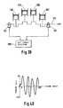
- the control device shown in Figure 1 is used with an automobile internal combustion engine 1 having an inlet air suction pipe 20 and an exhaust pipe 21.
- a fuel injection valve 6 is provided on a portion of the suction pipe 20 to supply fuel to the engine.
- Intake air flow is measured with an air flow sensor 22, and its measurement is inputted to a control circuit 2.
- the control circuit 2 also receives signals from a crankshaft rotation angle detector 3, an oxygen sensor 4 (and outputs from sensors of other engine parameters desired to be monitored), then supplies output signals, for example, to an ignition plug 7 via an ignition coil 5.
- a knock sensor 8 for detecting mechanical vibration of the engine caused by poor detonation due, for example, to poor fuel or incorrect ignition timing.
- the signal from the knock sensor 8 is inputted to a sample and hold circuit 11 over line 10 via a high pass filter and amplifier 9, the input signal being given in time series to the sample and hold circuit 11.
- the sample and hold circuit 11 samples the time series signals on line 10 at a given time interval and holds the signals to provide a spatial multi-variable signal consisting of 12a, 12b, 12c, ..., 12n bits in sequence of input order, so as to be inputted to the input layer of a neural computer 13.
- the output voltage on line 14 from the neural computer is output in proportion to the intensity of engine knocking, and is converted from analog to digital signals in an A/D converter of the control circuit 2, then is used to control ignition timing.
- the signal on line 15 from the control circuit 2 is used for controlling the sample and hold circuit 11.
- a control flow sequence of ignition timing ⁇ ig is shown.
- a primary or basic ignition timing ⁇ o is fetched from a memory map in control circuit 2 and is read in Step 25.
- ⁇ o is determined by the number of engine revolutions and the load (or fuel injection period, throttle valve opening angle or the like).
- an ignition timing ⁇ is calculated as where ⁇ is a calculated value for correction.
- ⁇ ig is set to start ignition.
- the intensity of knocking is measured from the output on line 14 from the neural computer 13.
- correction quantity ⁇ is calculated, wherein ⁇ is calculated in accordance with the magnitude of the output on line 14, from - ⁇ (delay angle) to + ⁇ (advance angle).
- the cylinder of an engine has a natural frequency due to engine knocking as taught by Draper as follows.
- knocking is determined by a relationship between B and C. Thereby, the knocking frequency varies according to the diameter of the cylinder bore.
- Figure 3 shows the relationship between frequencies and outputs for a different type of knock sensor 8.
- the output thereof is kept constant throughout the whole frequency range, though the magnitude of its output is very small.
- the output thereof becomes very large at a specific frequency.
- a wide-range resonant type knock sensor though an amplitude of its output is smaller than that of the resonant type knock sensor, its resonance range extends to a wider range of the frequency.
- Figure 4 shows ratios of cylinder pressures at knocking to those without knocking relative to the frequency. It is shown in Figure 4 that the pressure ratios become large at 7.9KHz, 13.8KHz, 18.5KHz, and 22KHz, thus exemplifying large pressure increases during knocking which is widely dispersed in frequency.
- a wide range resonant type knock sensor capable of detecting many knocking frequencies is preferred.
- the resonant type knock sensor may alternatively be used by setting its resonance point in accordance with the cylinder bore diamter.
- Figures 5(a) and (b) show the relationship between engine crank angle and knock sensor output.
- Figure 5(a) shows the case of a resonant type knock sensor. Knocking phenomena are caused by reciprocating pressure waves travelling inside the cylinder, which are genrated by self-detonation of mixtures due to an increase in cylinder pressure during combustion of mixtures in the cylinder. Therefore, knocking occurs delayed in time after the ignition.
- the resonant type sensor its output is generated in the range of resonant frequencies.
- Figure 5(b) shows the case of a wide range resonance type knock sensor. As shown in the Figure 5(b), the sensor output is output as a synthesized wave of many frequencies. In both cases, knocking is initiated, with ignition as the starting point, but delayed in time from ignition.
- a sampling start signal may be generated with the instant of ignition as its starting point.
- the sampling period of the sample and hold circuit 11 is advantageously set at about one tenth of the maximum measurement frequency for a wide range resonant type knock sensor. In other words, it is required to measure knock signals at predetermined intervals (preferably one tenth maximum measurement frequency) and again measure the knock signals at a next cylinder firing stroke of the cylinder of concern, the signals passing through the neural computer and then being compared to remove the effect of the noise component.
- the sampling period may be satisfactory if the minimum measurement frequency is less than the period of a minimum cycle, the sampling periods being less than the minimum measurement frequency.
- sampling is preferably taken for more than one cycle at one tenth of the resonance frequency, as stated above.
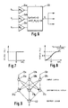
- a neural element 23 a constitutuent of a neural computer 13 is shown in Figure 6 having inputs O k ' O j and O l multiplied in the neural element with weighting factor, W ik , W ij , W il respectively, and the output O i is expressed as follows.
- ⁇ is a threshold.
- the output O i is then inputted to the next neural element.
- the neural computer has neural elements arranged in an input layer, an intermediate layer and an output layer.
- neural elements 30a, 30b and 30c receiving input signals on lines 12a, 12b and 12c respectively from the sample hold circuit 11 in sequence.
- the output from the neural element 30a is inputted to neural elements 31a, 31b and 31c in the intermediate layer, after being multiplied with respective weighting factors.
- the output signal from the neural elements 30b and 30c are inputted to the neural elements 31a, 31b and 31c in the intermediate layer, after being multiplied with respective weighting factors.
- the neural elements 31a, 31b and 31c have a threshold value ⁇ , which is subtracted from the respective outputs of the neural elements 31a, 31b, 31c, the various results are multiplied by various weighting factors and then inputted to a neural element 32 in the output layer, output from neural element 32 having a threshold value ⁇ 2 which is subtracted from the output signal of neural element 32.
- Step 33 actual knock signal data is inputted to the input layer. Then it is judged in Step 34, whether data outputted to the output layer is correct. If yes, advance is made to Step 35, wherein the weighting factor of a correct solution route is increased. Similarly, in such a situation the thresholds ⁇ 1 and ⁇ 2 may alternatively be decreased.
- Step 37 A difference from the correct solution is judged in Step 37, and when the error is below a predetermined amount, the flow sequence is completed. If the error is above the predetermined level, the sequence returns to Step 34, where weighting factors and thresholds are repeatedly readjusted until the error determined in Step 37 is acceptable.
- the number of input elements is one cycle of sensor output waveform maximum frequency divided by the sampling period.
- the configuration of these elements is shown in Figure 11.
- the input layer is composed of 30 neural elements, respective outputs thereof being inputted to the three neural elements in the intermediate layer.
- the outputs from the intermediate layer are inputted to one output layer neural element.
- FIG. 11 is one of the embodiments of the present invention, wherein detection precision may be further improved by increasing the number of neural elements in the input layer and the intermediate layer.
- Figures 12 to 14 show engineering arrangements of the neural element 23 shown in Figure 6.
- Figure 12 shows an operational amplifier having amplification factor A
- Figures 13 and 14 show a transconductance amplifier having a gain 6, and an inverter, respectively. In each case, the following explanation applies.
- Figures 15 and 16 show configurations of the coupling transistors in the input stages shown in Figures 12 and 13.
- Figure 15 is an example showing bipolar transistors
- Figure 16 is an example showing CMOS transistors.
- 16 KB, DB,KM and DM are respective constants
- I EE and I SS are output values.
- FIGs 17 to 19 there are shown block diagrams for engineeringly obtaining weighting factors for the neural element 23.
- the triode region of an FET was used where K is a constant and R is input resistance.
- a transconductance amplifier was used where R is input resistance and g m is gain, while in Figure 19 an array of 4 bit capacitors was used where c denotes capacitance and d denotes digital input.
- Figure 20 shows in block schematic form an arrangement for storing weighting factors obtained by learning.
- the weighting factors which are stored in a memory 40 of the computer in the control circuit 2 are converted to analog signals in a D/A converter 41 for driving an FET.
- Figure 21 shows another exemplary embodiment using a resonant type knock sensor 8.
- Time series signals from the knock sensor 8 are transformed into spatial multi-variable signals in the sample and hold circuit 11, the output signals from which are designated as being on lines 12a - 12f.
- These signal lines 12a - 12f are inputted to a neural computer having an input layer and an output layer having output lines 43a - 43f, wherein the numbers of neural elements in the input layer and the output layer are set to be equal.
- a sampling cycle is set to be 1/4 of the resonant frequency, and the sampling time is the same as the resonant frequency.
- the signal at line 43a is thus minus the components of the resonant frequency, and therefore consists mostly of noise components.
- Figure 22 shows respective signals in each portion at the various lines of Figure 21.
- Figure 22(a) shows input signals 12a - 12f;
- Figure 22b shows the noise signals 43c - 43f;
- Figure 22(c) shows the resonant frequency signals 44a - 44f.
- the sampling was taken at a 1/4 cycle of the resonant frequency. However, by sampling at a smaller cycle, measurement precision can be improved.
- Figure 23 is a schematic diagram of an engine control device using a neural network.
- Various object values are inputted to a neural controller 50, and the resultant output is applied to an engine 51, which is the object of control. The particular condition being controlled in the engine is then fed back to the neural controller 50.
- routines by an error feedback device 52 are for correcting a weighting factor W in the neural network of the neural controller 50, or a transformation function for neural elements.
- the error feedback routines detect differences between the objective values and the actual values representing engine state, especially when the differences are great in the manner described above in relation to Figures 9 and 10.
- the arrangement shown in Figure 23 is a system for controlling air-fuel ratio state (condition) in an engine.
- An objective value r for the air-fuel ratio of the engine is outputted by a controller 53 to the neural controller 50 and the error feedback device 52.
- various quantities of engine state such as cooling water temperature Tw, the number of engine revolutions N, engine input air flow (indicative of load) Qa and the like are also inputted to the neural controller 50.
- An open period of a fuel injection valve (time T) is outputted from the neural controller 50. Given the time T, the engine 51 outputs a resultant actual air-fuel ratio (A/F) ⁇ .
- the A/F ratio ⁇ is fed back to the neural controller 50 and to the error feedback device 52.
- the error feedback device 52 determines the error difference between the objective value r, and the actual value ⁇ . If there is a large difference of error, the configuration of the neural controller 50 is estimated to be inadequate, thus, demanding action to be taken for its reconfiguration.
- This reconfiguration can be executed through rewriting weighting factors in the neural network, or by transformation functions (Sigmoid Functions or the like), in the manner described hereinabove.
- FIG 24 the configuration of such a neural network is shown, which consists of an input layer i, an intermediate layer j and an output layer k.
- the output O j from the intermediate layer is expressed as follows.
- f is a transformation function, for instance, such as a Sigmoid function given hereinbefore.
- An output T is expressed as follows.
- Figure 25(a) shows the mode of function transformation in the intermediate layer j.
- O j (1) shows the state at the first neural element in the intermediate layer, the sum of the inputs to which neural element is The output of this function is transformed into a non-linear function to be O j (1).
- the following outputs in the intermediate layer are determined likewise to be O j (2), O j (3), ...
- the sum of the outputs from the intermediate layer becomes an input to the neural element in the output layer as shown in Figure 25(b).
- it is also transformed so as to yield an output T.
- the output T is then given to the engine 51.
- T is required to be determined as a time delay in transporting fuel during a transient state of the engine, and T may readily be given by choosing a desirable value in the functions in Figure 25(a).
- the neural controller 50 may be considered to be a model simulating the internal state of the engine 51, wherein, very complicated phenomena such as the delay in transport of fuel and the like which are hard to describe mathematically can be corrected and compensated through repeated reconfiguration by a learning process, as will be described later herein.
- FIG. 26(a) The mode of reconfiguration in a neural network is shown in Figure 26(a), wherein an example is given which was obtained by rewriting a weighting factor for a neural element.
- the original state before learning is indicated by broken line (A) with its output being O j (1).
- W 1i When its weighting factor is rewritten to W 1i , through learning, it changes to a state as indicated by chain broken line (B) with its output being O j (1)'.
- an output different from the original can be obtained by rewriting the weighting factors.
- Figure 26(b) graphically shows another method for rewriting a transformation function so that a curve (A) shown in solid line in the Figure 26(b) obtained before learning can be changed to a curve (B) (shown in broken line) after learning by changing the threshold value.
- a curve (A) shown in solid line in the Figure 26(b) obtained before learning can be changed to a curve (B) (shown in broken line) after learning by changing the threshold value.
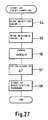
- FIG. 27 A flowchart of learning in the neural controller 50 for the arrangement of Figure 23 is shown in Figure 27.
- a learning operation is activated at every sampling of ⁇ .
- an objective value is read.
- Step 55 the actual A/C ratio value ⁇ is read.
- Step 56 an error e is obtained.
- Step 57 a correction quantity of T, i.e., ⁇ T, is calculated in Step 57. Then, in Step 58, a modification program is started.
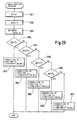
- FIG. 29 shows an alternative modification program.
- Steps 591 ⁇ 597 are the same as in Figure 28, but in Steps 603 ⁇ 607 the functions f1 to f5 are modified or corrected in dependence upon the magnitude of ⁇ E.
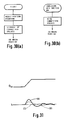
- Figures 30(a), (b) a method for storing and reading modification or correction variable quantities is shown. As shown in Figure 30(a), after a modification program is completed, modified quantities (weighting factors or functions) are promptly stored in a battery backed up memory in order to retain learning effects. These modification quantities thus stored are fetched and read instantly after an ignition key switch is turned on ( Figure 30(b)).
- Figure 31 shows an example of the effect of learning. Variations in ⁇ , i.e., air-fuel ratio, are shown relative to the acceleration throttle opening angle ⁇ ac. It is shown that the variation in ⁇ becomes smaller through learning steps (shown in the lower figure) by lines from (A) to (C).
- Figure 32 shows an example of a multi-variable control device using the present invention.
- objective values of an air-fuel ratio A/F, a torque T and an acceleration g are given to a neural controller 50 from a controller 53.
- An injection valve opening time T inj , an ignition timing T ig , a throttle valve opening angle ⁇ th , a gear position in a transmission P tr , and a line pressure OP l are output from the neural controller 50 to an automobile 60.
- a neural network 50 The construction of a neural network 50 is shown in Figure 33.
- various quantities of engine state such as water temperature, intake air flow, engine revolutions, load and the like are inputted to the input layer for evaluation, transferred through intermediate layer j and output from layer k.
- Figure 34 shows an arrangement of sensors on an automobile including a controller 61 which includes the neural controller 50.
- the controller 61 receives inputs from a throttle opening angle ( ⁇ ac) sensor 62, an air flow sensor 63, a torque sensor 64, an acceleration sensor 65, and provides outputs to an actuator 67 which electrically activates a throttle value 66, an ignition signal on line 70 to an ignition coil 69, an open value signal on line 72 to an injection valve 71, a gear position signal on line 74 to a transmission 73, and a hydraulic line pressure control signal OP1 (not shown in the Figure) for controlling the transmission.
- ⁇ ac throttle opening angle
- FIG. 35 An example of a determining means for the objective values A/F, T, and g is given in Figure 35, wherein an acceleration throttle opening angle ⁇ ac reflecting a driver's intention for action is used as an input so that the torque T and acceleration g may be accordingly determined.
- Representing the change in ⁇ ac with time is ⁇ as is shown in Figure 35, from ⁇ ac and ⁇ objective values may be retrieved from three different maps representative of A/F, T and g, respectively.
- FIG. 36 Another example of determining objective values is shown in Figure 36, wherein a pair of neural controllers 50(A) and 50(B) are employed.
- the neural controller 50(A) inputs are received from an acceleration throttle opening angle ⁇ ac sensor, a braking angle ⁇ br sensor, and a travelling speed V sensor, such that a driving environment for the automobile is evaluated. That is, it is evaluated whether the automobile is passing through an urban district, a highway, a traffic jam, a rough road (gravel, wet, or frozen), climbing a hill, or going down a slope, so as to determine optimum objective values to be given as torque and acceleration corresponding to such environments.
- These objective values thus determined are given to the neural controller 50(B) so as to control the various components in the car as described above.
- the example in Figure 32 explains a case where an automobile is controlled more in accordance with a driver's intended action
- the example in Figure 36 explains a case where the automobile is controlled to achieve an optimum driving performance matched to the environment.
- FIG. 37(a) there is an automobile 115, a vehicle control device 116, and an engine crankshaft or output torque sensor 117.
- the engine crankshaft or output torque is detected by the engine crankshaft or output torque sensor 117, and is evaluated in the vehicle control device 116 whether the torque is the same as the objective torque. If it is not the same as the objective torque, a parameter for varying the output torque of the engine 115 is changed and controlled so as to yield an output the same as the objective torque.
- FIG. 37(b) A control flow block diagram for the arrangement of Figure 37(a) is shown in Figure 37(b).
- An objective torque map is stored in a memory 118.
- the memory 118 is a RAM which is backed up, for example, by a ROM or a battery.
- the objective torque is, for example, a map of the engine revolutions and the load torque (shown in Figure 38). Instead of the load torque, a basic fuel injection pulse width, an intake pressure, a throttle valve opening angle or acceleration valve opening angle may alternatively be used.
- the objective torque is compared in a comparison means 119 with the actual engine crankshaft torque of the engine.
- a parameter for varying the output torque is modified in a torque modification means 122 so as to change the output torque from the engine 115.
- a means for modifying the torque the throttle valve opening angle, amount of fuel, or ignition timing may be modified.
- the output torque of the engine is detected by a torque detection means 121.
- Figure 39 shows an engine shaft torque detection means.
- An engine crankshaft 103 interconnects, for example, four pistons 100, the number of pistons not being limited thereto in this invention.
- a sensor 101 and a sensor 102 On opposing ends of the crankshaft are installed a sensor 101 and a sensor 102 to detect rotation angles at the respective ends of the crankshaft. Signals from the sensors 101 and 102 are processed in an output torque detection means 108.
- engine crankshaft torque output or horsepower can be detected by detecting the torsional angle of the crankshaft.
- FIG 40 an example of the results of the measurements of the output torque for a single cylinder internal combustion engine are shown.
- the output torque is shown to undergo a complicated variation with change of the crank angle because of a synthesized effect of combustion pressure and cylinder inertial force. Further, in a multi-cylinder internal combustion engine, the detection of the engine output torque is more difficult because of the inclusion of synthesized output torque between each cylinder.
- Figure 41(a) to (c) shows examples of sensor outputs.
- Sensor 101 and sensor 102 are, for example, a gear wheel and an electromagnetic pick-up.
- signals such as shown in Figure 41(a) and (b) are output from the sensors 101 and 102 respectively.
- a phase difference between the two signals of sensors 101, 102 is obtained as a signal shown in Figure 41(c).
- the phase difference corresponds to the torsional angle of the crankshaft.
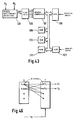
- Figure 43 shows an exemplary configuration of the present invention.
- the outputs ⁇ a and ⁇ from two sensors are inputted to a circuit 120, wherein their phase difference ⁇ is obtained.
- the phase difference ⁇ is then inputted to a peak hold circuit 106, peak-held signals thereof are then fed to a neural computer 107.
- the peak hold circuit 106 is provided one for each input layer of the neural computer. Signals to be inputted to each input layer of the neural computer are given in time series.
- a sampling period is set from one to thirty degrees in terms of a crank rotation angle.
- a CPU 108 is provided for performing various operations which is connected to a ROM 109 for reading programs, a battery backed-up RAM 110 for storing learning parameters in the neural computer, a RAM 111 for executing programs and the like, and an A/D converter 121 to input analog data.
- FIG. 44 Another embodiment of the present invention is shown in Figure 44.
- a phase difference signal is converted to a digital signal in an A/D converter 118.
- the converted digital signal is then stored in a RAM 112, wherein A/D converted values are stored in a time series order in the RAM memory cells.
- the data stored in the RAM 112 is inputted to the neural computer 107 and fetch commands to the RAM 112 to read data in time series order are controlled by the CPU 108.
- Such a configuration can be made compact in size because there is no need for a peak hold circuit to fetch data as required in the arrangement of Figure 43.
- digitalized signals they can be readily processed.
- Figure 45 shows still another embodiment of the present invention, wherein fetch and read command of data to a RAM 112 is controlled, not by the main CPU 108, but by another CPU 113 (smaller in scale than the main CPU); for instance, 8 bits are sufficient in CPU 118 as against 83 bits of the main CPU 108.
- fetch and read command of data to a RAM 112 is controlled, not by the main CPU 108, but by another CPU 113 (smaller in scale than the main CPU); for instance, 8 bits are sufficient in CPU 118 as against 83 bits of the main CPU 108.
- Figure 46 shows the basic operation of a neural computer.
- n X (x1, x2, ..., x n )
- a neural field F receiving external signals is supposed to be uniform in spatial configuration, and its relative coupling method to be of a mutually restraining type.
- the output from the neuron induces other neurons in its vicinity also to generate signals, but to restrain other neurons located a little remotely from generating signals.
- each neuron when it comes into contact with an input signal x, receives its signal through its coupling load vector S, consequently receiving an intensity of stimulation of a total inner product expressed as follows.
- an intensity of the signal received at a second neuron s expressed by s2x1+s2x2+s2x3+s2x4+ ............+s2x n
- an intensity of the signal received at an i th neuron will be s i x1+s i x3+s i x4 ............+s i x n
- an output torque Te can also be obtained from a phase difference ⁇ cr, if W ij in the neural computer is predetermined and optimized by obtaining the output torque during operation of an internal combustion engine such as by a torque sensor.
- the data of W ij obtained through learning is stored in a battery backup memory.
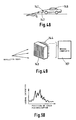
- a light emitting device 141 forming a forward facing beam, and a photoreceptor 142 for receiving light rays emitted by device 141 after the rays have been scattered by a road.
- the light emitting device may be, for example, a laser or an infra-red diode and the photoreceptor may be a phototransistor or a photodiode.
- a plurality of photoreceptors 144 may be arranged in a two-dimensional array as shown in Figure 49 and signals from the photoreceptors 144 are applied to the input layer of the neural computer 107.
- signal intensity varies according to the location of each photoreceptor. Further, signal intensity patterns vary, for instance, in dependence upon road conditions (dry, wet or frozen etc.), or the size or shape of an obstacle. In other words, through processing received data in the neural computer as above described, sizes of obstacles and various road conditions can be detected very quickly.
- these are predefined to the neural computer for processing and learning so as to optimize weighting factors and threshold values in the neural computer.
- the existence of an obstacle and road conditions can be comprehended so as to issue an early warning to a driver in good time or alternatively to optimize operational parameters.
- Figure 51 shows another apparatus for detecting the road conditions.
- a laser beam (not shown) emitted from the front of an automobile is reflected from the road and is received onto a detector 143 through lenses 147 and filters 148 which extrapolates the required light wavelength from extraneous light so as to thereby examine the shape and intensity of a reflected light ray. Based on the data it is possible to find out road surface conditions and slant or curvature of the road in front of the automobile.
- the signal 199 is obtained by subtracting a crankshaft frontal end angle signal 196 and a crankshaft rear end (ring gear end) angle signal 197 in a subtractor 195. Thereby, the signal 199 is the torsional angle of the crankshaft, indicative of the engine output.
- Output 201 from the adder 200 is inputted to a sample and hold circuit 210, wherein time series signals are transformed into spatial multi-variable series to be inputted to the input layer of a neural computer 220.
- An output 221 from the neural computer 220 is a knocking signal and an output 222, is an engine output signal.
- Figure 53 shows an embodiment of the present invention as applied to the measurement of deterioration of a catalyst 230 in a catalytic converter.
- Outputs from an O2 sensor 231 in the up-stream side of the catalyst 230 and another O2 sensor 232 in the down-stream side of the catalyst are inputted to a subtractor 233 and the output 237 thereof is then inputted to a sample and hold circuit 234.
- Output from circuit 234 is inputted to a neural computer 235 for computation therein, so as to yield a catalyst deterioration output 236.
- FIG. 54 shows another embodiment of the present invention applied to the measurement of catalyst deterioration.
- a neural computer 240 has an input signal on line 246 from an O2 sensor 231 positioned in the up-stream of the catalyst, a signal on line 247 from another O2 sensor 245 in the down-stream from the catalyst, an engine revolution signal 242, and a throttle opening signal on line 244.
- the neural computer outputs a catalyst deterioration signal on line 241.
- an engine intake air flow signal or a suction pipe pressure may be used.
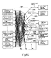
- Figure 55 shows still another embodiment of the present invention.
- automotive information such as the number of engine revolutions, knock signals, water temperature, lubricant temperature, air flow, gear position, travelling speed, throttle valve opening, damping positions of suspensions, vibration of car body, etc.
- a final output mode is provided in the neural network 300.
- weighting factors W1, W2 and W3 are changed so as to match the final output with the comfort index.
- Intermediate outputs 301a - 305a are inputted to the final stage of the neural network, while intermediate outputs 301b - 305b are inputted as objective values respectively to an air-fuel ratio control, an ignition timing control, a transmission control, a suspension control, and a throttle valve control.
- an air-fuel ratio control an ignition timing control
- a transmission control a transmission control
- a suspension control a throttle valve control
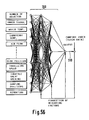
- Figure 56 shows a still further embodiment of the present invention, which can be used as a detector of the comfort index.
- a neural network 300 Into a neural network 300 are inputted the number of engine revolutions, knock signals, water temperature, lubricant temperature, air flow, gear position, travelling speed, throttle valve opening, damping positions of suspension, and vibration of car body.
- the output from the neural network 300 is compared with a comfort index as tutor data throughout a learning process by varying weighting factors.
- the output 310 indicates the value of the comfort index.
- weighting factors are varied to yield different comfort index suited to his preference.
- output signals from one or more sensors after being converted to a plurality of signals are inputted into an input layer of hierarchical neural elements, which input signals therein are weighted to yield output signals reflecting weighting factors. Further, the yielded output signals are used as parameters to determine control parameters for one or more automobile control actuators, thereby significantly improving precision in extracting sensor information.
- a driving performance or characteristic suited to a driver's preference or sensibilities can be attained because of an arrangement wherein output signals from a plurality of sensors are inputted to the input layer of hierarchical neural elements and based on the result of the final output from the neural elements, control actuators of an automobile are controlled.
Landscapes
- Engineering & Computer Science (AREA)
- Chemical & Material Sciences (AREA)
- Mechanical Engineering (AREA)
- Combustion & Propulsion (AREA)
- Transportation (AREA)
- Physics & Mathematics (AREA)
- Automation & Control Theory (AREA)
- General Physics & Mathematics (AREA)
- General Engineering & Computer Science (AREA)
- Human Computer Interaction (AREA)
- Computer Networks & Wireless Communication (AREA)
- Evolutionary Computation (AREA)
- Electromagnetism (AREA)
- Artificial Intelligence (AREA)
- Radar, Positioning & Navigation (AREA)
- Remote Sensing (AREA)
- Mathematical Physics (AREA)
- Combined Controls Of Internal Combustion Engines (AREA)
- Vehicle Body Suspensions (AREA)
- Control Of Transmission Device (AREA)
- Control By Computers (AREA)
- Control Of Driving Devices And Active Controlling Of Vehicle (AREA)
Applications Claiming Priority (2)
| Application Number | Priority Date | Filing Date | Title |
|---|---|---|---|
| JP2028291A JP2792633B2 (ja) | 1990-02-09 | 1990-02-09 | 制御装置 |
| JP28291/90 | 1990-02-09 |
Publications (3)
| Publication Number | Publication Date |
|---|---|
| EP0441522A2 true EP0441522A2 (fr) | 1991-08-14 |
| EP0441522A3 EP0441522A3 (fr) | 1991-10-02 |
| EP0441522B1 EP0441522B1 (fr) | 1994-03-30 |
Family
ID=12244512
Family Applications (1)
| Application Number | Title | Priority Date | Filing Date |
|---|---|---|---|
| EP91300704A Expired - Lifetime EP0441522B1 (fr) | 1990-02-09 | 1991-01-30 | Appareil de commande pour automobile |
Country Status (5)
| Country | Link |
|---|---|
| US (1) | US5361213A (fr) |
| EP (1) | EP0441522B1 (fr) |
| JP (1) | JP2792633B2 (fr) |
| KR (1) | KR100196443B1 (fr) |
| DE (1) | DE69101501T2 (fr) |
Cited By (14)
| Publication number | Priority date | Publication date | Assignee | Title |
|---|---|---|---|---|
| EP0615892A1 (fr) * | 1993-03-17 | 1994-09-21 | Mitsubishi Jidosha Kogyo Kabushiki Kaisha | Système et dispositif pour mesurer l'angle de dérapage d'un véhicule |
| WO1995004878A1 (fr) * | 1993-08-05 | 1995-02-16 | Pavilion Technologies, Inc. | Moniteur virtuel d'emissions pour automobile |
| EP0659996A3 (fr) * | 1993-12-09 | 1995-09-13 | Daimler Benz Aerospace Ag | Dispositif de diagnostic et régulation d'un moteur à combustion ou électrique. |
| WO1996005421A1 (fr) * | 1994-08-11 | 1996-02-22 | Mecel Ab | Procede et systeme de commande de moteurs a combustion |
| FR2747429A1 (fr) * | 1996-04-16 | 1997-10-17 | Renault | Systeme de controle du moteur d'un vehicule automobile par reseaux de neurones |
| EP0724073A3 (fr) * | 1995-01-27 | 1998-09-30 | Matsushita Electric Industrial Co., Ltd. | Système de commande de rapport air-carburant |
| WO1999025580A1 (fr) * | 1997-11-13 | 1999-05-27 | Siemens Aktiengesellschaft | Systeme de regulation de la vitesse et du sens de deplacement pour vehicules, en particulier pour vehicules automobiles |
| FR2772427A1 (fr) * | 1997-12-12 | 1999-06-18 | Renault | Systeme de controle du moteur d'un vehicule par reseaux de neurones |
| WO2000009357A1 (fr) * | 1998-08-12 | 2000-02-24 | Lucas Industries Plc | Reglage de la distance entre vehicules et dispositif a cet effet |
| EP0810363A3 (fr) * | 1996-05-28 | 2000-05-31 | Matsushita Electric Industrial Co., Ltd. | Appareil de régulation du rapport air/carburant utilisant un réseau neuronal |
| US7177743B2 (en) | 2003-06-02 | 2007-02-13 | Toyota Engineering & Manufacturing North America, Inc. | Vehicle control system having an adaptive controller |
| WO2007020456A3 (fr) * | 2005-08-19 | 2007-08-16 | Axeon Ltd | Procede et appareil a reseau neuronal |
| CN107856670A (zh) * | 2017-11-06 | 2018-03-30 | 吉林大学 | 一种行星式混合动力系统的优化控制规则提取方法 |
| CN109130759A (zh) * | 2018-10-10 | 2019-01-04 | 鸿科(南京)汽车零部件有限公司 | 一种具有显示功能的空气悬架系统 |
Families Citing this family (88)
| Publication number | Priority date | Publication date | Assignee | Title |
|---|---|---|---|---|
| US5608633A (en) * | 1991-07-29 | 1997-03-04 | Nissan Motor Co., Ltd. | System and method for detecting knocking for internal combustion engine |
| US5532929A (en) * | 1992-12-16 | 1996-07-02 | Toyota Jidosha Kabushiki Kaisha | Apparatus for controlling vehicle driving power |
| US5454358A (en) * | 1993-02-26 | 1995-10-03 | Toyota Jidosha Kabushiki Kaisha | Driving power control apparatus for internal combustion engine |
| US5477825A (en) * | 1993-02-26 | 1995-12-26 | Toyota Jidosha Kabushiki Kaisha | Driving power control apparatus for vehicle |
| JP3357159B2 (ja) * | 1993-08-10 | 2002-12-16 | 三菱自動車工業株式会社 | 車両運転操作状態の推定方法および車両運転特性制御方法 |
| US5517970A (en) * | 1994-06-23 | 1996-05-21 | Mitsubishi Jidosha Kogyo Kabushiki Kaisha | Fuel feeding system and method for internal combustion engine |
| JP3508328B2 (ja) * | 1995-10-03 | 2004-03-22 | 松下電器産業株式会社 | 空燃比制御装置 |
| US5699253A (en) * | 1995-04-05 | 1997-12-16 | Ford Global Technologies, Inc. | Nonlinear dynamic transform for correction of crankshaft acceleration having torsional oscillations |
| US5587524A (en) * | 1995-05-03 | 1996-12-24 | Ford Motor Company | Misfire detection assembly |
| US5675505A (en) * | 1995-07-10 | 1997-10-07 | Chrysler Corporation | Sine on random data analysis method for simulating engine vibration |
| US6092018A (en) * | 1996-02-05 | 2000-07-18 | Ford Global Technologies, Inc. | Trained neural network engine idle speed control system |
| US5781700A (en) * | 1996-02-05 | 1998-07-14 | Ford Global Technologies, Inc. | Trained Neural network air/fuel control system |
| US5745653A (en) * | 1996-02-05 | 1998-04-28 | Ford Global Technologies, Inc. | Generic neural network training and processing system |
| JPH09257553A (ja) * | 1996-03-22 | 1997-10-03 | Yazaki Corp | 自重測定装置 |
| US5835868A (en) * | 1996-08-30 | 1998-11-10 | Mcelroy; Alejandro S. | Automated system for immobilizing a vehicle and method |
| JP3825845B2 (ja) * | 1996-09-27 | 2006-09-27 | ヤマハ発動機株式会社 | 進化的制御方式 |
| US6032139A (en) * | 1996-09-27 | 2000-02-29 | Yamaha Hatsudoki Kabushiki Kaisha | Electronic controller using genetic evolution techniques suitable for controlling a motor |
| JP3785703B2 (ja) * | 1996-10-31 | 2006-06-14 | 株式会社明電舎 | 時系列データの識別方法およびその識別装置 |
| US5732382A (en) * | 1996-11-06 | 1998-03-24 | Ford Global Technologies, Inc. | Method for identifying misfire events of an internal combustion engine |
| US6236908B1 (en) * | 1997-05-07 | 2001-05-22 | Ford Global Technologies, Inc. | Virtual vehicle sensors based on neural networks trained using data generated by simulation models |
| US5774823A (en) * | 1997-09-04 | 1998-06-30 | Ford Global Technologies, Inc. | Method of generation correction tables for misfire detection using neural networks |
| US6018729A (en) * | 1997-09-17 | 2000-01-25 | Lockheed Martin Energy Research Corporation | Neural network control of spot welding |
| US6223121B1 (en) | 1998-02-06 | 2001-04-24 | Matsushita Electric Industrial Co. | Air-to-fuel ratio control device |
| US6678640B2 (en) | 1998-06-10 | 2004-01-13 | Matsushita Electric Industrial Co., Ltd. | Method and apparatus for parameter estimation, parameter estimation control and learning control |
| US6397112B1 (en) | 1998-12-18 | 2002-05-28 | Chrysler Corporation | Zone adaptive cell breakdown |
| US6240343B1 (en) * | 1998-12-28 | 2001-05-29 | Caterpillar Inc. | Apparatus and method for diagnosing an engine using computer based models in combination with a neural network |
| DE19961943A1 (de) * | 1999-12-22 | 2001-07-12 | Bosch Gmbh Robert | Verfahren und Einrichtung zum Betrieb einer Brennkraftmaschine |
| US7516107B2 (en) * | 2001-02-21 | 2009-04-07 | Sony Corporation | Signal processing device |
| DE102004031006A1 (de) * | 2003-07-23 | 2005-04-28 | Daimler Chrysler Ag | Verbrennungsmotor und Verfahren zur Verbrennungskenngrößenbestimmung |
| JP4734292B2 (ja) * | 2007-05-31 | 2011-07-27 | 本田技研工業株式会社 | ノックセンサの配置 |
| US8423243B2 (en) * | 2009-09-30 | 2013-04-16 | Toyota Jidosha Kabushiki Kaisha | Vibration-damping controlling apparatus |
| CA2801334C (fr) | 2010-06-03 | 2020-03-10 | Polaris Industries Inc. | Commande electronique du papillon des gaz |
| US8636620B2 (en) | 2010-10-28 | 2014-01-28 | Jatco Ltd | Automatic transmission |
| JP5496855B2 (ja) | 2010-11-01 | 2014-05-21 | ジヤトコ株式会社 | 車両の制御装置 |
| JP5693151B2 (ja) | 2010-11-01 | 2015-04-01 | ジヤトコ株式会社 | 車両の制御装置 |
| JP5383626B2 (ja) | 2010-11-01 | 2014-01-08 | ジヤトコ株式会社 | 車両の制御装置 |
| JP5693152B2 (ja) | 2010-11-01 | 2015-04-01 | ジヤトコ株式会社 | 車両の油圧制御装置 |
| JP5496854B2 (ja) | 2010-11-01 | 2014-05-21 | ジヤトコ株式会社 | 車両の制御装置 |
| JP5501937B2 (ja) * | 2010-11-02 | 2014-05-28 | ジヤトコ株式会社 | ハイブリッド車両の制御装置 |
| JP5501260B2 (ja) | 2011-02-03 | 2014-05-21 | ジヤトコ株式会社 | 車両の制御装置 |
| JP5561283B2 (ja) * | 2012-01-11 | 2014-07-30 | 株式会社デンソー | センサ信号の処理装置 |
| US9205717B2 (en) | 2012-11-07 | 2015-12-08 | Polaris Industries Inc. | Vehicle having suspension with continuous damping control |
| CA2890996C (fr) * | 2012-11-07 | 2023-03-21 | Polaris Industries Inc. | Vehicule a suspension avec controle continu d'amortissement |
| US9446768B2 (en) * | 2014-03-26 | 2016-09-20 | Ford Global Technologies, Llc | System and method for energy optimization in autonomous vehicle operation |
| CN107406094B (zh) | 2014-10-31 | 2020-04-14 | 北极星工业有限公司 | 用于控制车辆的系统和方法 |
| DE102014222779A1 (de) * | 2014-11-07 | 2016-05-12 | Schaeffler Technologies AG & Co. KG | Verfahren zur Schwingungsdämpfung eines Antriebsstrangs mittels einer Elektromaschine |
| US9752949B2 (en) | 2014-12-31 | 2017-09-05 | General Electric Company | System and method for locating engine noise |
| US9556810B2 (en) | 2014-12-31 | 2017-01-31 | General Electric Company | System and method for regulating exhaust gas recirculation in an engine |
| US9803567B2 (en) | 2015-01-07 | 2017-10-31 | General Electric Company | System and method for detecting reciprocating device abnormalities utilizing standard quality control techniques |
| US9874488B2 (en) | 2015-01-29 | 2018-01-23 | General Electric Company | System and method for detecting operating events of an engine |
| US9528445B2 (en) | 2015-02-04 | 2016-12-27 | General Electric Company | System and method for model based and map based throttle position derivation and monitoring |
| US9903778B2 (en) | 2015-02-09 | 2018-02-27 | General Electric Company | Methods and systems to derive knock sensor conditions |
| US9791343B2 (en) | 2015-02-12 | 2017-10-17 | General Electric Company | Methods and systems to derive engine component health using total harmonic distortion in a knock sensor signal |
| US10001077B2 (en) | 2015-02-19 | 2018-06-19 | General Electric Company | Method and system to determine location of peak firing pressure |
| US9915217B2 (en) | 2015-03-05 | 2018-03-13 | General Electric Company | Methods and systems to derive health of mating cylinder using knock sensors |
| US9695761B2 (en) | 2015-03-11 | 2017-07-04 | General Electric Company | Systems and methods to distinguish engine knock from piston slap |
| US9435244B1 (en) | 2015-04-14 | 2016-09-06 | General Electric Company | System and method for injection control of urea in selective catalyst reduction |
| US9784231B2 (en) | 2015-05-06 | 2017-10-10 | General Electric Company | System and method for determining knock margin for multi-cylinder engines |
| US9933334B2 (en) | 2015-06-22 | 2018-04-03 | General Electric Company | Cylinder head acceleration measurement for valve train diagnostics system and method |
| US9784635B2 (en) | 2015-06-29 | 2017-10-10 | General Electric Company | Systems and methods for detection of engine component conditions via external sensors |
| US10393609B2 (en) | 2015-07-02 | 2019-08-27 | Ai Alpine Us Bidco Inc. | System and method for detection of changes to compression ratio and peak firing pressure of an engine |
| CN106401757B (zh) * | 2015-07-28 | 2019-07-05 | 长城汽车股份有限公司 | 发动机的断缸模式实现方法、系统及车辆 |
| US9897021B2 (en) | 2015-08-06 | 2018-02-20 | General Electric Company | System and method for determining location and value of peak firing pressure |
| JP6288066B2 (ja) * | 2015-12-24 | 2018-03-07 | マツダ株式会社 | 圧縮自己着火式エンジンの燃料噴射制御方法及び燃料噴射制御装置 |
| JP6341235B2 (ja) * | 2016-07-20 | 2018-06-13 | トヨタ自動車株式会社 | エンジンの空燃比制御装置 |
| DE102016216947A1 (de) | 2016-09-07 | 2018-03-08 | Robert Bosch Gmbh | Modellberechnungseinheit und Steuergerät zur Berechnung eines mehrschichtigen Perzeptronenmodells |
| DE102016216944A1 (de) * | 2016-09-07 | 2018-03-08 | Robert Bosch Gmbh | Verfahren zur Berechnung einer Neuronenschicht eines mehrschichtigen Perzeptronenmodells mit vereinfachter Aktivierungsfunktion |
| DE102016216950A1 (de) * | 2016-09-07 | 2018-03-08 | Robert Bosch Gmbh | Modellberechnungseinheit und Steuergerät zur Berechnung eines mehrschichtigen Perzeptronenmodells mit Vorwärts- und Rückkopplung |
| CA3043481C (fr) | 2016-11-18 | 2022-07-26 | Polaris Industries Inc. | Vehicule a suspension reglable |
| US10196997B2 (en) * | 2016-12-22 | 2019-02-05 | GM Global Technology Operations LLC | Engine control system including feed-forward neural network controller |
| JP6914084B2 (ja) * | 2017-04-10 | 2021-08-04 | 株式会社デンソーテン | ノック制御装置、ノック適合方法およびノック適合プログラム |
| US10406884B2 (en) | 2017-06-09 | 2019-09-10 | Polaris Industries Inc. | Adjustable vehicle suspension system |
| US10760543B2 (en) | 2017-07-12 | 2020-09-01 | Innio Jenbacher Gmbh & Co Og | System and method for valve event detection and control |
| JP6501018B1 (ja) * | 2018-04-20 | 2019-04-17 | トヨタ自動車株式会社 | 未燃燃料量の機械学習装置 |
| US10987987B2 (en) | 2018-11-21 | 2021-04-27 | Polaris Industries Inc. | Vehicle having adjustable compression and rebound damping |
| JP7231144B2 (ja) * | 2019-07-17 | 2023-03-01 | 株式会社トランストロン | エンジン制御装置及びそれが有するニューラルネットワークプログラム |
| JP7206407B2 (ja) * | 2019-09-26 | 2023-01-17 | 日立Astemo株式会社 | 内燃機関の制御装置 |
| KR102791615B1 (ko) * | 2019-12-31 | 2025-04-08 | 현대자동차주식회사 | 전류 및 전압의 특징 벡터와 인공 신경망을 이용한 인젝터 열림 시간 감지 방법 및 이를 이용한 인젝터 제어 방법 |
| KR102791614B1 (ko) * | 2019-12-31 | 2025-04-08 | 현대자동차주식회사 | 인공 신경망을 이용한 인젝터 닫힘 시간 감지 방법 및 이를 이용한 인젝터 제어 방법 |
| KR102791613B1 (ko) * | 2019-12-31 | 2025-04-08 | 현대자동차주식회사 | 지수 함수의 비선형 회귀 특징량과 인공 신경망을 이용한 인젝터 닫힘 시간 감지 방법 및 이를 이용한 인젝터 제어 방법 |
| US11459962B2 (en) * | 2020-03-02 | 2022-10-04 | Sparkcognitton, Inc. | Electronic valve control |
| WO2021187161A1 (fr) * | 2020-03-18 | 2021-09-23 | 日立Astemo株式会社 | Dispositif de commande de véhicule, procédé de commande de véhicule, et système de commande de véhicule |
| US12397878B2 (en) | 2020-05-20 | 2025-08-26 | Polaris Industries Inc. | Systems and methods of adjustable suspensions for off-road recreational vehicles |
| MX2022015902A (es) | 2020-07-17 | 2023-01-24 | Polaris Inc | Suspensiones ajustables y operacion de vehiculo para vehiculos recreativos todoterreno. |
| US11434839B2 (en) * | 2020-12-30 | 2022-09-06 | Tula Technology, Inc. | Use of machine learning for detecting cylinder intake and/or exhaust valve faults during operation of an internal combustion engine |
| JP7487709B2 (ja) * | 2021-06-02 | 2024-05-21 | トヨタ自動車株式会社 | 車両駆動ユニットの制御装置及び制御方法 |
| CN114537400B (zh) * | 2022-01-13 | 2025-06-17 | 南京航空航天大学 | 基于cmac的智能驾驶员模型构建方法 |
| CN117841591B (zh) * | 2024-03-06 | 2024-05-07 | 江苏智能无人装备产业创新中心有限公司 | 基于改进模糊神经网络pid的isd悬架控制方法 |
Family Cites Families (18)
| Publication number | Priority date | Publication date | Assignee | Title |
|---|---|---|---|---|
| DE3111135A1 (de) * | 1980-06-20 | 1982-03-11 | Robert Bosch Gmbh, 7000 Stuttgart | Verfahren zum regeln der verbrennung in den brennraeumen einer brennkraftmaschine |
| JPH0650103B2 (ja) * | 1982-01-18 | 1994-06-29 | 株式会社日立製作所 | ノツク制御装置 |
| JPS60163731A (ja) * | 1984-02-07 | 1985-08-26 | Nissan Motor Co Ltd | 車速制御装置 |
| US4617895A (en) * | 1984-05-17 | 1986-10-21 | Nippondenso Co., Ltd. | Anti-knocking control in internal combustion engine |
| JPH0672563B2 (ja) * | 1986-04-28 | 1994-09-14 | マツダ株式会社 | エンジンのスロツトル弁制御装置 |
| GB8629346D0 (en) * | 1986-12-09 | 1987-01-21 | Lucas Ind Plc | Engine control |
| JPS63250216A (ja) * | 1987-04-06 | 1988-10-18 | Nec Ic Microcomput Syst Ltd | 誤動作防止回路 |
| US4868755A (en) * | 1987-05-18 | 1989-09-19 | Texas Instruments Incorporated | Expert vehicle control system |
| JP2717665B2 (ja) * | 1988-05-31 | 1998-02-18 | 株式会社豊田中央研究所 | 内燃機関の燃焼予測判別装置 |
| JPH07107421B2 (ja) * | 1988-07-06 | 1995-11-15 | 日産自動車株式会社 | 車両の変速制御装置 |
| JP2770332B2 (ja) * | 1988-07-27 | 1998-07-02 | 日産自動車株式会社 | 車両のサスペンション制御装置 |
| JP2762504B2 (ja) * | 1989-01-09 | 1998-06-04 | 日産自動車株式会社 | 車両の変速制御装置 |
| JPH02287860A (ja) * | 1989-04-28 | 1990-11-27 | Omron Corp | 情報処理装置 |
| US5041976A (en) * | 1989-05-18 | 1991-08-20 | Ford Motor Company | Diagnostic system using pattern recognition for electronic automotive control systems |
| US4971007A (en) * | 1989-09-25 | 1990-11-20 | Ford Motor Company | System and method for combined knock and torque timing control |
| JPH03132415A (ja) * | 1989-10-17 | 1991-06-05 | Mitsubishi Electric Corp | 自動車制御装置 |
| JP2764832B2 (ja) * | 1989-11-15 | 1998-06-11 | 本田技研工業株式会社 | 車両制御方法 |
| US5044195A (en) * | 1990-08-24 | 1991-09-03 | Ford Motor Company | Misfire detection in an internal combustion engine |
-
1990
- 1990-02-09 JP JP2028291A patent/JP2792633B2/ja not_active Expired - Fee Related
-
1991
- 1991-01-30 EP EP91300704A patent/EP0441522B1/fr not_active Expired - Lifetime
- 1991-01-30 DE DE69101501T patent/DE69101501T2/de not_active Expired - Fee Related
- 1991-02-07 KR KR1019910002063A patent/KR100196443B1/ko not_active Expired - Fee Related
-
1993
- 1993-03-24 US US08/037,732 patent/US5361213A/en not_active Expired - Fee Related
Cited By (17)
| Publication number | Priority date | Publication date | Assignee | Title |
|---|---|---|---|---|
| US5579245A (en) * | 1993-03-17 | 1996-11-26 | Mitsubishi Jidosha Kogyo Kabushiki Kaisha | Vehicle slip angle measuring method and a device therefor |
| EP0615892A1 (fr) * | 1993-03-17 | 1994-09-21 | Mitsubishi Jidosha Kogyo Kabushiki Kaisha | Système et dispositif pour mesurer l'angle de dérapage d'un véhicule |
| WO1995004878A1 (fr) * | 1993-08-05 | 1995-02-16 | Pavilion Technologies, Inc. | Moniteur virtuel d'emissions pour automobile |
| EP0659996A3 (fr) * | 1993-12-09 | 1995-09-13 | Daimler Benz Aerospace Ag | Dispositif de diagnostic et régulation d'un moteur à combustion ou électrique. |
| WO1996005421A1 (fr) * | 1994-08-11 | 1996-02-22 | Mecel Ab | Procede et systeme de commande de moteurs a combustion |
| EP0724073A3 (fr) * | 1995-01-27 | 1998-09-30 | Matsushita Electric Industrial Co., Ltd. | Système de commande de rapport air-carburant |
| FR2747429A1 (fr) * | 1996-04-16 | 1997-10-17 | Renault | Systeme de controle du moteur d'un vehicule automobile par reseaux de neurones |
| EP0810363A3 (fr) * | 1996-05-28 | 2000-05-31 | Matsushita Electric Industrial Co., Ltd. | Appareil de régulation du rapport air/carburant utilisant un réseau neuronal |
| WO1999025580A1 (fr) * | 1997-11-13 | 1999-05-27 | Siemens Aktiengesellschaft | Systeme de regulation de la vitesse et du sens de deplacement pour vehicules, en particulier pour vehicules automobiles |
| US6301542B1 (en) | 1997-11-13 | 2001-10-09 | Siemens Aktiengesellschaft | Cruise control system for vehicles, in particular for motor vehicles |
| FR2772427A1 (fr) * | 1997-12-12 | 1999-06-18 | Renault | Systeme de controle du moteur d'un vehicule par reseaux de neurones |
| WO2000009357A1 (fr) * | 1998-08-12 | 2000-02-24 | Lucas Industries Plc | Reglage de la distance entre vehicules et dispositif a cet effet |
| US7177743B2 (en) | 2003-06-02 | 2007-02-13 | Toyota Engineering & Manufacturing North America, Inc. | Vehicle control system having an adaptive controller |
| WO2007020456A3 (fr) * | 2005-08-19 | 2007-08-16 | Axeon Ltd | Procede et appareil a reseau neuronal |
| CN107856670A (zh) * | 2017-11-06 | 2018-03-30 | 吉林大学 | 一种行星式混合动力系统的优化控制规则提取方法 |
| CN107856670B (zh) * | 2017-11-06 | 2019-03-08 | 吉林大学 | 一种行星式混合动力系统的优化控制规则提取方法 |
| CN109130759A (zh) * | 2018-10-10 | 2019-01-04 | 鸿科(南京)汽车零部件有限公司 | 一种具有显示功能的空气悬架系统 |
Also Published As
| Publication number | Publication date |
|---|---|
| EP0441522B1 (fr) | 1994-03-30 |
| US5361213A (en) | 1994-11-01 |
| EP0441522A3 (fr) | 1991-10-02 |
| KR910015446A (ko) | 1991-09-30 |
| KR100196443B1 (ko) | 1999-06-15 |
| DE69101501D1 (de) | 1994-05-05 |
| DE69101501T2 (de) | 1994-10-20 |
| JPH03235723A (ja) | 1991-10-21 |
| JP2792633B2 (ja) | 1998-09-03 |
Similar Documents
| Publication | Publication Date | Title |
|---|---|---|
| US5361213A (en) | Control device for an automobile | |
| US5576963A (en) | Method and system for detecting the misfire of a reciprocating internal combustion engine utilizing a misfire index model | |
| KR940005030B1 (ko) | 유추제어시스템 및 유추제어방법 | |
| US5410477A (en) | Control system for an automotive vehicle having apparatus for predicting the driving environment of the vehicle | |
| Ojeda et al. | Terrain characterization and classification with a mobile robot | |
| US5076098A (en) | System for detecting combustion state in internal combustion engine | |
| US6816799B2 (en) | Vehicle operating parameter determination system and method | |
| JP4583028B2 (ja) | 変化する傾斜を有する道路上で駆動されている車両の質量を推定する方法および道路の傾斜を推定する方法 | |
| EP1918688B1 (fr) | Appareil de détection de raté d'allumage pour moteur à combustion interne | |
| US6688286B2 (en) | Knock control apparatus for engine | |
| US11092130B2 (en) | Ignition timing control device for internal combustion engine | |
| US11307111B2 (en) | Knocking detection system and knocking detection method of internal combustion engine | |
| US6840218B2 (en) | Method for detecting and regulating the start of combustion in an internal combustion engine | |
| US8326518B2 (en) | Knocking detecting apparatus for internal combustion engine | |
| US5774823A (en) | Method of generation correction tables for misfire detection using neural networks | |
| JP7322826B2 (ja) | 車両進行方向推定装置 | |
| JPH10510056A (ja) | 回転速度変動の評価による燃焼ミスファイヤの検出方法 | |
| JP3827727B2 (ja) | 1つの変速比から上下の変速比に常時移行する車両用自動変速機の不安定抑制方法 | |
| JP3387004B2 (ja) | 制御装置 | |
| JP7359085B2 (ja) | 路面傾斜角算出装置 | |
| JP2959310B2 (ja) | ナットランナ制御装置 | |
| EP0855588B1 (fr) | Méthode de détection des ratés d'allumage normalisé | |
| JPH08277742A (ja) | 自動車の制御装置 | |
| JPH10306744A (ja) | 制御装置 | |
| CN116679762A (zh) | 一种导流件的优化控制方法 |
Legal Events
| Date | Code | Title | Description |
|---|---|---|---|
| PUAI | Public reference made under article 153(3) epc to a published international application that has entered the european phase |
Free format text: ORIGINAL CODE: 0009012 |
|
| PUAL | Search report despatched |
Free format text: ORIGINAL CODE: 0009013 |
|
| 17P | Request for examination filed |
Effective date: 19910218 |
|
| AK | Designated contracting states |
Kind code of ref document: A2 Designated state(s): DE GB |
|
| AK | Designated contracting states |
Kind code of ref document: A3 Designated state(s): DE GB |
|
| 17Q | First examination report despatched |
Effective date: 19920214 |
|
| GRAA | (expected) grant |
Free format text: ORIGINAL CODE: 0009210 |
|
| AK | Designated contracting states |
Kind code of ref document: B1 Designated state(s): DE GB |
|
| REF | Corresponds to: |
Ref document number: 69101501 Country of ref document: DE Date of ref document: 19940505 |
|
| PLBE | No opposition filed within time limit |
Free format text: ORIGINAL CODE: 0009261 |
|
| STAA | Information on the status of an ep patent application or granted ep patent |
Free format text: STATUS: NO OPPOSITION FILED WITHIN TIME LIMIT |
|
| 26N | No opposition filed | ||
| K1C1 | Correction of patent application (title page) published |
Effective date: 19910814 |
|
| REG | Reference to a national code |
Ref country code: GB Ref legal event code: IF02 |
|
| PGFP | Annual fee paid to national office [announced via postgrant information from national office to epo] |
Ref country code: GB Payment date: 20021223 Year of fee payment: 13 |
|
| PGFP | Annual fee paid to national office [announced via postgrant information from national office to epo] |
Ref country code: DE Payment date: 20030310 Year of fee payment: 13 |
|
| PG25 | Lapsed in a contracting state [announced via postgrant information from national office to epo] |
Ref country code: GB Free format text: LAPSE BECAUSE OF NON-PAYMENT OF DUE FEES Effective date: 20040130 |
|
| PG25 | Lapsed in a contracting state [announced via postgrant information from national office to epo] |
Ref country code: DE Free format text: LAPSE BECAUSE OF NON-PAYMENT OF DUE FEES Effective date: 20040803 |
|
| GBPC | Gb: european patent ceased through non-payment of renewal fee |
Effective date: 20040130 |