EP0441553B1 - Dispositif de conditionnement d'air avec accumulateur de froid - Google Patents
Dispositif de conditionnement d'air avec accumulateur de froid Download PDFInfo
- Publication number
- EP0441553B1 EP0441553B1 EP91300854A EP91300854A EP0441553B1 EP 0441553 B1 EP0441553 B1 EP 0441553B1 EP 91300854 A EP91300854 A EP 91300854A EP 91300854 A EP91300854 A EP 91300854A EP 0441553 B1 EP0441553 B1 EP 0441553B1
- Authority
- EP
- European Patent Office
- Prior art keywords
- water
- air
- air conditioner
- chambers
- appliance according
- Prior art date
- Legal status (The legal status is an assumption and is not a legal conclusion. Google has not performed a legal analysis and makes no representation as to the accuracy of the status listed.)
- Expired - Lifetime
Links
Images
Classifications
-
- F—MECHANICAL ENGINEERING; LIGHTING; HEATING; WEAPONS; BLASTING
- F28—HEAT EXCHANGE IN GENERAL
- F28D—HEAT-EXCHANGE APPARATUS, NOT PROVIDED FOR IN ANOTHER SUBCLASS, IN WHICH THE HEAT-EXCHANGE MEDIA DO NOT COME INTO DIRECT CONTACT
- F28D20/00—Heat storage plants or apparatus in general; Regenerative heat-exchange apparatus not covered by groups F28D17/00 or F28D19/00
- F28D20/02—Heat storage plants or apparatus in general; Regenerative heat-exchange apparatus not covered by groups F28D17/00 or F28D19/00 using latent heat
-
- F—MECHANICAL ENGINEERING; LIGHTING; HEATING; WEAPONS; BLASTING
- F24—HEATING; RANGES; VENTILATING
- F24F—AIR-CONDITIONING; AIR-HUMIDIFICATION; VENTILATION; USE OF AIR CURRENTS FOR SCREENING
- F24F1/00—Room units for air-conditioning, e.g. separate or self-contained units or units receiving primary air from a central station
- F24F1/06—Separate outdoor units, e.g. outdoor unit to be linked to a separate room comprising a compressor and a heat exchanger
-
- F—MECHANICAL ENGINEERING; LIGHTING; HEATING; WEAPONS; BLASTING
- F24—HEATING; RANGES; VENTILATING
- F24F—AIR-CONDITIONING; AIR-HUMIDIFICATION; VENTILATION; USE OF AIR CURRENTS FOR SCREENING
- F24F1/00—Room units for air-conditioning, e.g. separate or self-contained units or units receiving primary air from a central station
- F24F1/02—Self-contained room units for air-conditioning, i.e. with all apparatus for treatment installed in a common casing
- F24F1/022—Self-contained room units for air-conditioning, i.e. with all apparatus for treatment installed in a common casing comprising a compressor cycle
-
- F—MECHANICAL ENGINEERING; LIGHTING; HEATING; WEAPONS; BLASTING
- F24—HEATING; RANGES; VENTILATING
- F24F—AIR-CONDITIONING; AIR-HUMIDIFICATION; VENTILATION; USE OF AIR CURRENTS FOR SCREENING
- F24F1/00—Room units for air-conditioning, e.g. separate or self-contained units or units receiving primary air from a central station
- F24F1/02—Self-contained room units for air-conditioning, i.e. with all apparatus for treatment installed in a common casing
- F24F1/04—Arrangements for portability
-
- F—MECHANICAL ENGINEERING; LIGHTING; HEATING; WEAPONS; BLASTING
- F24—HEATING; RANGES; VENTILATING
- F24F—AIR-CONDITIONING; AIR-HUMIDIFICATION; VENTILATION; USE OF AIR CURRENTS FOR SCREENING
- F24F5/00—Air-conditioning systems or apparatus not covered by F24F1/00 or F24F3/00, e.g. using solar heat or combined with household units such as an oven or water heater
- F24F5/0007—Air-conditioning systems or apparatus not covered by F24F1/00 or F24F3/00, e.g. using solar heat or combined with household units such as an oven or water heater cooling apparatus specially adapted for use in air-conditioning
- F24F5/0017—Air-conditioning systems or apparatus not covered by F24F1/00 or F24F3/00, e.g. using solar heat or combined with household units such as an oven or water heater cooling apparatus specially adapted for use in air-conditioning using cold storage bodies, e.g. ice
-
- F—MECHANICAL ENGINEERING; LIGHTING; HEATING; WEAPONS; BLASTING
- F25—REFRIGERATION OR COOLING; COMBINED HEATING AND REFRIGERATION SYSTEMS; HEAT PUMP SYSTEMS; MANUFACTURE OR STORAGE OF ICE; LIQUEFACTION SOLIDIFICATION OF GASES
- F25B—REFRIGERATION MACHINES, PLANTS OR SYSTEMS; COMBINED HEATING AND REFRIGERATION SYSTEMS; HEAT PUMP SYSTEMS
- F25B2400/00—Component parts or details not otherwise provided for in this subclass
- F25B2400/24—Thermal storage element
-
- Y—GENERAL TAGGING OF NEW TECHNOLOGICAL DEVELOPMENTS; GENERAL TAGGING OF CROSS-SECTIONAL TECHNOLOGIES SPANNING OVER SEVERAL SECTIONS OF THE IPC; TECHNICAL SUBJECTS COVERED BY FORMER USPC CROSS-REFERENCE ART COLLECTIONS [XRACs] AND DIGESTS
- Y02—TECHNOLOGIES OR APPLICATIONS FOR MITIGATION OR ADAPTATION AGAINST CLIMATE CHANGE
- Y02E—REDUCTION OF GREENHOUSE GAS [GHG] EMISSIONS, RELATED TO ENERGY GENERATION, TRANSMISSION OR DISTRIBUTION
- Y02E60/00—Enabling technologies; Technologies with a potential or indirect contribution to GHG emissions mitigation
- Y02E60/14—Thermal energy storage
Definitions
- Coolness storage has long been practiced for purposes other than residential air conditioning.
- U.S. Patent No. 4,036,621 discloses an ice bank in which a relatively small condenser-compressor builds ice to be melted later in water to cool beverages. It is not concered with cooling of air or with residential air conditioning.
- U.S. Patent No. 4,346,569 teaches an air conditioning system wherein winter cold is utilized to freeze ice in underground chambers and thereafter during hot summer conditions that coolness is transferred by a circulating heat exchange liquid to an air conditioning duct where it is used to cool warm air entering a building. It is not concerned with an appliance for peak shaving of electrical loads on the basis of daily cycles.
- the principal object of the present invention is to provide a portable air conditioning appliance wherein a condenser-compressor of limited capacity powered by 110 volt household electricity operates a refrigeration system which is small enough to discharge heat into an interior residential air space, thus storing coolness in the form of ice which can be utilized later to cool air in the residential air space.
- the invention provides a coolness storage air conditioner appliance for cooling an interior air space according to claim 1.
- water in the water chambers can be frozen during protracted charging cycles and melted during brief cooling cycles to cool the interior air space.
- the wall members are a plurality of vertical closely spaced parallel longitudinal metal walls defining alternating water chambers and air passageways.
- Each wall member is preferably of double laminations defining between them the conduit means.
- Thermostatically operated switching means are preferably included for automatic operation of the refrigeration means when water in the chambers is fully melted and for ceasing operation of the refrigeration means when water in the chambers is fully frozen.
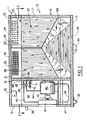
- the coolness storage air conditioner appliance of the invention includes a box-like thermally insulated housing 10 comprising a lid portion 11 and a body portion 12 hinged together at 13.
- the housing 10 is of narrow lateral width relative to its height and longitudinal length. It includes a floor 14, a front panel 15, a rear panel 16, an outer end panel 17, an inner end panel 18 and a top panel 19.
- a vertical lateral bulkhead 20 shown in section in Figures 1 and 5 divides the upper lid portion 11 of the housing 10 into an upper inlet manifold 21 and upper outlet manifold 22.
- a warm air inlet port 23 is provided in the rear panel 16 to communicate with the upper inlet manifold 21.
- a cool air outlet port 24 is formed in the front panel 15 of the housing 10 to communicate with the upper outlet manifold 22.
- An electric blower 26 is included in the upper outlet manifold 22 to force air out of the outlet port 25 and, as will be described hereafter, thereby draw air in through the upper inlet port 23.
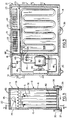
- the floor and top panels 14 and 19 and the front and back panels 15 and 16 of the housing 10 extend beyond the inner end panel 18 to the left as shown in Figures 1, 2 and 5 to provide a refrigeration compartment 30.
- the appliance of the invention is provided with wheels 35 and 36 located beneath the centre of gravity of the housing 10.
- Skid members 37 and 38 are also provided on the floor panel 14 beneath the outer end of the refrigeration compartment 30 remote from the wheels 35 and 36.
- a handle 39 is included on the exterior of the wall member 31 above the skid members 37 and 38.
- a conventional compressor 40 Within the refrigeration compartment 30 is a conventional compressor 40, fan motor 41, fan 42 and condenser coil 43 of a domestic-size refrigeration system.
- the system also includes a conventional refrigerant return tube 44 leading into the compressor 40, a refrigerant outlet tube 45 leading from the condenser coil 43, and an interconnecting tube 46 for directing hot discharge gas to the condenser coil 43 from the compressor 40.
- the interconnecting tube 46 passes in loops through an evaporation tray 47 which receives condensate during the cooling cycle of the appliance. The condesate is evaporated back to ambient air during the refrigerating cycle in a manner conventional to domestic refrigerators.
- the tray 47 also has the capacity to receive water leakage from one of the water chambers of the appliance which are described hereinafter.
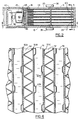
- the wall members are closely spaced parallel to one another and preferably are of sheet metal. They extend the length of the housing 10 beneath the upper inlet and outlet manifolds 21 and 22. They define six water chambers 51 alternating with seven air passageways 52, an adjoining pair of which are identified in Figure 4. Typical dimensions for the water chambers 51 are a thickness of 25.4 mm (one inch), a height of 610 mm (twenty-four inches) and a width of 762 mm (thirty inches) each holding 12.5 litres (3.3 gallons) of water. Each water chamber is also enclosed at the top but includes an upper opening with a fill cap 53 as shown in Figures 1, 2 and 5.
- each of the air passageways 52 extend downwardly between every other pair of wall members as extensions of the lateral bulkhead 20, thus dividing each of the air passageways 52 into two sections.
- One is a downflow section 56 from the inlet manifold 21 and the other is an up-flow section 57 to the outlet manifold 22.
- These down-flow and up-flow sections 56 and 57 are connected by a lower longitudinal cross flow section 58.
- vanes 59 in the form of corrugations 60 as shown in Figure 3 are provided for directing flow of air from the down-flow section 56 across to the up-flow section 57.
- Corrugated dividers 61 are provided in each of the respective seven air passageways 52 as shown in Figure 4 to support the associated wall members 50A and 50B while permitting air flow.
- the refrigerant tube 45 enters a lateral inlet header 65 from which twelve feeder tubes 66 extend through the inner end panel 18 to respective evaporator conduits 67 disposed in a series of six pairs of closed loops as shown in Figure 5, one pair for each respective water chamber 51.
- Each of the wall members 50A, B and C is of double thickness, which is to say of metal laminations, preferably of steel, which are substantially though not entirely in full surface-to-surface welded contact with one another.
- metal laminations preferably of steel
- one evaporator conduit 67A is within the wall member 50B and another evaporator conduits 67B is within the wall member 50C, with their loops vertically offset from one another.
- the evaporator conduits 67 are therefore in close surface-to-surface heat transfer contact with water in the water chambers 51.
- Each of the twelve conduits 67 has an outlet tube 68 which carries the refrigerant back to a lateral outlet header 69 shown particularly in Figures 1, 2 and 5. From the outlet header 69 the tube 44 carries the refrigerant back to the compressor 40.
- Thermostatically operated switches 70 and 71 shown schematically in Figures 1 and 5 are adapted automatically to turn on the refrigeration system when water in the chambers 51 is fully melted and cease its operation when water in the chambers 51 is fully frozen.
- the appliance of the invention is portable.
- the total apparatus weighs approximately 345 lbs. However this weight is centered over the wheels 35 and 36 which permits movement of the appliance by hand.
- the appliance is intended to be shipped dry and the chambers 51 are to be filled with water by the user. This is easily done by lifting the hinged lid portion 11 of the housing 10, removing the fill caps 53 and filling the six chambers 51 almost but not quite to the top, leaving some air space for expansion during freezing.
- Being portable the appliance may be moved about a house from kitchen to living area to bedroom as required.
- the refrigeration system is shut down and only the blower is powered.
- Control panel means indicated schematically as 75 in Figure 1 then permits a high cooling setting on one half ton or 1.75 KW (6,000 Btu's/hr) for about 5 hours or a low cooling setting of one-third ton or 1.17 KW (4,000 Btu's/hr) for about 8 hours.
- the blower When operated in the charging cycle the blower is shut off and the refrigeration system quietly chills the refrigerant over a protracted period to progressively freeze the water in the chambers 51 to ice.
- the heat output of the refrigeration system in the charging cycle is comparable to that of a domestic refrigerator and therefore can discharge its heat during the charging cycle into the room to be later cooled. In contrast the heat discharge of a conventional room air conditioner is vastly greater and requires window mounting with exhaust to the outside of the building.
- the appliance of the invention is not window mounted there is no problem of security, corrosion, excess dirt, seasonal removal and reinstallation, blockage of view, outdoor air leakage, fitting to the window, short life, etc.
- the compressor 40 of the small refrigeration system of the appliance permits use with conventional 110 volt power.
- water in the chambers 51 can be frozen during protracted charging cycles and melted during brief cooling cycles to cool an interior air space.
- the user may correlate these cycles to low-cost off-peak periods and high-cost high-load periods.
- the blower 26 quietly draws air through the inlet port 23 and down the inlet section 56 of the air passageways 52, through the cross-flow section 58 and then up the outlet section 57 to the outlet manifold 22 and the outlet port 24. This causes the circulating air to be thoroughly chilled by passing in close heat exchange contact with the wall members 50A and 50B which in turn have been chilled by the frozen ice in the various water chambers 51.
- the refrigeration system automatically commences operation to send chilled refrigerant through the evaporator conduits 66 which are also in close surface-to-surface heat exchange contact with the chambers 51, thus freezing the water.
- the operation of the appliance of the invention can be partly automatic, switching the cooling cycle to the charging cycle when the water in the chambers 51 is fully melted.
- the operator may selectively switch back from the charging cycle to the cooling cycle as needed.
- the evaporator conduits may be tubes mounted within the double thickness wall members or mounted against the water chamber side of single thickness wall members.
- the evaporator conduits may be centralized within the respective water chambers and held in place by appropriate spacers, in which case a single evaporator tube would suffice for each water chamber, a total of six rather than twelve.
- the water chambers may also be formed as blow-molded plastic containers providing their own wall members for defining the air passageways, or be formed as flexible plastic bags supported by separate wall members.
- Cross bracing spacers may be provided within each water chamber to prevent crushing of the wall members defining a still-empty water chamber when that next to it is filled with water.
Landscapes
- Engineering & Computer Science (AREA)
- Mechanical Engineering (AREA)
- General Engineering & Computer Science (AREA)
- Chemical & Material Sciences (AREA)
- Combustion & Propulsion (AREA)
- Life Sciences & Earth Sciences (AREA)
- Sustainable Development (AREA)
- Physics & Mathematics (AREA)
- Thermal Sciences (AREA)
- Devices That Are Associated With Refrigeration Equipment (AREA)
- Other Air-Conditioning Systems (AREA)
- Air-Conditioning Room Units, And Self-Contained Units In General (AREA)
Claims (10)
- Appareil de conditionnement d'air à accumulation de froid pour refroidir un espace d'air intérieur comprenant :(a) un coffre (10), thermiquement isolé, en forme de boîte, d'une largeur transversale relativement étroite par rapport à sa hauteur et à sa longueur longitudinale ;(b) un certain nombre d'éléments parois (50), étroitement rapprochés, conducteurs de la chaleur, définissant, dans le coffre, des chambres à eau (51) et des passages d'air (52) ;(c) les chambres à eau (51) étant conçues pour contenir de l'eau en contact de transfert de chaleur avec les éléments parois (50) associés ;(d) des moyens formant conduits évaporateurs (67) conçus pour être en contact de transfert de chaleur avec l'eau dans les chambres à eau (51) associées ;(e) un moyen de circulation pour déplacer de l'air dans lesdits passages (52) à partir dudit espace d'air intérieur et vers celui-ci ; et(f) des moyens de réfrigération du type compresseur-condenseur (30) d'une capacité de réfrigération limitée permettant l'évacuation de la chaleur directement dans ledit espace d'air intérieur et conçus pour faire circuler un réfrigérant dans lesdits moyens formant conduits (67) ;(g) ce par quoi l'eau dans lesdites chambres (51) peut être gelée pendant des cycles de charge prolongés et fondue pendant des cycles de refroidissement brefs pour refroidir ledit espace inférieur ; caractérisé par :(h) une cloison de séparation verticale (20) divisant le coffre en des collecteurs supérieurs d'entrée et de sortie (21, 22), des déflecteurs transversaux verticaux (55) s'étendant vers le bas à partir de la cloison de séparation (20) et divisant chaque passage d'air (52) en une section aval (56) par rapport au collecteur d'entrée (21) et une section amont (57) par rapport au collecteur de sortie (22), raccordées par une section longitudinale inférieure d'écoulement transversal (58).
- Appareil de conditionnement d'air selon la revendication 1, dans lequel des orifices d'entrée et de sortie (23, 24) sont prévus dans le coffre (10) mettant en communication les collecteurs supérieurs d'entrée (21) et de sortie (22) respectifs avec l'espace d'air intérieur.
- Appareil de conditionnement d'air selon la revendication 1 ou la revendication 2, dans lequel les éléments parois (50) sont verticaux et sont, parallèlement, étroitement rapprochés les uns des autres et définissent des chambres à eau (51) et des passages d'air (52) alternés.
- Appareil de conditionnement d'air selon l'une quelconque des revendications précédentes, dans lequel des ailettes (59) sont placées dans la section d'écoulement transversal (58) pour diriger l'écoulement d'air.
- Appareil de conditionnement d'air selon l'une quelconque des revendications 1 à 4, dans lequel des moyens écarteurs (61) sont inclus dans chacun des passages d'air (52) pour supporter les éléments parois (50) tout en permettant l'écoulement d'air.
- Appareil de conditionnement d'air selon l'une quelconque des revendications 1 à 5, qui comprend des moyens de commutation (70, 71) mis en oeuvre de manière thermostatique, conçus pour mettre en oeuvre automatiquement les moyens de réfrigération (30) lorsque l'eau dans lesdites chambres (51) est totalement fondue et pour mettre fin au fonctionnement desdits moyens de réfrigération (30) lorsque l'eau dans lesdites chambres (51) est totalement gelée.
- Appareil de conditionnement d'air selon l'une quelconque des revendications 1 à 6, dans lequel les moyens formant conduits évaporateurs (67) sont disposés en une série de boucles fermées à l'intérieur des éléments parois (50) associées.
- Appareil de conditionnement d'air selon la revendication 7, dans lequel les éléments parois (50) sont de forme feuilletée, les moyens formant conduits (67) étant définis entre leurs feuilles.
- Appareil de conditionnement d'air selon l'une quelconque des revendications 1 à 8, dans lequel le moyen de circulation est une soufflante (26).
- Appareil de conditionnement d'air selon l'une quelconque des revendications précédentes, incluant des moyens formant bouchons de remplissage (53) associés à chaque chambre à eau (51) permettant que les chambres à eau (51) soient remplies ou vidées d'eau de manière sélective de telle façon que l'appareil soit mobile et puisse être transporté les chambres à eau (51) étant vides.
Applications Claiming Priority (2)
| Application Number | Priority Date | Filing Date | Title |
|---|---|---|---|
| US07/476,257 US5005368A (en) | 1990-02-07 | 1990-02-07 | Coolness storage air conditioner appliance |
| US476257 | 1995-06-07 |
Publications (3)
| Publication Number | Publication Date |
|---|---|
| EP0441553A2 EP0441553A2 (fr) | 1991-08-14 |
| EP0441553A3 EP0441553A3 (en) | 1992-05-06 |
| EP0441553B1 true EP0441553B1 (fr) | 1995-01-04 |
Family
ID=23891128
Family Applications (1)
| Application Number | Title | Priority Date | Filing Date |
|---|---|---|---|
| EP91300854A Expired - Lifetime EP0441553B1 (fr) | 1990-02-07 | 1991-02-01 | Dispositif de conditionnement d'air avec accumulateur de froid |
Country Status (8)
| Country | Link |
|---|---|
| US (1) | US5005368A (fr) |
| EP (1) | EP0441553B1 (fr) |
| JP (1) | JPH06129664A (fr) |
| KR (1) | KR910021565A (fr) |
| BR (1) | BR9100383A (fr) |
| DE (1) | DE69106399T2 (fr) |
| ES (1) | ES2067144T3 (fr) |
| IL (1) | IL96993A (fr) |
Families Citing this family (32)
| Publication number | Priority date | Publication date | Assignee | Title |
|---|---|---|---|---|
| FR2689622B1 (fr) * | 1992-03-30 | 2001-04-13 | Carrier Sa | Faisceaux tubulaires d'échange thermique et bac de production et de stockage de glace comportant au moins un tel faisceau. |
| FR2689219A1 (fr) * | 1992-03-30 | 1993-10-01 | Carrier Sa | Dispositif de réfrigération de fluide; son application au traitement de l'air; bac de production et de stockage de glace et faisceau tubulaire d'échange thermique propre à faire partie d'un tel dispositif. |
| US5944089A (en) * | 1994-05-26 | 1999-08-31 | Roland; Russel Anthony | Thermal storage systems for buildings |
| JP4174929B2 (ja) * | 1998-10-23 | 2008-11-05 | 株式会社デンソー | 車両用空調装置 |
| US6427476B1 (en) * | 1999-08-26 | 2002-08-06 | Garey L. Eddins | Portable air conditioner |
| FR2800156A1 (fr) * | 1999-10-21 | 2001-04-27 | Raymond Chaillard | Appareil individuel mobile pour le rafraichissement de l'air d'un local |
| US8234876B2 (en) | 2003-10-15 | 2012-08-07 | Ice Energy, Inc. | Utility managed virtual power plant utilizing aggregated thermal energy storage |
| WO2005038366A1 (fr) * | 2003-10-15 | 2005-04-28 | Ice Energy, Inc | Appareil de refrigeration |
| DE602004009466T2 (de) * | 2003-10-15 | 2008-07-24 | Ice Energy, Inc., Fort Collins | Auf energiespeicherung basierendes hochleistungskältemittel und kühlsystem |
| US7854129B2 (en) * | 2003-10-15 | 2010-12-21 | Ice Energy, Inc. | Refrigeration apparatus |
| JP4864876B2 (ja) * | 2004-04-22 | 2012-02-01 | アイス エナジー インコーポレーテッド | 冷媒の圧力および流量を調節するための閉鎖システムならびに冷媒の圧力および流量を制御する方法 |
| MXPA06013529A (es) * | 2004-05-25 | 2007-08-21 | Ice Energy Inc | Sistema de enfriamiento y almacenamiento de energia termica basado en refrigerante con capacidad mejorada de intercambio de calor. |
| US6988371B2 (en) * | 2004-05-25 | 2006-01-24 | General Motors Corporation | Automotive HVAC system and method of operating same utilizing evaporator freezing |
| US7363772B2 (en) * | 2004-08-18 | 2008-04-29 | Ice Energy, Inc. | Thermal energy storage and cooling system with secondary refrigerant isolation |
| US7421846B2 (en) * | 2004-08-18 | 2008-09-09 | Ice Energy, Inc. | Thermal energy storage and cooling system with gravity fed secondary refrigerant isolation |
| US20110278307A1 (en) * | 2006-10-23 | 2011-11-17 | Ralph Muscatell | Water tank for use with a solar air conditioning system |
| KR100856030B1 (ko) * | 2007-11-12 | 2008-09-03 | 황길성 | 축냉동 에너지를 이용한 에어컨 |
| JP2011512508A (ja) * | 2008-02-15 | 2011-04-21 | アイス エナジー インコーポレーテッド | 共通の蒸発器コイルと伴に複数の冷媒および冷却ループを用いた熱エネルギ蓄積および冷却システム |
| US7980293B2 (en) * | 2008-03-21 | 2011-07-19 | Honeywell International Inc. | Two fluid thermal storage device to allow for independent heating and cooling |
| US20090293507A1 (en) * | 2008-05-28 | 2009-12-03 | Ice Energy, Inc. | Thermal energy storage and cooling system with isolated evaporator coil |
| USD602859S1 (en) * | 2008-10-30 | 2009-10-27 | Ice Energy, Inc. | Thermal energy storage module |
| USD629878S1 (en) | 2009-01-23 | 2010-12-28 | Ice Energy, Inc. | Air conditioner with integrated thermal energy storage |
| JP5408017B2 (ja) | 2009-06-05 | 2014-02-05 | 株式会社デンソー | 蓄冷熱交換器 |
| WO2012162646A1 (fr) | 2011-05-26 | 2012-11-29 | Ice Energy, Inc. | Système et procédé pour améliorer l'efficacité de réseau à l'aide d'une régulation de distribution statistique |
| JP2014520244A (ja) | 2011-06-17 | 2014-08-21 | アイス エナジー テクノロジーズ インコーポレーテッド | 液体−吸入の熱交換による熱エネルギー貯蔵のためのシステム及び方法 |
| NL2009052C2 (en) * | 2012-06-21 | 2013-12-24 | Autarkis B V | A container for pcm, a pcm unit, a pcm module comprising a series of pcm units, and a climate system comprising a pcm module. |
| KR20160053602A (ko) * | 2014-11-05 | 2016-05-13 | 현대자동차주식회사 | 잠열저장 모듈 및 잠열저장 장치 |
| JP6504972B2 (ja) * | 2015-08-20 | 2019-04-24 | 伊藤 彰 | 冷暖風送風機 |
| KR102034629B1 (ko) * | 2018-01-11 | 2019-11-08 | 엘지전자 주식회사 | 이동식 실내 유닛 및 이를 포함하는 공기조화 시스템 |
| US10830475B2 (en) | 2018-10-29 | 2020-11-10 | Johnson Controls Technology Company | Systems and methods for thermal storage in a zoning system |
| SE544812C2 (en) * | 2020-01-23 | 2022-11-29 | Locus Bonum Ab | A method for cooling of a user space and air conditioning arrangement |
| US20230174240A1 (en) * | 2021-12-06 | 2023-06-08 | Nostromo Ltd. | Mobile thermal energy storage |
Family Cites Families (7)
| Publication number | Priority date | Publication date | Assignee | Title |
|---|---|---|---|---|
| US2107088A (en) * | 1935-02-04 | 1938-02-01 | Leslie E Scott | Refrigerating apparatus |
| US2160760A (en) * | 1935-12-21 | 1939-05-30 | Mills Novelty Co | Refrigerating apparatus for vending machines and the like |
| US2436389A (en) * | 1945-09-04 | 1948-02-24 | Dole Refrigerating Co | Refrigerating plate and internal reinforcement therefor |
| DE1966859A1 (de) * | 1968-09-09 | 1974-11-21 | Thermo Bauelement Ag | Luftkuehlgeraet |
| AT371241B (de) * | 1976-09-24 | 1983-06-10 | Laing Nikolaus | Vorrichtung zur nutzung der solarenergie |
| NL168929C (nl) * | 1978-03-23 | 1982-05-17 | Stichting Bouwcentrum | Zonnewarmte-inrichting en warmteaccumulatie-middelen ten gebruike daarin. |
| US4403644A (en) * | 1982-09-20 | 1983-09-13 | Hebert Raymond T | Method and apparatus for room temperature stabilization |
-
1990
- 1990-02-07 US US07/476,257 patent/US5005368A/en not_active Expired - Fee Related
-
1991
- 1991-01-22 IL IL9699391A patent/IL96993A/en not_active IP Right Cessation
- 1991-01-24 BR BR919100383A patent/BR9100383A/pt not_active IP Right Cessation
- 1991-01-29 KR KR1019910001521A patent/KR910021565A/ko not_active Withdrawn
- 1991-02-01 DE DE69106399T patent/DE69106399T2/de not_active Expired - Fee Related
- 1991-02-01 EP EP91300854A patent/EP0441553B1/fr not_active Expired - Lifetime
- 1991-02-01 ES ES91300854T patent/ES2067144T3/es not_active Expired - Lifetime
- 1991-02-04 JP JP3035638A patent/JPH06129664A/ja active Pending
Also Published As
| Publication number | Publication date |
|---|---|
| IL96993A0 (en) | 1992-03-29 |
| BR9100383A (pt) | 1991-10-22 |
| EP0441553A3 (en) | 1992-05-06 |
| DE69106399D1 (de) | 1995-02-16 |
| DE69106399T2 (de) | 1996-05-23 |
| EP0441553A2 (fr) | 1991-08-14 |
| IL96993A (en) | 1994-10-21 |
| JPH06129664A (ja) | 1994-05-13 |
| ES2067144T3 (es) | 1995-03-16 |
| US5005368A (en) | 1991-04-09 |
| KR910021565A (ko) | 1991-12-20 |
Similar Documents
| Publication | Publication Date | Title |
|---|---|---|
| EP0441553B1 (fr) | Dispositif de conditionnement d'air avec accumulateur de froid | |
| US4776182A (en) | Circulating air refrigerator and power module for same | |
| US6467298B2 (en) | Energy transfer systems for refrigerator/freezer components | |
| US5220807A (en) | Combined refrigerator water heater | |
| US8161760B2 (en) | Utilities grid for distributed refrigeration system | |
| US5743109A (en) | Energy efficient domestic refrigeration system | |
| US8336322B2 (en) | Distributed refrigeration system with optional storage module and controller | |
| US8061153B2 (en) | Refrigeration appliance with optional storage module | |
| EP2026021A2 (fr) | Système de cascade thermique pour système de réfrigération domestique distribué | |
| EP2009374A2 (fr) | Système de réfrigération distribué avec modules de stockage personnalisés | |
| EP2009372A2 (fr) | Modules de stockage de réfrigérateur temporaire | |
| MX2007015310A (es) | Sistema de refrigeracion modular de capacidad variable para cocinas. | |
| US20120174607A1 (en) | Refrigeration appliance with optional storage module | |
| US5666817A (en) | Energy transfer system for refrigerator/freezer components | |
| WO2020253252A1 (fr) | Machine de climatisation tout-en-un pour cuisine | |
| EP0954732A1 (fr) | Systeme de transfert d'energie destine a des composants de refrigerateur-congelateur | |
| JP2657100B2 (ja) | 冷却装置 | |
| JPH03267664A (ja) | 夜間電力利用の冷房給湯装置 | |
| CN213273359U (zh) | 一种保鲜库 | |
| KR101195282B1 (ko) | 일체형 열교환기의 단열 패널 | |
| JP2685599B2 (ja) | 蓄熱式冷却装置 | |
| JP2000337750A (ja) | 冷蔵庫 | |
| JPH063338B2 (ja) | 冷凍・冷蔵オープンショーケースを備えた店舗構造 | |
| CA1293618C (fr) | Dispositif refrigerateur et son module de puissance pour l'air en circulation | |
| CN113266966A (zh) | 热泵两联供水系统 |
Legal Events
| Date | Code | Title | Description |
|---|---|---|---|
| PUAI | Public reference made under article 153(3) epc to a published international application that has entered the european phase |
Free format text: ORIGINAL CODE: 0009012 |
|
| AK | Designated contracting states |
Kind code of ref document: A2 Designated state(s): BE DE ES FR GB GR IT |
|
| PUAL | Search report despatched |
Free format text: ORIGINAL CODE: 0009013 |
|
| AK | Designated contracting states |
Kind code of ref document: A3 Designated state(s): BE DE ES FR GB GR IT |
|
| 17P | Request for examination filed |
Effective date: 19921013 |
|
| 17Q | First examination report despatched |
Effective date: 19931011 |
|
| GRAA | (expected) grant |
Free format text: ORIGINAL CODE: 0009210 |
|
| AK | Designated contracting states |
Kind code of ref document: B1 Designated state(s): BE DE ES FR GB GR IT |
|
| ITF | It: translation for a ep patent filed | ||
| PGFP | Annual fee paid to national office [announced via postgrant information from national office to epo] |
Ref country code: GB Payment date: 19950131 Year of fee payment: 5 |
|
| REF | Corresponds to: |
Ref document number: 69106399 Country of ref document: DE Date of ref document: 19950216 |
|
| PGFP | Annual fee paid to national office [announced via postgrant information from national office to epo] |
Ref country code: ES Payment date: 19950306 Year of fee payment: 5 |
|
| PGFP | Annual fee paid to national office [announced via postgrant information from national office to epo] |
Ref country code: FR Payment date: 19950309 Year of fee payment: 5 |
|
| REG | Reference to a national code |
Ref country code: ES Ref legal event code: FG2A Ref document number: 2067144 Country of ref document: ES Kind code of ref document: T3 |
|
| PGFP | Annual fee paid to national office [announced via postgrant information from national office to epo] |
Ref country code: DE Payment date: 19950322 Year of fee payment: 5 |
|
| ET | Fr: translation filed | ||
| PGFP | Annual fee paid to national office [announced via postgrant information from national office to epo] |
Ref country code: BE Payment date: 19950330 Year of fee payment: 5 |
|
| PGFP | Annual fee paid to national office [announced via postgrant information from national office to epo] |
Ref country code: GR Payment date: 19950331 Year of fee payment: 5 |
|
| REG | Reference to a national code |
Ref country code: GR Ref legal event code: FG4A Free format text: 3014641 |
|
| PLBE | No opposition filed within time limit |
Free format text: ORIGINAL CODE: 0009261 |
|
| STAA | Information on the status of an ep patent application or granted ep patent |
Free format text: STATUS: NO OPPOSITION FILED WITHIN TIME LIMIT |
|
| 26N | No opposition filed | ||
| PG25 | Lapsed in a contracting state [announced via postgrant information from national office to epo] |
Ref country code: GB Effective date: 19960201 |
|
| PG25 | Lapsed in a contracting state [announced via postgrant information from national office to epo] |
Ref country code: ES Free format text: LAPSE BECAUSE OF NON-PAYMENT OF DUE FEES Effective date: 19960202 |
|
| PG25 | Lapsed in a contracting state [announced via postgrant information from national office to epo] |
Ref country code: BE Effective date: 19960228 |
|
| BERE | Be: lapsed |
Owner name: CALMAC MFG CORP. Effective date: 19960228 |
|
| PG25 | Lapsed in a contracting state [announced via postgrant information from national office to epo] |
Ref country code: GR Free format text: THE PATENT HAS BEEN ANNULLED BY A DECISION OF A NATIONAL AUTHORITY Effective date: 19960831 |
|
| GBPC | Gb: european patent ceased through non-payment of renewal fee |
Effective date: 19960201 |
|
| PG25 | Lapsed in a contracting state [announced via postgrant information from national office to epo] |
Ref country code: FR Effective date: 19961031 |
|
| REG | Reference to a national code |
Ref country code: GR Ref legal event code: MM2A Free format text: 3014641 |
|
| PG25 | Lapsed in a contracting state [announced via postgrant information from national office to epo] |
Ref country code: DE Effective date: 19961101 |
|
| REG | Reference to a national code |
Ref country code: FR Ref legal event code: ST |
|
| REG | Reference to a national code |
Ref country code: ES Ref legal event code: FD2A Effective date: 19990405 |
|
| PG25 | Lapsed in a contracting state [announced via postgrant information from national office to epo] |
Ref country code: IT Free format text: LAPSE BECAUSE OF NON-PAYMENT OF DUE FEES;WARNING: LAPSES OF ITALIAN PATENTS WITH EFFECTIVE DATE BEFORE 2007 MAY HAVE OCCURRED AT ANY TIME BEFORE 2007. THE CORRECT EFFECTIVE DATE MAY BE DIFFERENT FROM THE ONE RECORDED. Effective date: 20050201 |