EP0441555A2 - System for the detection of objects - Google Patents
System for the detection of objects Download PDFInfo
- Publication number
- EP0441555A2 EP0441555A2 EP91300858A EP91300858A EP0441555A2 EP 0441555 A2 EP0441555 A2 EP 0441555A2 EP 91300858 A EP91300858 A EP 91300858A EP 91300858 A EP91300858 A EP 91300858A EP 0441555 A2 EP0441555 A2 EP 0441555A2
- Authority
- EP
- European Patent Office
- Prior art keywords
- optical energy
- receiver
- port
- transmitter
- overlap
- Prior art date
- Legal status (The legal status is an assumption and is not a legal conclusion. Google has not performed a legal analysis and makes no representation as to the accuracy of the status listed.)
- Withdrawn
Links
Images


Classifications
-
- G—PHYSICS
- G01—MEASURING; TESTING
- G01S—RADIO DIRECTION-FINDING; RADIO NAVIGATION; DETERMINING DISTANCE OR VELOCITY BY USE OF RADIO WAVES; LOCATING OR PRESENCE-DETECTING BY USE OF THE REFLECTION OR RERADIATION OF RADIO WAVES; ANALOGOUS ARRANGEMENTS USING OTHER WAVES
- G01S17/00—Systems using the reflection or reradiation of electromagnetic waves other than radio waves, e.g. lidar systems
- G01S17/02—Systems using the reflection of electromagnetic waves other than radio waves
- G01S17/04—Systems determining the presence of a target
-
- G—PHYSICS
- G01—MEASURING; TESTING
- G01S—RADIO DIRECTION-FINDING; RADIO NAVIGATION; DETERMINING DISTANCE OR VELOCITY BY USE OF RADIO WAVES; LOCATING OR PRESENCE-DETECTING BY USE OF THE REFLECTION OR RERADIATION OF RADIO WAVES; ANALOGOUS ARRANGEMENTS USING OTHER WAVES
- G01S17/00—Systems using the reflection or reradiation of electromagnetic waves other than radio waves, e.g. lidar systems
- G01S17/88—Lidar systems specially adapted for specific applications
- G01S17/93—Lidar systems specially adapted for specific applications for anti-collision purposes
- G01S17/931—Lidar systems specially adapted for specific applications for anti-collision purposes of land vehicles
-
- G—PHYSICS
- G01—MEASURING; TESTING
- G01S—RADIO DIRECTION-FINDING; RADIO NAVIGATION; DETERMINING DISTANCE OR VELOCITY BY USE OF RADIO WAVES; LOCATING OR PRESENCE-DETECTING BY USE OF THE REFLECTION OR RERADIATION OF RADIO WAVES; ANALOGOUS ARRANGEMENTS USING OTHER WAVES
- G01S7/00—Details of systems according to groups G01S13/00, G01S15/00, G01S17/00
- G01S7/48—Details of systems according to groups G01S13/00, G01S15/00, G01S17/00 of systems according to group G01S17/00
- G01S7/481—Constructional features, e.g. arrangements of optical elements
- G01S7/4818—Constructional features, e.g. arrangements of optical elements using optical fibres
Definitions
- This invention relates to object detection and particularly, though not exclusively, to the detection of objects in the vicinity of vehicles such as automobiles.
- the invention provides a system for the detection of objects comprising: a source of optical energy; a multiplicity of ports including at least a first port for transmitting optical energy to a first field of illumination, at least a second port for receiving optical energy from a first field of reception and at least a third port for predeterminedly transmitting optical energy to a second field of illumination or receiving optical energy from a second field of reception, the fields of illumination and reception overlapping to define at least a first area of overlap between one of the fields of illumination and one of the fields of reception and a second area of overlap between one of the fields of illumination and one of the fields of reception; a receiver for receiving optical energy and for producing a signal representative thereof; characterised by: transmission fiber optic coupling means coupling the source of optical energy to the or each port for transmitting optical energy; reception fiber optic coupling means coupling the receiver to the or each port for receiving optical energy; sequential activation means for predeterminedly sequentially activating the first port for transmitting optical energy and the third port if the third port is a port for transmitting
- the invention provides a system for the detection of objects comprising: a source of optical energy; a first transmitter port at a first transmitter location for transmitting optical energy to a first field of illumination; a second transmitter port at a second transmitter location spaced from the first transmitter location for transmitting optical energy to a second field of illumination; at least one receiver port embracing a field of reception having a first area of overlap with the first field of illumination and having a second area of overlap with the second field of illumination so as to receive optical energy transmitted from the first or second transmitter port and reflected by an object present in the first or second area of overlap; a receiver coupled to the at least one receiver port for producing a signal representative of the optical energy received thereat; characterised by: fiber optic coupling means coupling the source of optical energy to the first and second transmitter ports; means for sequentially activating the first and second transmitter ports; and processing means for processing the signal produced by the receiver to sequentially detect the presence of an object in the first or second area of overlap.
- the invention provides a system for the detection of objects comprising: a source of optical energy; at least one transmitter port coupled to the source of optical energy for transmitting optical energy to a field of illumination; a first receiver port located at a first location and embracing a first field of reception having a first area of overlap with the field of illumination so as to receive optical energy transmitted from the at least one transmitter port and reflected by an object present in the first area of overlap; a second receiver port located at a second location spaced from the first location and embracing a second field of reception having a second area of overlap with the field of illumination so as to receive optical energy transmitted by the at least one transmitter and reflected by an object present in the second area of overlap; a receiver for receiving optical energy and for producing a signal representative thereof; characterised by: fiber optic coupling means coupling the first and second receiver ports to the receiver; means for sequentially activating the first and second receiver ports; and processing means for processing the signal produced by the receiver to sequentially detect the presence of an object in the first or second area of overlap.
- the invention thus provides a simple, reliable object detection system which is of low cost, uses parts which are few in number and are from a mature technology base, and which is readily suited to implementation and conditions encountered in an automobile.
- an automobile 2 has an object detection system 4 for use when the automobile is reversing at slow speed to detect objects at close range.
- the object detection system 4 includes a single central transmitter light source 6 (which will be described in further detail below) and a transmission optical fiber 8.
- the transmission optical fiber 8 extends from the transmitter light source 6 and around the rear periphery of the automobile 2.
- the transmission optical fiber 8 is provided along its length at a number of spaced points (only two of which are shown) around the rear periphery of the automobile with output ports 10, 12 through which part of the light from the fiber emerges through apertures in a panel or bumper of the automobile 2.
- Each output port is formed by a short optical fiber joined to the transmission optical fiber 8 by a conventional optical splitter (not shown).
- a shutter 14 for switching off and on light emerging from the output port and a beam shaping lens 16 (e.g. a conventional spherical optical lens or a graded index of refraction (GRIN) lens) for focussing light emerging from the shutter into parallel beams covering predetermined fields of illumination 18, 20.
- a beam shaping lens 16 e.g. a conventional spherical optical lens or a graded index of refraction (GRIN) lens
- the object detection system 4 includes a single central light receiver 22 (which will be described in further detail below) and a reception optical fiber 24.
- the reception optical fiber 24 extends around the rear periphery of the automobile 2 and to the light receiver 22.
- the reception optical fiber 24 is provided along its length at a number of spaced points (only two of which are shown) around the rear periphery of the automobile with input ports 26, 28 through which exterior light is introduced into the fiber through apertures in the panel or bumper of the automobile 2.
- Each input port is formed by a short optical fiber joined to the reception optical fiber 24 by a conventional optical splitter/combiner, such as a fuzed-junction star coupler (not shown).
- a shutter 30 for switching off and on exterior light to the input port and a beam shaping lens 32 (e.g. a conventional spherical optical lens or a graded index of refraction (GRIN) lens) for focussing exterior light to the shutter from respective parallel beams covering predetermined fields of reception 34, 36.
- a beam shaping lens 32 e.g. a conventional spherical optical lens or a graded index of refraction (GRIN) lens
- the fields of illumination 18, 20 and the fields of reception 34, 36 are arranged to overlap so as to define four co-planar areas of overlap: (i) an area of overlap 38 between the field of illumination 18 and the field of reception 34, (ii) an area of overlap 40 between the field of illumination 18 and the field of reception 36, (iii) an area of overlap 42 between the field of illumination 20 and the field of reception 34, and (iv) an area of overlap 44 between the field of illumination 20 and the field of reception 36.
- the object detection system 4 further includes an electrical driver circuit 46 for driving the single central transmitter light source 6, an electrical receiver circuit 48, an electrical correlator circuit 50 for correlating signals from the optical receiver 20 with signals to the transmitter light source 6, and a signal processor 52 for generating activation and switching signals for the transmitter light source 6 and the transmission and reception shutters 14, 30 and for processing the correlated receiver signals to produce an output detection signal.
- an electrical driver circuit 46 for driving the single central transmitter light source 6, an electrical receiver circuit 48, an electrical correlator circuit 50 for correlating signals from the optical receiver 20 with signals to the transmitter light source 6, and a signal processor 52 for generating activation and switching signals for the transmitter light source 6 and the transmission and reception shutters 14, 30 and for processing the correlated receiver signals to produce an output detection signal.
- the single central optical transmitter 6 includes a housing 54 holding a light emitting diode (LED) 56 of the type sold under the part no. MFOE71 by Motorola, Inc., Semiconductor Products Sector, 3102 North 56th Street, Phoenix, Arizona 85018.
- the transmission optical fiber 8 (e.g. that sold under the part no. ESKA SH4001 by Mitsubishi International, Tokyo, Japan) is coupled to the LED 56 and is held in place by a screw-thread "cinch" connector 58 which fastens to the housing and through which the optical fiber 8 passes.
- Electrical inputs 60 of the LED 56 are connected to the transmitter driver circuit 46. It will be appreciated that, if desired, another kind of LED or other light source may alternatively be used, e.g. a semiconductor laser diode.
- the transmitter driver circuit 46 includes a voltage supply node 62 for coupling to a source of positive voltage supply V CC , a resistor 64 having one end connected to the voltage supply node 62 and having its other end connected to the LED 56, and a bipolar npn transistor 66.
- the transistor 66 which may be of the type sold under the part no. 2N2222 by Motorola, Inc. Semiconductor Products Sector, 3102 North 56th Street, Phoenix, Arizona 85018, has its emitter connected to ground and has its collector connected to the LED 56.
- a conventional square wave oscillator 68 controlled by the signal processor 52, is connected to the base of the transistor 64 via a conventional buffer 70.
- the single central optical receiver 22 includes a housing 72 holding a semiconductor light detector 74 of the type sold under the part no. MFOD72 by Motorola, Inc. Semiconductor Products Sector, 3102 North 56th Street, Phoenix, Arizona 85018.
- the reception optical fiber 24 (e.g. of the same part no. ESKA SH4001 as the transmission optical fiber 8) is coupled to the detector 74 and is held in place by a screw-thread "cinch" connector 76 which fastens to the housing and through which the optical fiber 24 passes.
- Electrical outputs 78 from the light detector 74 are connected to the electrical receiver circuit 48.
- the electrical receiver circuit 48 includes a voltage supply node 80 for coupling to the source of voltage supply V CC and a voltage supply node 82 for coupling to source of negative voltage supply -V CC .
- the voltage supply node 80 is connected to one side of the light detector 74, and a pnp transistor 84 has its emitter connected to another side of the light detector 74.
- the transistor 84 has its base connected to ground and has its collector connected to the voltage supply node 82 via a resistor 86.
- the collector of the transistor 84 is also connected via a capacitor 88 and a buffer amplifier 90 to the correlator circuit 50.
- the electrical receiver circuit 48 amplifies and buffers the electrical signal output from the light detector 74.
- the correlator circuit 50 includes a first input for receiving the output of the electrical receiver circuit 48, and a second input for receiving the activation signal applied to the transmitter driver circuit 46.
- the correlator circuit also includes a conventional mixer 92 for mixing the signals at the two inputs of the circuit.
- the mixer output is connected via a low-pass filter 94, an integrator 96 and a threshold detector 98 to the signal processor 52.
- the correlator circuit mixes together the light detector output signal with the transmitted signal, generating a mixed signal having a low-frequency component corresponding to those components of the light detector output signal and the transmitted signal which correlate.
- the correlator circuit filters out from the mixed signal any high frequency component(s) which correspond to those component(s) which may be present in the light detector output signal and which do not correlate with the transmitted signal.
- the shutters 14, 30 associated with each of the output and input ports 10, 12 and 26, 28 are implemented as mechanical shutters formed by a rotatable glass prism 100 located in the path of light to or from the output ports 10, 12 or input ports 34, 36 respectively.
- the prism In a first position as shown in FIG. 7(a), corresponding to the shutter being open, the prism is positioned with parallel faces 102, 104 each perpendicular to and intersecting with a light path 106, so that the light passes directly through the prism with substantially no reflection.
- a second position as shown in FIG.
- the prism is rotated through approximately 90° about an axis through its center 108 perpendicular to the plane of the drawing so that parallel faces 110, 112 intersect the light path 106 at an acute angle.
- the faces 110, 112 are coated with a reflective layer such as gold or aluminum so that substantially all of the light incident upon the prism is reflected with substantially no transmission.
- a reflective layer such as gold or aluminum
- F12-F-E-1 by DiCon Fiberoptics, Inc., 44140 Warm Springs Boulevard., Fremont, California 94539, in which an output optical fiber is moved into and out of alignment with an input optical fiber so as to be transmissive or non-transmissive to to an optical signal therefrom.
- FIG. 8 shows a flow chart illustrating the operation of the signal processor 52, in use of the object detection system 4 shown in FIG. 1, the system is enabled when the automobile begins reversing, e.g. when reverse gear is engaged.
- the signal processor 52 firstly activates the central transmitter light source 6, and simultaneously activates the transmission shutter 14 associated with the transmission output port 10 and also the reception shutter 30 associated with the reception input port 26. Light is thus transmitted from the output port 10 and illuminates the transmission field 18.
- any signal produced from the optical receiver 22 in response to this activation is buffered by the receiver circuit 48, correlated with the transmitter activation signal (so as to minimize errors in detection) by the correlator circuit 50, and processed by the signal processor 52 to produce an output detection signal which may be used to activate a warning signal (e.g.
- the signal processor 52 then de-activates the central transmitter light source 6, the transmission shutter 14 associated with the transmission output port 10 and the reception shutter 30 associated with the reception input port 26.
- the signal processor 52 secondly activates the central transmitter light source 6, and simultaneously activates the transmission shutter 14 associated with the transmission output port 10 and also the reception shutter 30 associated with the reception input port 28. Light is thus transmitted from the output port 10 and illuminates the transmission field 18. If there is an object in the area of overlap 40 between the transmission field 18 and the reception field 36, the object will cause light transmitted in the field 18 to be reflected in the field 36 and the reflected light will be introduced into the reception optical fiber 24 at the input port 28 and will be received at the central optical receiver 22. If no object is present in the area of overlap 40, no light will be reflected.
- Any signal produced from the optical receiver 22 in response to this activation is buffered by the receiver circuit 48, correlated with the transmitter activation signal by the correlator circuit 50, and processed by the signal processor 52 to produce an output detection signal which may be used in the ways described above.
- the signal processor 52 then de-activates the central transmitter light source 6, the transmission shutter 14 associated with the transmission output port 10 and the reception shutter 30 associated with the reception input port 28.
- the signal processor 52 thirdly activates the central transmitter light source 6, and simultaneously activates the transmission shutter 14 associated with the transmission output port 12 and also the reception shutter 30 associated with the reception input port 26. Light is thus transmitted from the output port 12 and illuminates the transmission field 20. If there is an object in the area of overlap 42 between the transmission field 20 and the reception field 34, the object will cause light transmitted in the field 20 to be reflected in the field 34 and the reflected light will be introduced into the reception optical fiber 24 at the input port 26 and will be received at the central optical receiver 22. If no object is present in the area of overlap 42, no light will be reflected.
- any signal produced from the optical receiver 22 in response to this activation is buffered by the receiver circuit 48, correlated with the transmitter activation signal by the correlator circuit 50, and processed by the signal processor 52 to produce an output detection signal which may be used in the ways described above.
- the signal processor 52 then de-activates the central transmitter light source 6, the transmission shutter 14 associated with the transmission output port 12 and the reception shutter 30 associated with the reception input port 26.
- the signal processor 52 fourthly activates the central transmitter light source 6, and simultaneously activates the transmission shutter 14 associated with the transmission output port 12 and also the reception shutter 30 associated with the reception input port 28. Light is thus transmitted from the output port 12 and illuminates the transmission field 20. If there is an object in the area of overlap 44 between the transmission field 20 and the reception field 36, the object will cause light transmitted in the field 20 to be reflected in the field 36 and the reflected light will be introduced into the reception optical fiber 24 at the input port 28 and will be received at the central optical receiver 22. If no object is present in the area of overlap 44, no light will be reflected.
- any signal produced from the optical receiver 22 in response to this activation is buffered by the receiver circuit 48, correlated with the transmitter activation signal by the correlator circuit 50, and processed by the signal processor 52 to produce an output detection signal which may be used in the ways described above.
- the signal processor 52 then de-activates the central transmitter light source 6, the transmission shutter 14 associated with the transmission output port 12 and the reception shutter 30 associated with the reception input port 28.
- the signal processor 52 then begins again the above described cycle of activation to detect objects present in the areas of overlap 38, 40, 42 and 44.
- the cycle is repeated continually until the automobile stops reversing, e.g. when reverse gear is disengaged.
- the signal processor 52 may be conveniently implemented in the form of a high-speed, integrated circuit digital signal processor to optimize system performance, size, power consumption and reliability.
- a range of such digital signal processors is available, and the choice and programming of a particular suitable digital signal processor to carry out the operation shown in the flow chart of FIG. 8 is fully within the ordinary competence of a person skilled in the art, and so will not be described further herein.
- the signal processor 52 may in future be implemented in the form of an optical processor.
- the central transmitter light source 6 need not be de-activated and re-activated with respective de-activations and re-activations of the shutters 12 and 30, but may instead be continuously activated while the system is in operation.
- the system may be activated when the car is stationary and in neutral gear or a forward gear, e.g. at a stop light, to warn the driver of other vehicles which may come close.
- light of any frequency may be used for transmission and reception in the system.
- the term “light” is used the term should not be construed as limiting the frequency used to the visible part of the spectrum; the "light” can be of any frequency (e.g. having a wavelength in the range 0.1 ⁇ m - 100 ⁇ m) that can be carried by an optical fiber.
- light of a lower frequency e.g. infra-red
- light of a higher frequency e.g. ultra-violet
- the object detection system described above affords high levels of design flexibility, and operational durability and reliability, since the light source 6 and the light receiver 22 (together with the associated electrical circuits 46, 48, 50 and 52) can be mounted inboard in the automobile at any desired location, free from harsh physical conditions, the optical fibers 8 and 24 coupling the inboard components to the peripheral ports in the fibers and their associated lenses and shutters.
- optical fibers could be of any inorganic or organic compounds which can be formed into an optical waveguide (e.g.plastic or glass) and could be easily bent to conform to the shape of the automobile body or bumper.
- optical waveguide e.g. plastic or glass
- an optical spectral filter may be employed to filter received light in the range to which the receiver 74 is responsive (e.g. in the wavelength range 0.8 ⁇ 0.05 ⁇ m).
- the spectral filters may be integrated into the material of the lenses 16, 32 (e.g. the lenses may be made of glass of the designation R6870 sold by Schott Glass Technologies, Inc., 400 York Avenue, Duryea, Pennsylvania 18642).
- the system could be expanded or adapted to cover any desired angle as required.
- the system could cover the sides and the complete front and rear bumpers.
- the system could also cover the underside of the automobile.
- the transmitter output ports and receiver input ports can be aligned in, or moved to cover, more than one plane if desired, so as to give optimal detection coverage for a particular application. For example for use at very close range it may be desired to move the transmitter output ports and receiver input ports so as to provide detection coverage very near to the ground. It will further be appreciated that, if desired, the pattern of detection coverage could be adapted to suit the speed and steering of the automobile.
- post-reception integration of the received signal may be performed in the signal processor 52 to reduce susceptibility of the system to spurious, short duration light signals.
- the transmitted optical signal could be modulated or coded as desired and the receiver circuitry could be arranged to respond only to received signals having the appropriate modulation or coding.
- an object detection system as described above offers the advantages of multiple fields of view with a single transmitter source and a single receiver detection circuit, low system cost since the system comprises few parts, and high reliability and simplicity of implementation since the system is simple and consists of parts from a mature technology base.
Landscapes
- Physics & Mathematics (AREA)
- Engineering & Computer Science (AREA)
- Electromagnetism (AREA)
- Computer Networks & Wireless Communication (AREA)
- General Physics & Mathematics (AREA)
- Radar, Positioning & Navigation (AREA)
- Remote Sensing (AREA)
- Optical Radar Systems And Details Thereof (AREA)
Abstract
A system (4) for use in an automobile (2) for the detection of objects comprising: a light source (6); a plurality of spaced transmitter ports (10, 12) for respectively transmitting light to a plurality of fields of illumination (18, 20); an optical fiber coupling the light source to the transmitter ports; a plurality of receiver ports (10, 12) embracing respectively a plurality of fields of reception (34, 36) each having an area of overlap (38, 40, 42, 44) with each of the plurality of fields of illumination so as to receive light transmitted from one of the transmitter ports and reflected by an object present in an area of overlap; a receiver (22) for receiving light and for producing a signal representative thereof; an optical fiber (24) coupling the receiver ports to the receiver; and processing means (52) for sequentially activating each of the transmitter ports with each of the receiver ports, and for processing the signal produced by the receiver in response to each activation to detect the presence of an object in each of the areas of overlap.
Description
- This invention relates to object detection and particularly, though not exclusively, to the detection of objects in the vicinity of vehicles such as automobiles.
- It has long been considered desirable in automobiles to be able automatically to detect nearby vehicles or other objects so as to enable appropriate avoiding action to be taken. It is known to use radar systems to detect nearby vehicles or other objects, and in particular it is known, for example from US patents nos. 4552456 and 4632543, to use an optical radar. However, the complexity and cost of existing radar systems have heretofor prevented their general incorporation in automobiles.
- From U.S. Patent No. 4,818,887 there is known an motor vehicle object detection system in which, normally, a first electromagnetic radiation transmitter is associated with a first detector and a second electromagnetic radiation transmitter is associated with a second detector, the first and second transmitter/detector pairs being operated alternately to unambiguously detect an object in the overlapping examination areas of the first and second transmitter/detector pairs. In an alternative operational mode, the first transmitter is associated with the second detector, and the second transmitter is associated with the first detector; this causes the examination areas of the associated pairs to be located at a considerably greater distance in front of the vehicle than normally, reducing the falsing effects of close-by water droplets. However, such a system requires two transmitters and two receivers.
- For the avoidance of doubt and for the purpose of clarification, it should be understood that as used herein the term "plurality" is intended to mean "two or more" and the term "multiplicity" is intended to mean "three or more".
- It is an object of the present invention to provide a new and improved system for the detection of objects wherein the above mentioned disadvantages may be overcome or at least alleviated.
- In one aspect the invention provides a system for the detection of objects comprising:
a source of optical energy;
a multiplicity of ports including at least a first port for transmitting optical energy to a first field of illumination, at least a second port for receiving optical energy from a first field of reception and at least a third port for predeterminedly transmitting optical energy to a second field of illumination or receiving optical energy from a second field of reception, the fields of illumination and reception overlapping to define at least a first area of overlap between one of the fields of illumination and one of the fields of reception and a second area of overlap between one of the fields of illumination and one of the fields of reception;
a receiver for receiving optical energy and for producing a signal representative thereof; characterised by:
transmission fiber optic coupling means coupling the source of optical energy to the or each port for transmitting optical energy;
reception fiber optic coupling means coupling the receiver to the or each port for receiving optical energy;
sequential activation means for predeterminedly sequentially activating the first port for transmitting optical energy and the third port if the third port is a port for transmitting optical energy, whereby to sequentially illuminate the first second fields of illumination from the source of optical energy, or sequentially activating the first port for receiving optical energy and the third port if the third port is a port for receiving optical energy, whereby to sequentially receive optical energy at the receiver from the first and second fields of reception; and
processing means for processing the signal produced by the receiver to sequentially detect the presence of an object in the first area of overlap or in the second area of overlap. - In a further asepct the invention provides a system for the detection of objects comprising:
a source of optical energy;
a first transmitter port at a first transmitter location for transmitting optical energy to a first field of illumination;
a second transmitter port at a second transmitter location spaced from the first transmitter location for transmitting optical energy to a second field of illumination;
at least one receiver port embracing a field of reception having a first area of overlap with the first field of illumination and having a second area of overlap with the second field of illumination so as to receive optical energy transmitted from the first or second transmitter port and reflected by an object present in the first or second area of overlap;
a receiver coupled to the at least one receiver port for producing a signal representative of the optical energy received thereat;
characterised by:
fiber optic coupling means coupling the source of optical energy to the first and second transmitter ports;
means for sequentially activating the first and second transmitter ports; and
processing means for processing the signal produced by the receiver to sequentially detect the presence of an object in the first or second area of overlap. - In a further aspect, the invention provides a system for the detection of objects comprising:
a source of optical energy;
at least one transmitter port coupled to the source of optical energy for transmitting optical energy to a field of illumination;
a first receiver port located at a first location and embracing a first field of reception having a first area of overlap with the field of illumination so as to receive optical energy transmitted from the at least one transmitter port and reflected by an object present in the first area of overlap;
a second receiver port located at a second location spaced from the first location and embracing a second field of reception having a second area of overlap with the field of illumination so as to receive optical energy transmitted by the at least one transmitter and reflected by an object present in the second area of overlap;
a receiver for receiving optical energy and for producing a signal representative thereof;
characterised by:
fiber optic coupling means coupling the first and second receiver ports to the receiver;
means for sequentially activating the first and second receiver ports; and
processing means for processing the signal produced by the receiver to sequentially detect the presence of an object in the first or second area of overlap. - In a preferred embodiment the invention thus provides a simple, reliable object detection system which is of low cost, uses parts which are few in number and are from a mature technology base, and which is readily suited to implementation and conditions encountered in an automobile.
- One system in accordance with the present invention for use in an automobile when reversing for the detection of objects will now be described, by way of example only, with reference to the accompanying drawings, in which:
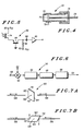
- FIG. 1 shows a schematic plan view of the rear of an automobile incorporating the system; and
- FIG.2 shows a cross-sectional diagram of an optical transmitter used in the system of FIG. 1;
- FIG.3 shows a part-schematic circuit diagram of an electrical transmitter circuit for driving the optical transmitter of FIG. 2;
- FIG.4 shows a cross-sectional diagram of an optical receiver used in the system of FIG. 1;
- FIG.5 shows a circuit diagram of an electrical receiver circuit for use with the optical receiver of FIG. 4;
- FIG.6 shows a block-schematic circuit diagram of a correlator used in the system of FIG. 1;
- FIGS. 7(a) and 7(b) show different modes of operation of a shutter mechanism used in the system of FIG. 1; and
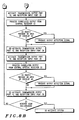
- FIG. 8 shows a flow chart illustrating operation of a signal processor of the system.
- Referring now to FIG. 1, an
automobile 2 has an object detection system 4 for use when the automobile is reversing at slow speed to detect objects at close range. The object detection system 4 includes a single central transmitter light source 6 (which will be described in further detail below) and a transmissionoptical fiber 8. The transmissionoptical fiber 8 extends from thetransmitter light source 6 and around the rear periphery of theautomobile 2. The transmissionoptical fiber 8 is provided along its length at a number of spaced points (only two of which are shown) around the rear periphery of the automobile withoutput ports automobile 2. Each output port is formed by a short optical fiber joined to the transmissionoptical fiber 8 by a conventional optical splitter (not shown). At eachoutput port illumination - The object detection system 4 includes a single central light receiver 22 (which will be described in further detail below) and a reception
optical fiber 24. The receptionoptical fiber 24 extends around the rear periphery of theautomobile 2 and to thelight receiver 22. The receptionoptical fiber 24 is provided along its length at a number of spaced points (only two of which are shown) around the rear periphery of the automobile withinput ports automobile 2. Each input port is formed by a short optical fiber joined to the receptionoptical fiber 24 by a conventional optical splitter/combiner, such as a fuzed-junction star coupler (not shown). At eachinput port reception - The fields of
illumination reception overlap 38 between the field ofillumination 18 and the field ofreception 34, (ii) an area ofoverlap 40 between the field ofillumination 18 and the field ofreception 36, (iii) an area ofoverlap 42 between the field ofillumination 20 and the field ofreception 34, and (iv) an area of overlap 44 between the field ofillumination 20 and the field ofreception 36. - The object detection system 4 further includes an
electrical driver circuit 46 for driving the single centraltransmitter light source 6, anelectrical receiver circuit 48, anelectrical correlator circuit 50 for correlating signals from theoptical receiver 20 with signals to thetransmitter light source 6, and asignal processor 52 for generating activation and switching signals for thetransmitter light source 6 and the transmission andreception shutters - Referring now to FIG. 2, in a preferred embodiment of the present invention the single central
optical transmitter 6 includes ahousing 54 holding a light emitting diode (LED) 56 of the type sold under the part no. MFOE71 by Motorola, Inc., Semiconductor Products Sector, 3102 North 56th Street, Phoenix, Arizona 85018. The transmission optical fiber 8 (e.g. that sold under the part no. ESKA SH4001 by Mitsubishi International, Tokyo, Japan) is coupled to theLED 56 and is held in place by a screw-thread "cinch"connector 58 which fastens to the housing and through which theoptical fiber 8 passes.Electrical inputs 60 of theLED 56 are connected to thetransmitter driver circuit 46. It will be appreciated that, if desired, another kind of LED or other light source may alternatively be used, e.g. a semiconductor laser diode. - Referring now to FIG. 3, in a preferred embodiment of the present invention the
transmitter driver circuit 46 includes a voltage supply node 62 for coupling to a source of positive voltage supply VCC, aresistor 64 having one end connected to the voltage supply node 62 and having its other end connected to theLED 56, and abipolar npn transistor 66. Thetransistor 66, which may be of the type sold under the part no. 2N2222 by Motorola, Inc. Semiconductor Products Sector, 3102 North 56th Street, Phoenix, Arizona 85018, has its emitter connected to ground and has its collector connected to theLED 56. A conventionalsquare wave oscillator 68, controlled by thesignal processor 52, is connected to the base of thetransistor 64 via aconventional buffer 70. Thus, when activated by thesignal processor 52 thetransmitter driver circuit 46 causes theLED 56 to emit a train of pulses of light of a predetermined frequency. - Referring now to FIG. 4, in a preferred embodiment of the present invention the single central
optical receiver 22 includes ahousing 72 holding asemiconductor light detector 74 of the type sold under the part no. MFOD72 by Motorola, Inc. Semiconductor Products Sector, 3102 North 56th Street, Phoenix, Arizona 85018. The reception optical fiber 24 (e.g. of the same part no. ESKA SH4001 as the transmission optical fiber 8) is coupled to thedetector 74 and is held in place by a screw-thread "cinch"connector 76 which fastens to the housing and through which theoptical fiber 24 passes.Electrical outputs 78 from thelight detector 74 are connected to theelectrical receiver circuit 48. - Referring now to FIG. 5, in a preferred embodiment of the present invention the
electrical receiver circuit 48 includes a voltage supply node 80 for coupling to the source of voltage supply VCC and a voltage supply node 82 for coupling to source of negative voltage supply -VCC. The voltage supply node 80 is connected to one side of thelight detector 74, and apnp transistor 84 has its emitter connected to another side of thelight detector 74. Thetransistor 84 has its base connected to ground and has its collector connected to the voltage supply node 82 via aresistor 86. The collector of thetransistor 84 is also connected via acapacitor 88 and abuffer amplifier 90 to thecorrelator circuit 50. Thus theelectrical receiver circuit 48 amplifies and buffers the electrical signal output from thelight detector 74. - Referring now to FIG. 6, in a preferred embodiment of the present invention the
correlator circuit 50 includes a first input for receiving the output of theelectrical receiver circuit 48, and a second input for receiving the activation signal applied to thetransmitter driver circuit 46. The correlator circuit also includes a conventional mixer 92 for mixing the signals at the two inputs of the circuit. The mixer output is connected via a low-pass filter 94, anintegrator 96 and athreshold detector 98 to thesignal processor 52. Thus the correlator circuit mixes together the light detector output signal with the transmitted signal, generating a mixed signal having a low-frequency component corresponding to those components of the light detector output signal and the transmitted signal which correlate. The correlator circuit then filters out from the mixed signal any high frequency component(s) which correspond to those component(s) which may be present in the light detector output signal and which do not correlate with the transmitted signal. - Referring now to FIG. 7, in a preferred embodiment of the present invention the
shutters input ports rotatable glass prism 100 located in the path of light to or from theoutput ports input ports parallel faces light path 106, so that the light passes directly through the prism with substantially no reflection. In a second position as shown in FIG. 7(b), corresponding to the shutter being closed, the prism is rotated through approximately 90° about an axis through itscenter 108 perpendicular to the plane of the drawing so that parallel faces 110, 112 intersect thelight path 106 at an acute angle. The faces 110, 112 are coated with a reflective layer such as gold or aluminum so that substantially all of the light incident upon the prism is reflected with substantially no transmission. It will be appreciated that, if desired, another kind of light shutter may alternatively be used, e.g. a liquid crystal device (LCD) shutter, or a fiber optic switch, such as that sold under part no. F12-F-E-1 by DiCon Fiberoptics, Inc., 44140 Warm Springs Blvd., Fremont, California 94539, in which an output optical fiber is moved into and out of alignment with an input optical fiber so as to be transmissive or non-transmissive to to an optical signal therefrom. - Referring now also to FIG. 8 which shows a flow chart illustrating the operation of the
signal processor 52, in use of the object detection system 4 shown in FIG. 1, the system is enabled when the automobile begins reversing, e.g. when reverse gear is engaged. When enabled, thesignal processor 52 firstly activates the central transmitterlight source 6, and simultaneously activates thetransmission shutter 14 associated with thetransmission output port 10 and also thereception shutter 30 associated with thereception input port 26. Light is thus transmitted from theoutput port 10 and illuminates thetransmission field 18. If there is an object (such as another automobile, a child, a cycle, or a post) in the area ofoverlap 38 between thetransmission field 18 and thereception field 34, the object will cause light transmitted in thefield 18 to be reflected in thefield 34 and the reflected light will be introduced into the receptionoptical fiber 24 at theinput port 26 and will be received at the centraloptical receiver 22. If no object is present in the area ofoverlap 38, no light will be reflected. Any signal produced from theoptical receiver 22 in response to this activation is buffered by thereceiver circuit 48, correlated with the transmitter activation signal (so as to minimize errors in detection) by thecorrelator circuit 50, and processed by thesignal processor 52 to produce an output detection signal which may be used to activate a warning signal (e.g. a buzzer, not shown) to the automobile driver or may be used to generate a display (not shown) for viewing by the automobile driver to indicate the location, size and distance of a detected object. Thesignal processor 52 then de-activates the central transmitterlight source 6, thetransmission shutter 14 associated with thetransmission output port 10 and thereception shutter 30 associated with thereception input port 26. - The
signal processor 52 secondly activates the central transmitterlight source 6, and simultaneously activates thetransmission shutter 14 associated with thetransmission output port 10 and also thereception shutter 30 associated with thereception input port 28. Light is thus transmitted from theoutput port 10 and illuminates thetransmission field 18. If there is an object in the area ofoverlap 40 between thetransmission field 18 and thereception field 36, the object will cause light transmitted in thefield 18 to be reflected in thefield 36 and the reflected light will be introduced into the receptionoptical fiber 24 at theinput port 28 and will be received at the centraloptical receiver 22. If no object is present in the area ofoverlap 40, no light will be reflected. Any signal produced from theoptical receiver 22 in response to this activation is buffered by thereceiver circuit 48, correlated with the transmitter activation signal by thecorrelator circuit 50, and processed by thesignal processor 52 to produce an output detection signal which may be used in the ways described above. Thesignal processor 52 then de-activates the central transmitterlight source 6, thetransmission shutter 14 associated with thetransmission output port 10 and thereception shutter 30 associated with thereception input port 28. - The
signal processor 52 thirdly activates the central transmitterlight source 6, and simultaneously activates thetransmission shutter 14 associated with thetransmission output port 12 and also thereception shutter 30 associated with thereception input port 26. Light is thus transmitted from theoutput port 12 and illuminates thetransmission field 20. If there is an object in the area ofoverlap 42 between thetransmission field 20 and thereception field 34, the object will cause light transmitted in thefield 20 to be reflected in thefield 34 and the reflected light will be introduced into the receptionoptical fiber 24 at theinput port 26 and will be received at the centraloptical receiver 22. If no object is present in the area ofoverlap 42, no light will be reflected. Any signal produced from theoptical receiver 22 in response to this activation is buffered by thereceiver circuit 48, correlated with the transmitter activation signal by thecorrelator circuit 50, and processed by thesignal processor 52 to produce an output detection signal which may be used in the ways described above. Thesignal processor 52 then de-activates the central transmitterlight source 6, thetransmission shutter 14 associated with thetransmission output port 12 and thereception shutter 30 associated with thereception input port 26. - The
signal processor 52 fourthly activates the central transmitterlight source 6, and simultaneously activates thetransmission shutter 14 associated with thetransmission output port 12 and also thereception shutter 30 associated with thereception input port 28. Light is thus transmitted from theoutput port 12 and illuminates thetransmission field 20. If there is an object in the area of overlap 44 between thetransmission field 20 and thereception field 36, the object will cause light transmitted in thefield 20 to be reflected in thefield 36 and the reflected light will be introduced into the receptionoptical fiber 24 at theinput port 28 and will be received at the centraloptical receiver 22. If no object is present in the area of overlap 44, no light will be reflected. Any signal produced from theoptical receiver 22 in response to this activation is buffered by thereceiver circuit 48, correlated with the transmitter activation signal by thecorrelator circuit 50, and processed by thesignal processor 52 to produce an output detection signal which may be used in the ways described above. Thesignal processor 52 then de-activates the central transmitterlight source 6, thetransmission shutter 14 associated with thetransmission output port 12 and thereception shutter 30 associated with thereception input port 28. - The
signal processor 52 then begins again the above described cycle of activation to detect objects present in the areas ofoverlap - It will be understood that the
signal processor 52 may be conveniently implemented in the form of a high-speed, integrated circuit digital signal processor to optimize system performance, size, power consumption and reliability. A range of such digital signal processors is available, and the choice and programming of a particular suitable digital signal processor to carry out the operation shown in the flow chart of FIG. 8 is fully within the ordinary competence of a person skilled in the art, and so will not be described further herein. It will be appreciated that as technology advances, thesignal processor 52 may in future be implemented in the form of an optical processor. - It will also be appreciated that, if desired, the central transmitter
light source 6 need not be de-activated and re-activated with respective de-activations and re-activations of theshutters - It will also be appreciated that, if desired, the system may be activated when the car is stationary and in neutral gear or a forward gear, e.g. at a stop light, to warn the driver of other vehicles which may come close.
- It will be understood that although the invention has been described in the above embodiment as utilizing two transmitter output ports and two receiver input ports giving four areas of overlap, any number of transmitter output ports may be combined with any number of receiver input ports to give as many areas of overlap as required.
- It will be appreciated that light of any frequency may be used for transmission and reception in the system. It will be appreciated that although the term "light" is used the term should not be construed as limiting the frequency used to the visible part of the spectrum; the "light" can be of any frequency (e.g. having a wavelength in the range 0.1µm - 100µm) that can be carried by an optical fiber. For example, light of a lower frequency (e.g. infra-red) would offer an advantage in being able to be transmitted and received through fog, while light of a higher frequency (e.g. ultra-violet) would offer advantages of narrower beam widths and reduced effects of clutter.
- It will be appreciated that alternatively to using conventional spherical lenses or GRIN lenses for the
beam shaping lenses - It will be appreciated that the object detection system described above affords high levels of design flexibility, and operational durability and reliability, since the
light source 6 and the light receiver 22 (together with the associatedelectrical circuits optical fibers - It will be appreciated that the optical fibers could be of any inorganic or organic compounds which can be formed into an optical waveguide (e.g.plastic or glass) and could be easily bent to conform to the shape of the automobile body or bumper.
- It will be appreciated that in order to further reduce rejection of unwanted signals in the receiver, an optical spectral filter (not shown) may be employed to filter received light in the range to which the
receiver 74 is responsive (e.g. in the wavelength range 0.8 ± 0.05µm). It will be appreciated that the spectral filters may be integrated into the material of thelenses 16, 32 (e.g. the lenses may be made of glass of the designation R6870 sold by Schott Glass Technologies, Inc., 400 York Avenue, Duryea, Pennsylvania 18642). - It will be appreciated that with the facility of using a greater number of transmission and reception fields and corresponding areas of overlap therebetween, and with the ability to conform the shape of the optical fibers to any desired contour, the system could be expanded or adapted to cover any desired angle as required. For an automobile the system could cover the sides and the complete front and rear bumpers. In the case of an automobile such as a truck, which has significant ground clearance, the system could also cover the underside of the automobile.
- It will be understood that although the invention has been described in the above embodiment as an object detection system for an automobile when reversing, the invention is not limited to use only when reversing nor to use solely in automobiles, for example a system in accordance with the invention could be implemented to provide blind spot detection in ordinary forward driving to ensure safer overtaking.
- It will be understood that although the invention has been described above in the preferred embodiment as utilizing transmitter output ports and receiver input ports aligned in a single plane, the transmitter output ports and receiver input ports can be aligned in, or moved to cover, more than one plane if desired, so as to give optimal detection coverage for a particular application. For example for use at very close range it may be desired to move the transmitter output ports and receiver input ports so as to provide detection coverage very near to the ground. It will further be appreciated that, if desired, the pattern of detection coverage could be adapted to suit the speed and steering of the automobile.
- It will be understood that, if desired, additionally or alternatively to the signal integration performed by the
integrator 96 in thecorrelator circuit 50, post-reception integration of the received signal may be performed in thesignal processor 52 to reduce susceptibility of the system to spurious, short duration light signals. - It will also be appreciated that, if desired, in order to maximize the rejection of unwanted signals such as ambient light or similar signals from other vehicles in heavy traffic, the transmitted optical signal could be modulated or coded as desired and the receiver circuitry could be arranged to respond only to received signals having the appropriate modulation or coding.
- It will be understood that an object detection system as described above offers the advantages of multiple fields of view with a single transmitter source and a single receiver detection circuit, low system cost since the system comprises few parts, and high reliability and simplicity of implementation since the system is simple and consists of parts from a mature technology base.
- It will be appreciated that various modifications or alternatives to the above described embodiments will be apparent to a person skilled in the art without departing from the inventive concept.
Claims (18)
- A system (4) for the detection of objects comprising:
a source of optical energy (6);
a multiplicity of ports including at least a first port (10) for transmitting optical energy to a first field of illumination (18), at least a second port (26) for receiving optical energy from a first field of reception (34) and at least a third port (12 or 28) for predeterminedly transmitting optical energy to a second field of illumination (20) or receiving optical energy from a second field of reception (36), the fields of illumination and reception overlapping to define at least a first area of overlap (38, 40, 42 or 44) between one of the fields of illumination and one of the fields of reception and a second area of overlap (38, 40, 42 or 44) between one of the fields of illumination and one of the fields of reception; a receiver (22) for receiving optical energy and for producing a signal representative thereof;
characterised by:
transmission fiber optic coupling means (8) coupling the source of optical energy to the or each port for transmitting optical energy;
reception fiber optic coupling means (24) coupling the receiver to the or each port for receiving optical energy;
sequential activation means (14 or 30, and 52) for predeterminedly
sequentially activating the first port for transmitting optical energy (10) and the third port if the third port is a port for transmitting optical energy (12), whereby to sequentially illuminate the first second fields of illumination (10, 12) from the source of optical energy, or
sequentially activating the first port for receiving optical energy (26) and the third port if the third port is a port for receiving optical energy (28), whereby to sequentially receive optical energy at the receiver from the first and second fields of reception (26, 28); and
processing means (52) for processing the signal produced by the receiver to sequentially detect the presence of an object in the first area of overlap or in the second area of overlap. - A system according to claim 1 wherein the system includes:
a plurality of transmitter ports (10, 12) at respective spaced locations for transmitting optical energy to a plurality of fields of illumination (18, 20) having respective areas of overlap (38, 40) with at least the first field of reception (26); and
the sequential activation means comprises:
means (52, 14) for sequentially activating each
of the plurality of transmitter ports; and
the processing means includes:
means for processing a signal produced by the receiver in response to the activation of each of the plurality of transmitter ports to sequentially detect the presence of an object in each of the respective areas of overlap. - A system according to claim 2 wherein the means for sequentially activating each of the plurality of transmitter ports includes shutter means (14) respectively associated with each transmitter port for selectively passing optical energy from the respective transmitter ports.
- A system according to claim 3 wherein the shutter means each comprise a member (100) movable between first and second positions, the member being substantially transmissive to optical energy from its respective transmitter port in its first position (FIG. 7(a)) and being substantially non-transmissive to optical energy from its respective transmitter port in its second position (FIG. 7(b)).
- A system according to claim 1 wherein the system includes:
a plurality of receiver ports (26, 28) at respective spaced locations for receiving optical energy from a plurality of fields of reception (34, 36) having respective areas of overlap (38, 40) with at least the first field of illumination (18); and
the sequential activation means comprises: means (52, 30) for sequentially activating each of the plurality of receiver ports; and
the processing means includes:
means for processing a signal produced by the receiver in response to the activation of each of the plurality of receiver ports to sequentially detect the presence of an object in each of the respective areas of overlap. - A system according to claim 5 wherein the means for sequentially activating each of the plurality of receiver ports includes shutter means (30) respectively associated with each receiver port for selectively passing optical energy to the respective receiver ports.
- A system according to claim 6 wherein the shutter means each comprise a member (100) movable between first and second positions, the member being substantially transmissive to optical energy to its respective receiver port in its first position (FIG. 7(a)) and being substantially non-transmissive to optical energy to its respective receiver port in its second position (FIG. 7(b)).
- A system according to claim 1 further comprising means (16, 32) for beam shaping associated respectively with each of the multiplicity of ports.
- A system according to claim 8 wherein each means for beam shaping comprises a lens (16, 32).
- A system according to claim 1 wherein the optical energy is visible light.
- A system according to claim 1 wherein the optical energy is infra-red radiation.
- A system according to claim 1 wherein the optical energy is ultra-violet radiation.
- A system according to claim 1 further comprising correlator means (50) for correlating the signal produced by the receiver with a transmission signal so as to reduce detection error.
- A system according to claim 14 wherein the correlator means comprises:
mixer means (92) for mixing the transmission signal with the signal produced by the receiver to produce a mixed signal; and
low-pass filter means (94) for low-pass filtering the mixed signal to reduce non-correlated components therein. - A system according to claim 1 further comprising integrator means (96) for integrating the signal produced by the receiver so as to reduce detection error.
- A system according to claim 1 wherein the source of optical energy comprises a light emitting diode (56).
- A system (4) for the detection of objects comprising:
a source of optical energy (6);
a first transmitter port (10) at a first transmitter location for transmitting optical energy to a first field of illumination (18);
a second transmitter port (12) at a second transmitter location spaced from the first transmitter location for transmitting optical energy to a second field of illumination (20);
at least one receiver port (26) embracing a field of reception (34) having a first area of overlap (38) with the first field of illumination and having a second area of overlap (42) with the second field of illumination so as to receive optical energy transmitted from the first or second transmitter port and reflected by an object present in the first or second area of overlap;
a receiver (22) coupled to the at least one receiver port for producing a signal representative of the optical energy received thereat;
characterised by:
fiber optic coupling means (8) coupling the source of optical energy to the first and second transmitter ports;
means (52, 14) for sequentially activating the first and second transmitter ports; and
processing means (52) for processing the signal produced by the receiver to sequentially detect the presence of an object in the first or second area of overlap. - A system (4) for the detection of objects comprising:
a source of optical energy (6);
at least one transmitter port (10) coupled to the source of optical energy for transmitting optical energy to a field of illumination (18);
a first receiver port (26) located at a first location and embracing a first field of reception (34) having a first area of overlap (38) with the field of illumination so as to receive optical energy transmitted from the at least one transmitter port and reflected by an object present in the first area of overlap;
a second receiver port (28) located at a second location spaced from the first location and embracing a second field of reception (36) having a second area of overlap (40) with the field of illumination so as to receive optical energy transmitted by the at least one transmitter and reflected by an object present in the second area of overlap;
a receiver (22) for receiving optical energy and for producing a signal representative thereof; characterised by:
fiber optic coupling means (24) coupling the first and second receiver ports to the receiver; means (52, 30) for sequentially activating the first and second receiver ports; and
processing means (52) for processing the signal produced by the receiver to sequentially detect the presence of an object in the first or second area of overlap.
Applications Claiming Priority (2)
| Application Number | Priority Date | Filing Date | Title |
|---|---|---|---|
| US07/475,543 US5291261A (en) | 1990-02-06 | 1990-02-06 | Optical object detection system incorporating fiber optic coupling |
| US475543 | 1995-06-07 |
Publications (2)
| Publication Number | Publication Date |
|---|---|
| EP0441555A2 true EP0441555A2 (en) | 1991-08-14 |
| EP0441555A3 EP0441555A3 (en) | 1992-09-23 |
Family
ID=23888045
Family Applications (1)
| Application Number | Title | Priority Date | Filing Date |
|---|---|---|---|
| EP19910300858 Withdrawn EP0441555A3 (en) | 1990-02-06 | 1991-02-04 | System for the detection of objects |
Country Status (2)
| Country | Link |
|---|---|
| US (1) | US5291261A (en) |
| EP (1) | EP0441555A3 (en) |
Cited By (9)
| Publication number | Priority date | Publication date | Assignee | Title |
|---|---|---|---|---|
| WO1993007511A1 (en) * | 1991-09-30 | 1993-04-15 | Mitron Oy | Method in an optically operated proximity switch |
| EP0566027A1 (en) * | 1992-04-14 | 1993-10-20 | CARELLO S.p.A. | A system for monitoring the zone around a vehicle |
| GB2323491A (en) * | 1996-06-24 | 1998-09-23 | Mitsui Shipbuilding Eng | Laser obstacle detection |
| WO2000029870A1 (en) * | 1998-11-16 | 2000-05-25 | Siemens Aktiengesellschaft | Optical proximity switch |
| DE10106998A1 (en) * | 2000-11-04 | 2002-05-29 | Stefan Reich | Optical object detection, involves using two reflex light receivers with offset reception regions; signals are evaluated similarly, combined using different weightings to form output signal |
| EP2216661A1 (en) * | 2009-02-09 | 2010-08-11 | Pepperl + Fuchs GmbH | Optical sensor for detecting objects in a monitoring area |
| DE19749397B4 (en) * | 1996-11-13 | 2015-11-19 | Volkswagen Ag | Viewing distance sensor |
| WO2018060407A1 (en) * | 2016-09-29 | 2018-04-05 | Valeo Schalter Und Sensoren Gmbh | Detection device for a motor vehicle, attachment part, and motor vehicle |
| EP3495845A1 (en) * | 2017-12-07 | 2019-06-12 | Sick AG | Optoelectronic sensor and method for detecting a monitored area |
Families Citing this family (29)
| Publication number | Priority date | Publication date | Assignee | Title |
|---|---|---|---|---|
| JP3564800B2 (en) * | 1994-08-30 | 2004-09-15 | 株式会社デンソー | Distance measuring device |
| US5777563A (en) * | 1995-10-10 | 1998-07-07 | Chrysler Corporation | Method and assembly for object detection by a vehicle |
| DE10110420A1 (en) * | 2001-03-05 | 2002-09-12 | Sick Ag | Device for determining a distance profile |
| US6919819B1 (en) * | 2003-02-14 | 2005-07-19 | Power Data Communication Co., Ltd. | Sunshade board |
| DE10342836A1 (en) * | 2003-09-17 | 2005-04-28 | Adc Automotive Dist Control | Environment detection system with two spaced transmitters and receivers |
| WO2005073754A1 (en) * | 2004-02-02 | 2005-08-11 | Sjoenell Goeran | Vehicle collision detector |
| USRE46672E1 (en) | 2006-07-13 | 2018-01-16 | Velodyne Lidar, Inc. | High definition LiDAR system |
| CN101581783B (en) * | 2008-05-16 | 2013-04-17 | 深圳市迈测科技有限公司 | Calibration method and device for phase measurement and distance measuring equipment |
| EP2228619A1 (en) * | 2009-03-12 | 2010-09-15 | MBDA UK Limited | Optical proximity fuze |
| US8757064B2 (en) * | 2008-08-08 | 2014-06-24 | Mbda Uk Limited | Optical proximity fuze |
| NL2006876C2 (en) * | 2011-05-31 | 2012-12-03 | Phyco Trading B V | VEHICLE, SYSTEM FOR RECEIVING AND SENDING OPTICAL SIGNALS, AND METHODS. |
| NL2009901C2 (en) * | 2012-11-29 | 2014-06-04 | Phyco Trading B V | VEHICLE. |
| US10627490B2 (en) | 2016-01-31 | 2020-04-21 | Velodyne Lidar, Inc. | Multiple pulse, LIDAR based 3-D imaging |
| CN109154661A (en) | 2016-03-19 | 2019-01-04 | 威力登激光雷达有限公司 | Integrated irradiation and detection for the 3-D imaging based on LIDAR |
| US10393877B2 (en) | 2016-06-01 | 2019-08-27 | Velodyne Lidar, Inc. | Multiple pixel scanning LIDAR |
| US10598770B2 (en) | 2016-07-28 | 2020-03-24 | GM Global Technology Operations LLC | Distributed vehicle LiDAR system |
| WO2018183843A1 (en) | 2017-03-31 | 2018-10-04 | Velodyne Lidar, Inc. | Integrated lidar illumination power control |
| CN109387819A (en) * | 2017-08-03 | 2019-02-26 | 北京北科天绘科技有限公司 | A kind of laser radar apparatus and its channel gating method |
| CN110809704B (en) | 2017-05-08 | 2022-11-01 | 威力登激光雷达美国有限公司 | LIDAR data acquisition and control |
| WO2019099490A1 (en) * | 2017-11-14 | 2019-05-23 | Continental Automotive Systems, Inc. | Flash lidar sensor assembly |
| US11294041B2 (en) | 2017-12-08 | 2022-04-05 | Velodyne Lidar Usa, Inc. | Systems and methods for improving detection of a return signal in a light ranging and detection system |
| US10429495B1 (en) | 2018-04-03 | 2019-10-01 | Hesai Photonics Technology Co., Ltd. | Lidar system and method |
| WO2019237581A1 (en) | 2018-06-13 | 2019-12-19 | Hesai Photonics Technology Co., Ltd. | Lidar systems and methods |
| US11971507B2 (en) | 2018-08-24 | 2024-04-30 | Velodyne Lidar Usa, Inc. | Systems and methods for mitigating optical crosstalk in a light ranging and detection system |
| US10712434B2 (en) | 2018-09-18 | 2020-07-14 | Velodyne Lidar, Inc. | Multi-channel LIDAR illumination driver |
| US11082010B2 (en) | 2018-11-06 | 2021-08-03 | Velodyne Lidar Usa, Inc. | Systems and methods for TIA base current detection and compensation |
| US12061263B2 (en) | 2019-01-07 | 2024-08-13 | Velodyne Lidar Usa, Inc. | Systems and methods for a configurable sensor system |
| US11885958B2 (en) | 2019-01-07 | 2024-01-30 | Velodyne Lidar Usa, Inc. | Systems and methods for a dual axis resonant scanning mirror |
| US10613203B1 (en) | 2019-07-01 | 2020-04-07 | Velodyne Lidar, Inc. | Interference mitigation for light detection and ranging |
Family Cites Families (13)
| Publication number | Priority date | Publication date | Assignee | Title |
|---|---|---|---|---|
| US3327584A (en) * | 1963-09-09 | 1967-06-27 | Mechanical Tech Inc | Fiber optic proximity probe |
| DE3010137A1 (en) * | 1980-03-15 | 1981-09-24 | Licentia Patent-Verwaltungs-Gmbh, 6000 Frankfurt | Distance measuring device using reflection of light - has remote light source and photodetector coupled to measuring head via optical fibres |
| US4515479A (en) * | 1980-07-29 | 1985-05-07 | Diffracto Ltd. | Electro-optical sensors with fiber optic bundles |
| JPS587581A (en) * | 1981-07-08 | 1983-01-17 | Nissan Motor Co Ltd | Optical radar type passage discriminator |
| JPS58171686A (en) * | 1982-04-01 | 1983-10-08 | Ricoh Co Ltd | detection device |
| JPS58201015A (en) * | 1982-05-20 | 1983-11-22 | Canon Inc | distance measuring device |
| JPS58211677A (en) * | 1982-06-02 | 1983-12-09 | Nissan Motor Co Ltd | Optical radar device |
| US4653905A (en) * | 1985-08-21 | 1987-03-31 | Newport Corporation | Fiber optic range finder systems |
| US4692611A (en) * | 1986-01-29 | 1987-09-08 | Mechanical Technology Incorporated | Fiber optic proximity sensor with feedback servo imaging means |
| JPH0616147B2 (en) * | 1986-03-26 | 1994-03-02 | チノン株式会社 | camera |
| US4752799A (en) * | 1986-07-07 | 1988-06-21 | Honeywell Inc. | Optical proximity sensing optics |
| US4766323A (en) * | 1986-08-29 | 1988-08-23 | B. C. Hydro | Method and apparatus for determining the distance of an object |
| DE3635396A1 (en) * | 1986-10-17 | 1988-04-28 | Bayerische Motoren Werke Ag | DEVICE FOR DETECTING OBSTACLES FOR MOTOR VEHICLES |
-
1990
- 1990-02-06 US US07/475,543 patent/US5291261A/en not_active Expired - Fee Related
-
1991
- 1991-02-04 EP EP19910300858 patent/EP0441555A3/en not_active Withdrawn
Cited By (13)
| Publication number | Priority date | Publication date | Assignee | Title |
|---|---|---|---|---|
| WO1993007511A1 (en) * | 1991-09-30 | 1993-04-15 | Mitron Oy | Method in an optically operated proximity switch |
| US5541403A (en) * | 1991-09-30 | 1996-07-30 | Mitron Oy | Method in an optically operated proximity switch |
| EP0566027A1 (en) * | 1992-04-14 | 1993-10-20 | CARELLO S.p.A. | A system for monitoring the zone around a vehicle |
| GB2323491A (en) * | 1996-06-24 | 1998-09-23 | Mitsui Shipbuilding Eng | Laser obstacle detection |
| GB2323491B (en) * | 1996-06-24 | 1999-03-31 | Mitsui Shipbuilding Eng | Laser obstacle detection method and sensor |
| DE19749397B4 (en) * | 1996-11-13 | 2015-11-19 | Volkswagen Ag | Viewing distance sensor |
| WO2000029870A1 (en) * | 1998-11-16 | 2000-05-25 | Siemens Aktiengesellschaft | Optical proximity switch |
| DE10106998A1 (en) * | 2000-11-04 | 2002-05-29 | Stefan Reich | Optical object detection, involves using two reflex light receivers with offset reception regions; signals are evaluated similarly, combined using different weightings to form output signal |
| DE10106998C2 (en) * | 2000-11-04 | 2003-01-23 | Stefan Reich | Method and device for optical object detection |
| EP2216661A1 (en) * | 2009-02-09 | 2010-08-11 | Pepperl + Fuchs GmbH | Optical sensor for detecting objects in a monitoring area |
| WO2018060407A1 (en) * | 2016-09-29 | 2018-04-05 | Valeo Schalter Und Sensoren Gmbh | Detection device for a motor vehicle, attachment part, and motor vehicle |
| US11543492B2 (en) | 2016-09-29 | 2023-01-03 | Valeo Schalter Und Sensoren Gmbh | Detection device for a motor vehicle, attached part and motor vehicle |
| EP3495845A1 (en) * | 2017-12-07 | 2019-06-12 | Sick AG | Optoelectronic sensor and method for detecting a monitored area |
Also Published As
| Publication number | Publication date |
|---|---|
| EP0441555A3 (en) | 1992-09-23 |
| US5291261A (en) | 1994-03-01 |
Similar Documents
| Publication | Publication Date | Title |
|---|---|---|
| US5291261A (en) | Optical object detection system incorporating fiber optic coupling | |
| US4447800A (en) | Obstacle detector for use in vehicles | |
| EP0505028B2 (en) | Proximity detector | |
| US20140160460A1 (en) | Flash ladar collision avoidance system | |
| JPS63120275A (en) | Obstruction recognizer for motive power unit | |
| NL2009901C2 (en) | VEHICLE. | |
| JPS6243543A (en) | Water drop detector for window glass | |
| US4986631A (en) | Automotive display system | |
| CN106627379A (en) | Car lane-changing dead zone alarming signal control system and device | |
| KR100559421B1 (en) | Vehicle collision prevention system | |
| CN110103810B (en) | Three-dimensional detection lighting system and automobile | |
| WO2023040788A1 (en) | Laser radar, detection device, and vehicle | |
| JP2002534662A (en) | Detector for detecting dirt on the transparent plate surface | |
| US20250298132A1 (en) | Lidar and movable device | |
| JP2822801B2 (en) | Vehicle communication device | |
| CN208198262U (en) | Automobile omnibearing is anti-under the conditions of low visibility knocks into the back and collision system | |
| EP4575560A1 (en) | Detection apparatus and terminal device | |
| Najm | Comparison of alternative crash-avoidance sensor technologies | |
| CN216622697U (en) | Vehicle-mounted laser radar and vehicle with same | |
| JPH0720229A (en) | Laser radar apparatus | |
| KR100255173B1 (en) | Scanning Laser Radar | |
| CN222913861U (en) | Light receiving and transmitting path system, laser radar and vehicle | |
| CN220773255U (en) | Ranging device and robot | |
| US12287074B2 (en) | Infrared lamp device and infrared lamp system for a vehicle | |
| JPS6196484A (en) | Light reflection type substance detector |
Legal Events
| Date | Code | Title | Description |
|---|---|---|---|
| PUAI | Public reference made under article 153(3) epc to a published international application that has entered the european phase |
Free format text: ORIGINAL CODE: 0009012 |
|
| AK | Designated contracting states |
Kind code of ref document: A2 Designated state(s): DE FR GB |
|
| PUAL | Search report despatched |
Free format text: ORIGINAL CODE: 0009013 |
|
| AK | Designated contracting states |
Kind code of ref document: A3 Designated state(s): DE FR GB |
|
| STAA | Information on the status of an ep patent application or granted ep patent |
Free format text: STATUS: THE APPLICATION HAS BEEN WITHDRAWN |
|
| 18W | Application withdrawn |
Withdrawal date: 19930601 |