EP0441555A2 - Système de détection d'objets - Google Patents
Système de détection d'objets Download PDFInfo
- Publication number
- EP0441555A2 EP0441555A2 EP91300858A EP91300858A EP0441555A2 EP 0441555 A2 EP0441555 A2 EP 0441555A2 EP 91300858 A EP91300858 A EP 91300858A EP 91300858 A EP91300858 A EP 91300858A EP 0441555 A2 EP0441555 A2 EP 0441555A2
- Authority
- EP
- European Patent Office
- Prior art keywords
- optical energy
- receiver
- port
- transmitter
- overlap
- Prior art date
- Legal status (The legal status is an assumption and is not a legal conclusion. Google has not performed a legal analysis and makes no representation as to the accuracy of the status listed.)
- Withdrawn
Links
Images


Classifications
-
- G—PHYSICS
- G01—MEASURING; TESTING
- G01S—RADIO DIRECTION-FINDING; RADIO NAVIGATION; DETERMINING DISTANCE OR VELOCITY BY USE OF RADIO WAVES; LOCATING OR PRESENCE-DETECTING BY USE OF THE REFLECTION OR RERADIATION OF RADIO WAVES; ANALOGOUS ARRANGEMENTS USING OTHER WAVES
- G01S17/00—Systems using the reflection or reradiation of electromagnetic waves other than radio waves, e.g. lidar systems
- G01S17/02—Systems using the reflection of electromagnetic waves other than radio waves
- G01S17/04—Systems determining the presence of a target
-
- G—PHYSICS
- G01—MEASURING; TESTING
- G01S—RADIO DIRECTION-FINDING; RADIO NAVIGATION; DETERMINING DISTANCE OR VELOCITY BY USE OF RADIO WAVES; LOCATING OR PRESENCE-DETECTING BY USE OF THE REFLECTION OR RERADIATION OF RADIO WAVES; ANALOGOUS ARRANGEMENTS USING OTHER WAVES
- G01S17/00—Systems using the reflection or reradiation of electromagnetic waves other than radio waves, e.g. lidar systems
- G01S17/88—Lidar systems specially adapted for specific applications
- G01S17/93—Lidar systems specially adapted for specific applications for anti-collision purposes
- G01S17/931—Lidar systems specially adapted for specific applications for anti-collision purposes of land vehicles
-
- G—PHYSICS
- G01—MEASURING; TESTING
- G01S—RADIO DIRECTION-FINDING; RADIO NAVIGATION; DETERMINING DISTANCE OR VELOCITY BY USE OF RADIO WAVES; LOCATING OR PRESENCE-DETECTING BY USE OF THE REFLECTION OR RERADIATION OF RADIO WAVES; ANALOGOUS ARRANGEMENTS USING OTHER WAVES
- G01S7/00—Details of systems according to groups G01S13/00, G01S15/00, G01S17/00
- G01S7/48—Details of systems according to groups G01S13/00, G01S15/00, G01S17/00 of systems according to group G01S17/00
- G01S7/481—Constructional features, e.g. arrangements of optical elements
- G01S7/4818—Constructional features, e.g. arrangements of optical elements using optical fibres
Definitions
- This invention relates to object detection and particularly, though not exclusively, to the detection of objects in the vicinity of vehicles such as automobiles.
- the invention provides a system for the detection of objects comprising: a source of optical energy; a multiplicity of ports including at least a first port for transmitting optical energy to a first field of illumination, at least a second port for receiving optical energy from a first field of reception and at least a third port for predeterminedly transmitting optical energy to a second field of illumination or receiving optical energy from a second field of reception, the fields of illumination and reception overlapping to define at least a first area of overlap between one of the fields of illumination and one of the fields of reception and a second area of overlap between one of the fields of illumination and one of the fields of reception; a receiver for receiving optical energy and for producing a signal representative thereof; characterised by: transmission fiber optic coupling means coupling the source of optical energy to the or each port for transmitting optical energy; reception fiber optic coupling means coupling the receiver to the or each port for receiving optical energy; sequential activation means for predeterminedly sequentially activating the first port for transmitting optical energy and the third port if the third port is a port for transmitting
- the invention provides a system for the detection of objects comprising: a source of optical energy; a first transmitter port at a first transmitter location for transmitting optical energy to a first field of illumination; a second transmitter port at a second transmitter location spaced from the first transmitter location for transmitting optical energy to a second field of illumination; at least one receiver port embracing a field of reception having a first area of overlap with the first field of illumination and having a second area of overlap with the second field of illumination so as to receive optical energy transmitted from the first or second transmitter port and reflected by an object present in the first or second area of overlap; a receiver coupled to the at least one receiver port for producing a signal representative of the optical energy received thereat; characterised by: fiber optic coupling means coupling the source of optical energy to the first and second transmitter ports; means for sequentially activating the first and second transmitter ports; and processing means for processing the signal produced by the receiver to sequentially detect the presence of an object in the first or second area of overlap.
- the invention provides a system for the detection of objects comprising: a source of optical energy; at least one transmitter port coupled to the source of optical energy for transmitting optical energy to a field of illumination; a first receiver port located at a first location and embracing a first field of reception having a first area of overlap with the field of illumination so as to receive optical energy transmitted from the at least one transmitter port and reflected by an object present in the first area of overlap; a second receiver port located at a second location spaced from the first location and embracing a second field of reception having a second area of overlap with the field of illumination so as to receive optical energy transmitted by the at least one transmitter and reflected by an object present in the second area of overlap; a receiver for receiving optical energy and for producing a signal representative thereof; characterised by: fiber optic coupling means coupling the first and second receiver ports to the receiver; means for sequentially activating the first and second receiver ports; and processing means for processing the signal produced by the receiver to sequentially detect the presence of an object in the first or second area of overlap.
- the invention thus provides a simple, reliable object detection system which is of low cost, uses parts which are few in number and are from a mature technology base, and which is readily suited to implementation and conditions encountered in an automobile.
- an automobile 2 has an object detection system 4 for use when the automobile is reversing at slow speed to detect objects at close range.
- the object detection system 4 includes a single central transmitter light source 6 (which will be described in further detail below) and a transmission optical fiber 8.
- the transmission optical fiber 8 extends from the transmitter light source 6 and around the rear periphery of the automobile 2.
- the transmission optical fiber 8 is provided along its length at a number of spaced points (only two of which are shown) around the rear periphery of the automobile with output ports 10, 12 through which part of the light from the fiber emerges through apertures in a panel or bumper of the automobile 2.
- Each output port is formed by a short optical fiber joined to the transmission optical fiber 8 by a conventional optical splitter (not shown).
- a shutter 14 for switching off and on light emerging from the output port and a beam shaping lens 16 (e.g. a conventional spherical optical lens or a graded index of refraction (GRIN) lens) for focussing light emerging from the shutter into parallel beams covering predetermined fields of illumination 18, 20.
- a beam shaping lens 16 e.g. a conventional spherical optical lens or a graded index of refraction (GRIN) lens
- the object detection system 4 includes a single central light receiver 22 (which will be described in further detail below) and a reception optical fiber 24.
- the reception optical fiber 24 extends around the rear periphery of the automobile 2 and to the light receiver 22.
- the reception optical fiber 24 is provided along its length at a number of spaced points (only two of which are shown) around the rear periphery of the automobile with input ports 26, 28 through which exterior light is introduced into the fiber through apertures in the panel or bumper of the automobile 2.
- Each input port is formed by a short optical fiber joined to the reception optical fiber 24 by a conventional optical splitter/combiner, such as a fuzed-junction star coupler (not shown).
- a shutter 30 for switching off and on exterior light to the input port and a beam shaping lens 32 (e.g. a conventional spherical optical lens or a graded index of refraction (GRIN) lens) for focussing exterior light to the shutter from respective parallel beams covering predetermined fields of reception 34, 36.
- a beam shaping lens 32 e.g. a conventional spherical optical lens or a graded index of refraction (GRIN) lens
- the fields of illumination 18, 20 and the fields of reception 34, 36 are arranged to overlap so as to define four co-planar areas of overlap: (i) an area of overlap 38 between the field of illumination 18 and the field of reception 34, (ii) an area of overlap 40 between the field of illumination 18 and the field of reception 36, (iii) an area of overlap 42 between the field of illumination 20 and the field of reception 34, and (iv) an area of overlap 44 between the field of illumination 20 and the field of reception 36.
- the object detection system 4 further includes an electrical driver circuit 46 for driving the single central transmitter light source 6, an electrical receiver circuit 48, an electrical correlator circuit 50 for correlating signals from the optical receiver 20 with signals to the transmitter light source 6, and a signal processor 52 for generating activation and switching signals for the transmitter light source 6 and the transmission and reception shutters 14, 30 and for processing the correlated receiver signals to produce an output detection signal.
- an electrical driver circuit 46 for driving the single central transmitter light source 6, an electrical receiver circuit 48, an electrical correlator circuit 50 for correlating signals from the optical receiver 20 with signals to the transmitter light source 6, and a signal processor 52 for generating activation and switching signals for the transmitter light source 6 and the transmission and reception shutters 14, 30 and for processing the correlated receiver signals to produce an output detection signal.
- the single central optical transmitter 6 includes a housing 54 holding a light emitting diode (LED) 56 of the type sold under the part no. MFOE71 by Motorola, Inc., Semiconductor Products Sector, 3102 North 56th Street, Phoenix, Arizona 85018.
- the transmission optical fiber 8 (e.g. that sold under the part no. ESKA SH4001 by Mitsubishi International, Tokyo, Japan) is coupled to the LED 56 and is held in place by a screw-thread "cinch" connector 58 which fastens to the housing and through which the optical fiber 8 passes.
- Electrical inputs 60 of the LED 56 are connected to the transmitter driver circuit 46. It will be appreciated that, if desired, another kind of LED or other light source may alternatively be used, e.g. a semiconductor laser diode.
- the transmitter driver circuit 46 includes a voltage supply node 62 for coupling to a source of positive voltage supply V CC , a resistor 64 having one end connected to the voltage supply node 62 and having its other end connected to the LED 56, and a bipolar npn transistor 66.
- the transistor 66 which may be of the type sold under the part no. 2N2222 by Motorola, Inc. Semiconductor Products Sector, 3102 North 56th Street, Phoenix, Arizona 85018, has its emitter connected to ground and has its collector connected to the LED 56.
- a conventional square wave oscillator 68 controlled by the signal processor 52, is connected to the base of the transistor 64 via a conventional buffer 70.
- the single central optical receiver 22 includes a housing 72 holding a semiconductor light detector 74 of the type sold under the part no. MFOD72 by Motorola, Inc. Semiconductor Products Sector, 3102 North 56th Street, Phoenix, Arizona 85018.
- the reception optical fiber 24 (e.g. of the same part no. ESKA SH4001 as the transmission optical fiber 8) is coupled to the detector 74 and is held in place by a screw-thread "cinch" connector 76 which fastens to the housing and through which the optical fiber 24 passes.
- Electrical outputs 78 from the light detector 74 are connected to the electrical receiver circuit 48.
- the electrical receiver circuit 48 includes a voltage supply node 80 for coupling to the source of voltage supply V CC and a voltage supply node 82 for coupling to source of negative voltage supply -V CC .
- the voltage supply node 80 is connected to one side of the light detector 74, and a pnp transistor 84 has its emitter connected to another side of the light detector 74.
- the transistor 84 has its base connected to ground and has its collector connected to the voltage supply node 82 via a resistor 86.
- the collector of the transistor 84 is also connected via a capacitor 88 and a buffer amplifier 90 to the correlator circuit 50.
- the electrical receiver circuit 48 amplifies and buffers the electrical signal output from the light detector 74.
- the correlator circuit 50 includes a first input for receiving the output of the electrical receiver circuit 48, and a second input for receiving the activation signal applied to the transmitter driver circuit 46.
- the correlator circuit also includes a conventional mixer 92 for mixing the signals at the two inputs of the circuit.
- the mixer output is connected via a low-pass filter 94, an integrator 96 and a threshold detector 98 to the signal processor 52.
- the correlator circuit mixes together the light detector output signal with the transmitted signal, generating a mixed signal having a low-frequency component corresponding to those components of the light detector output signal and the transmitted signal which correlate.
- the correlator circuit filters out from the mixed signal any high frequency component(s) which correspond to those component(s) which may be present in the light detector output signal and which do not correlate with the transmitted signal.
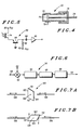
- the shutters 14, 30 associated with each of the output and input ports 10, 12 and 26, 28 are implemented as mechanical shutters formed by a rotatable glass prism 100 located in the path of light to or from the output ports 10, 12 or input ports 34, 36 respectively.
- the prism In a first position as shown in FIG. 7(a), corresponding to the shutter being open, the prism is positioned with parallel faces 102, 104 each perpendicular to and intersecting with a light path 106, so that the light passes directly through the prism with substantially no reflection.
- a second position as shown in FIG.
- the prism is rotated through approximately 90° about an axis through its center 108 perpendicular to the plane of the drawing so that parallel faces 110, 112 intersect the light path 106 at an acute angle.
- the faces 110, 112 are coated with a reflective layer such as gold or aluminum so that substantially all of the light incident upon the prism is reflected with substantially no transmission.
- a reflective layer such as gold or aluminum
- F12-F-E-1 by DiCon Fiberoptics, Inc., 44140 Warm Springs Boulevard., Fremont, California 94539, in which an output optical fiber is moved into and out of alignment with an input optical fiber so as to be transmissive or non-transmissive to to an optical signal therefrom.
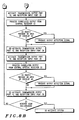
- FIG. 8 shows a flow chart illustrating the operation of the signal processor 52, in use of the object detection system 4 shown in FIG. 1, the system is enabled when the automobile begins reversing, e.g. when reverse gear is engaged.
- the signal processor 52 firstly activates the central transmitter light source 6, and simultaneously activates the transmission shutter 14 associated with the transmission output port 10 and also the reception shutter 30 associated with the reception input port 26. Light is thus transmitted from the output port 10 and illuminates the transmission field 18.
- any signal produced from the optical receiver 22 in response to this activation is buffered by the receiver circuit 48, correlated with the transmitter activation signal (so as to minimize errors in detection) by the correlator circuit 50, and processed by the signal processor 52 to produce an output detection signal which may be used to activate a warning signal (e.g.
- the signal processor 52 then de-activates the central transmitter light source 6, the transmission shutter 14 associated with the transmission output port 10 and the reception shutter 30 associated with the reception input port 26.
- the signal processor 52 secondly activates the central transmitter light source 6, and simultaneously activates the transmission shutter 14 associated with the transmission output port 10 and also the reception shutter 30 associated with the reception input port 28. Light is thus transmitted from the output port 10 and illuminates the transmission field 18. If there is an object in the area of overlap 40 between the transmission field 18 and the reception field 36, the object will cause light transmitted in the field 18 to be reflected in the field 36 and the reflected light will be introduced into the reception optical fiber 24 at the input port 28 and will be received at the central optical receiver 22. If no object is present in the area of overlap 40, no light will be reflected.
- Any signal produced from the optical receiver 22 in response to this activation is buffered by the receiver circuit 48, correlated with the transmitter activation signal by the correlator circuit 50, and processed by the signal processor 52 to produce an output detection signal which may be used in the ways described above.
- the signal processor 52 then de-activates the central transmitter light source 6, the transmission shutter 14 associated with the transmission output port 10 and the reception shutter 30 associated with the reception input port 28.
- the signal processor 52 thirdly activates the central transmitter light source 6, and simultaneously activates the transmission shutter 14 associated with the transmission output port 12 and also the reception shutter 30 associated with the reception input port 26. Light is thus transmitted from the output port 12 and illuminates the transmission field 20. If there is an object in the area of overlap 42 between the transmission field 20 and the reception field 34, the object will cause light transmitted in the field 20 to be reflected in the field 34 and the reflected light will be introduced into the reception optical fiber 24 at the input port 26 and will be received at the central optical receiver 22. If no object is present in the area of overlap 42, no light will be reflected.
- any signal produced from the optical receiver 22 in response to this activation is buffered by the receiver circuit 48, correlated with the transmitter activation signal by the correlator circuit 50, and processed by the signal processor 52 to produce an output detection signal which may be used in the ways described above.
- the signal processor 52 then de-activates the central transmitter light source 6, the transmission shutter 14 associated with the transmission output port 12 and the reception shutter 30 associated with the reception input port 26.
- the signal processor 52 fourthly activates the central transmitter light source 6, and simultaneously activates the transmission shutter 14 associated with the transmission output port 12 and also the reception shutter 30 associated with the reception input port 28. Light is thus transmitted from the output port 12 and illuminates the transmission field 20. If there is an object in the area of overlap 44 between the transmission field 20 and the reception field 36, the object will cause light transmitted in the field 20 to be reflected in the field 36 and the reflected light will be introduced into the reception optical fiber 24 at the input port 28 and will be received at the central optical receiver 22. If no object is present in the area of overlap 44, no light will be reflected.
- any signal produced from the optical receiver 22 in response to this activation is buffered by the receiver circuit 48, correlated with the transmitter activation signal by the correlator circuit 50, and processed by the signal processor 52 to produce an output detection signal which may be used in the ways described above.
- the signal processor 52 then de-activates the central transmitter light source 6, the transmission shutter 14 associated with the transmission output port 12 and the reception shutter 30 associated with the reception input port 28.
- the signal processor 52 then begins again the above described cycle of activation to detect objects present in the areas of overlap 38, 40, 42 and 44.
- the cycle is repeated continually until the automobile stops reversing, e.g. when reverse gear is disengaged.
- the signal processor 52 may be conveniently implemented in the form of a high-speed, integrated circuit digital signal processor to optimize system performance, size, power consumption and reliability.
- a range of such digital signal processors is available, and the choice and programming of a particular suitable digital signal processor to carry out the operation shown in the flow chart of FIG. 8 is fully within the ordinary competence of a person skilled in the art, and so will not be described further herein.
- the signal processor 52 may in future be implemented in the form of an optical processor.
- the central transmitter light source 6 need not be de-activated and re-activated with respective de-activations and re-activations of the shutters 12 and 30, but may instead be continuously activated while the system is in operation.
- the system may be activated when the car is stationary and in neutral gear or a forward gear, e.g. at a stop light, to warn the driver of other vehicles which may come close.
- light of any frequency may be used for transmission and reception in the system.
- the term “light” is used the term should not be construed as limiting the frequency used to the visible part of the spectrum; the "light” can be of any frequency (e.g. having a wavelength in the range 0.1 ⁇ m - 100 ⁇ m) that can be carried by an optical fiber.
- light of a lower frequency e.g. infra-red
- light of a higher frequency e.g. ultra-violet
- the object detection system described above affords high levels of design flexibility, and operational durability and reliability, since the light source 6 and the light receiver 22 (together with the associated electrical circuits 46, 48, 50 and 52) can be mounted inboard in the automobile at any desired location, free from harsh physical conditions, the optical fibers 8 and 24 coupling the inboard components to the peripheral ports in the fibers and their associated lenses and shutters.
- optical fibers could be of any inorganic or organic compounds which can be formed into an optical waveguide (e.g.plastic or glass) and could be easily bent to conform to the shape of the automobile body or bumper.
- optical waveguide e.g. plastic or glass
- an optical spectral filter may be employed to filter received light in the range to which the receiver 74 is responsive (e.g. in the wavelength range 0.8 ⁇ 0.05 ⁇ m).
- the spectral filters may be integrated into the material of the lenses 16, 32 (e.g. the lenses may be made of glass of the designation R6870 sold by Schott Glass Technologies, Inc., 400 York Avenue, Duryea, Pennsylvania 18642).
- the system could be expanded or adapted to cover any desired angle as required.
- the system could cover the sides and the complete front and rear bumpers.
- the system could also cover the underside of the automobile.
- the transmitter output ports and receiver input ports can be aligned in, or moved to cover, more than one plane if desired, so as to give optimal detection coverage for a particular application. For example for use at very close range it may be desired to move the transmitter output ports and receiver input ports so as to provide detection coverage very near to the ground. It will further be appreciated that, if desired, the pattern of detection coverage could be adapted to suit the speed and steering of the automobile.
- post-reception integration of the received signal may be performed in the signal processor 52 to reduce susceptibility of the system to spurious, short duration light signals.
- the transmitted optical signal could be modulated or coded as desired and the receiver circuitry could be arranged to respond only to received signals having the appropriate modulation or coding.
- an object detection system as described above offers the advantages of multiple fields of view with a single transmitter source and a single receiver detection circuit, low system cost since the system comprises few parts, and high reliability and simplicity of implementation since the system is simple and consists of parts from a mature technology base.
Landscapes
- Physics & Mathematics (AREA)
- Engineering & Computer Science (AREA)
- Electromagnetism (AREA)
- Computer Networks & Wireless Communication (AREA)
- General Physics & Mathematics (AREA)
- Radar, Positioning & Navigation (AREA)
- Remote Sensing (AREA)
- Optical Radar Systems And Details Thereof (AREA)
Applications Claiming Priority (2)
| Application Number | Priority Date | Filing Date | Title |
|---|---|---|---|
| US07/475,543 US5291261A (en) | 1990-02-06 | 1990-02-06 | Optical object detection system incorporating fiber optic coupling |
| US475543 | 1995-06-07 |
Publications (2)
| Publication Number | Publication Date |
|---|---|
| EP0441555A2 true EP0441555A2 (fr) | 1991-08-14 |
| EP0441555A3 EP0441555A3 (en) | 1992-09-23 |
Family
ID=23888045
Family Applications (1)
| Application Number | Title | Priority Date | Filing Date |
|---|---|---|---|
| EP19910300858 Withdrawn EP0441555A3 (en) | 1990-02-06 | 1991-02-04 | System for the detection of objects |
Country Status (2)
| Country | Link |
|---|---|
| US (1) | US5291261A (fr) |
| EP (1) | EP0441555A3 (fr) |
Cited By (9)
| Publication number | Priority date | Publication date | Assignee | Title |
|---|---|---|---|---|
| WO1993007511A1 (fr) * | 1991-09-30 | 1993-04-15 | Mitron Oy | Procede utilise avec un detecteur de proximite a acionnement optique |
| EP0566027A1 (fr) * | 1992-04-14 | 1993-10-20 | CARELLO S.p.A. | Système pour surveiller la zone autour d'un véhicule |
| GB2323491A (en) * | 1996-06-24 | 1998-09-23 | Mitsui Shipbuilding Eng | Laser obstacle detection |
| WO2000029870A1 (fr) * | 1998-11-16 | 2000-05-25 | Siemens Aktiengesellschaft | Commutateur optique de proximite |
| DE10106998A1 (de) * | 2000-11-04 | 2002-05-29 | Stefan Reich | Verfahren und Vorrichtung zur optischen Objekterfassung |
| EP2216661A1 (fr) * | 2009-02-09 | 2010-08-11 | Pepperl + Fuchs GmbH | Capteur optique destiné au contrôle d'objets dans une zone de surveillance |
| DE19749397B4 (de) * | 1996-11-13 | 2015-11-19 | Volkswagen Ag | Sichtabstandssensor |
| WO2018060407A1 (fr) * | 2016-09-29 | 2018-04-05 | Valeo Schalter Und Sensoren Gmbh | Dispositif de détection pour un véhicule automobile, pièce rapportée ainsi que véhicule automobile |
| EP3495845A1 (fr) * | 2017-12-07 | 2019-06-12 | Sick AG | Capteur optoélectronique et procédé de détection d'une zone de surveillance |
Families Citing this family (29)
| Publication number | Priority date | Publication date | Assignee | Title |
|---|---|---|---|---|
| JP3564800B2 (ja) * | 1994-08-30 | 2004-09-15 | 株式会社デンソー | 距離測定装置 |
| US5777563A (en) * | 1995-10-10 | 1998-07-07 | Chrysler Corporation | Method and assembly for object detection by a vehicle |
| DE10110420A1 (de) * | 2001-03-05 | 2002-09-12 | Sick Ag | Vorrichtung zur Bestimmung eines Abstandsprofils |
| US6919819B1 (en) * | 2003-02-14 | 2005-07-19 | Power Data Communication Co., Ltd. | Sunshade board |
| DE10342836A1 (de) * | 2003-09-17 | 2005-04-28 | Adc Automotive Dist Control | Umgebungserfassungssystem mit zwei beabstandeten Sendern und Empfängern |
| WO2005073754A1 (fr) * | 2004-02-02 | 2005-08-11 | Sjoenell Goeran | Detecteur de collision pour vehicule |
| USRE46672E1 (en) | 2006-07-13 | 2018-01-16 | Velodyne Lidar, Inc. | High definition LiDAR system |
| CN101581783B (zh) * | 2008-05-16 | 2013-04-17 | 深圳市迈测科技有限公司 | 一种相位测量的校准方法、装置及测距设备 |
| EP2228619A1 (fr) * | 2009-03-12 | 2010-09-15 | MBDA UK Limited | Fusée de proximité optique |
| US8757064B2 (en) * | 2008-08-08 | 2014-06-24 | Mbda Uk Limited | Optical proximity fuze |
| NL2006876C2 (nl) * | 2011-05-31 | 2012-12-03 | Phyco Trading B V | Voertuig, systeem voor het ontvangen en verzenden van optische signalen, alsmede werkwijzen. |
| NL2009901C2 (nl) * | 2012-11-29 | 2014-06-04 | Phyco Trading B V | Voertuig. |
| US10627490B2 (en) | 2016-01-31 | 2020-04-21 | Velodyne Lidar, Inc. | Multiple pulse, LIDAR based 3-D imaging |
| CN109154661A (zh) | 2016-03-19 | 2019-01-04 | 威力登激光雷达有限公司 | 用于基于lidar的3-d成像的集成照射和检测 |
| US10393877B2 (en) | 2016-06-01 | 2019-08-27 | Velodyne Lidar, Inc. | Multiple pixel scanning LIDAR |
| US10598770B2 (en) | 2016-07-28 | 2020-03-24 | GM Global Technology Operations LLC | Distributed vehicle LiDAR system |
| WO2018183843A1 (fr) | 2017-03-31 | 2018-10-04 | Velodyne Lidar, Inc. | Commande de puissance d'éclairage à lidar intégré |
| CN109387819A (zh) * | 2017-08-03 | 2019-02-26 | 北京北科天绘科技有限公司 | 一种激光雷达装置及其通道选通方法 |
| CN110809704B (zh) | 2017-05-08 | 2022-11-01 | 威力登激光雷达美国有限公司 | Lidar数据获取与控制 |
| WO2019099490A1 (fr) * | 2017-11-14 | 2019-05-23 | Continental Automotive Systems, Inc. | Ensemble capteur lidar flash |
| US11294041B2 (en) | 2017-12-08 | 2022-04-05 | Velodyne Lidar Usa, Inc. | Systems and methods for improving detection of a return signal in a light ranging and detection system |
| US10429495B1 (en) | 2018-04-03 | 2019-10-01 | Hesai Photonics Technology Co., Ltd. | Lidar system and method |
| WO2019237581A1 (fr) | 2018-06-13 | 2019-12-19 | Hesai Photonics Technology Co., Ltd. | Systèmes et procédés lidar |
| US11971507B2 (en) | 2018-08-24 | 2024-04-30 | Velodyne Lidar Usa, Inc. | Systems and methods for mitigating optical crosstalk in a light ranging and detection system |
| US10712434B2 (en) | 2018-09-18 | 2020-07-14 | Velodyne Lidar, Inc. | Multi-channel LIDAR illumination driver |
| US11082010B2 (en) | 2018-11-06 | 2021-08-03 | Velodyne Lidar Usa, Inc. | Systems and methods for TIA base current detection and compensation |
| US12061263B2 (en) | 2019-01-07 | 2024-08-13 | Velodyne Lidar Usa, Inc. | Systems and methods for a configurable sensor system |
| US11885958B2 (en) | 2019-01-07 | 2024-01-30 | Velodyne Lidar Usa, Inc. | Systems and methods for a dual axis resonant scanning mirror |
| US10613203B1 (en) | 2019-07-01 | 2020-04-07 | Velodyne Lidar, Inc. | Interference mitigation for light detection and ranging |
Family Cites Families (13)
| Publication number | Priority date | Publication date | Assignee | Title |
|---|---|---|---|---|
| US3327584A (en) * | 1963-09-09 | 1967-06-27 | Mechanical Tech Inc | Fiber optic proximity probe |
| DE3010137A1 (de) * | 1980-03-15 | 1981-09-24 | Licentia Patent-Verwaltungs-Gmbh, 6000 Frankfurt | Lichtoptische einrichtung zur messung des abstandes zwischen der oberflaeche eines messobjektes und einer festen bezugsebene |
| US4515479A (en) * | 1980-07-29 | 1985-05-07 | Diffracto Ltd. | Electro-optical sensors with fiber optic bundles |
| JPS587581A (ja) * | 1981-07-08 | 1983-01-17 | Nissan Motor Co Ltd | 光レ−ダ式通り抜け判別装置 |
| JPS58171686A (ja) * | 1982-04-01 | 1983-10-08 | Ricoh Co Ltd | 検出装置 |
| JPS58201015A (ja) * | 1982-05-20 | 1983-11-22 | Canon Inc | 測距装置 |
| JPS58211677A (ja) * | 1982-06-02 | 1983-12-09 | Nissan Motor Co Ltd | 光レ−ダ装置 |
| US4653905A (en) * | 1985-08-21 | 1987-03-31 | Newport Corporation | Fiber optic range finder systems |
| US4692611A (en) * | 1986-01-29 | 1987-09-08 | Mechanical Technology Incorporated | Fiber optic proximity sensor with feedback servo imaging means |
| JPH0616147B2 (ja) * | 1986-03-26 | 1994-03-02 | チノン株式会社 | カメラ |
| US4752799A (en) * | 1986-07-07 | 1988-06-21 | Honeywell Inc. | Optical proximity sensing optics |
| US4766323A (en) * | 1986-08-29 | 1988-08-23 | B. C. Hydro | Method and apparatus for determining the distance of an object |
| DE3635396A1 (de) * | 1986-10-17 | 1988-04-28 | Bayerische Motoren Werke Ag | Vorrichtung zum erkennen von hindernissen fuer kraftfahrzeuge |
-
1990
- 1990-02-06 US US07/475,543 patent/US5291261A/en not_active Expired - Fee Related
-
1991
- 1991-02-04 EP EP19910300858 patent/EP0441555A3/en not_active Withdrawn
Cited By (13)
| Publication number | Priority date | Publication date | Assignee | Title |
|---|---|---|---|---|
| WO1993007511A1 (fr) * | 1991-09-30 | 1993-04-15 | Mitron Oy | Procede utilise avec un detecteur de proximite a acionnement optique |
| US5541403A (en) * | 1991-09-30 | 1996-07-30 | Mitron Oy | Method in an optically operated proximity switch |
| EP0566027A1 (fr) * | 1992-04-14 | 1993-10-20 | CARELLO S.p.A. | Système pour surveiller la zone autour d'un véhicule |
| GB2323491A (en) * | 1996-06-24 | 1998-09-23 | Mitsui Shipbuilding Eng | Laser obstacle detection |
| GB2323491B (en) * | 1996-06-24 | 1999-03-31 | Mitsui Shipbuilding Eng | Laser obstacle detection method and sensor |
| DE19749397B4 (de) * | 1996-11-13 | 2015-11-19 | Volkswagen Ag | Sichtabstandssensor |
| WO2000029870A1 (fr) * | 1998-11-16 | 2000-05-25 | Siemens Aktiengesellschaft | Commutateur optique de proximite |
| DE10106998A1 (de) * | 2000-11-04 | 2002-05-29 | Stefan Reich | Verfahren und Vorrichtung zur optischen Objekterfassung |
| DE10106998C2 (de) * | 2000-11-04 | 2003-01-23 | Stefan Reich | Verfahren und Vorrichtung zur optischen Objekterfassung |
| EP2216661A1 (fr) * | 2009-02-09 | 2010-08-11 | Pepperl + Fuchs GmbH | Capteur optique destiné au contrôle d'objets dans une zone de surveillance |
| WO2018060407A1 (fr) * | 2016-09-29 | 2018-04-05 | Valeo Schalter Und Sensoren Gmbh | Dispositif de détection pour un véhicule automobile, pièce rapportée ainsi que véhicule automobile |
| US11543492B2 (en) | 2016-09-29 | 2023-01-03 | Valeo Schalter Und Sensoren Gmbh | Detection device for a motor vehicle, attached part and motor vehicle |
| EP3495845A1 (fr) * | 2017-12-07 | 2019-06-12 | Sick AG | Capteur optoélectronique et procédé de détection d'une zone de surveillance |
Also Published As
| Publication number | Publication date |
|---|---|
| EP0441555A3 (en) | 1992-09-23 |
| US5291261A (en) | 1994-03-01 |
Similar Documents
| Publication | Publication Date | Title |
|---|---|---|
| US5291261A (en) | Optical object detection system incorporating fiber optic coupling | |
| US4447800A (en) | Obstacle detector for use in vehicles | |
| EP0505028B2 (fr) | Appareil détecteur de proximité | |
| US20140160460A1 (en) | Flash ladar collision avoidance system | |
| JPS63120275A (ja) | 動力車の障害物認識装置 | |
| NL2009901C2 (nl) | Voertuig. | |
| JPS6243543A (ja) | ウインドガラスの水滴検出装置 | |
| US4986631A (en) | Automotive display system | |
| CN106627379A (zh) | 汽车变道盲区报警信号控制系统及装置 | |
| KR100559421B1 (ko) | 차량 추돌 방지 시스템 | |
| CN110103810B (zh) | 三维探测照明系统及汽车 | |
| WO2023040788A1 (fr) | Radar laser, dispositif de détection et véhicule | |
| JP2002534662A (ja) | 透明プレート表面上の汚れを検出するための検出器 | |
| US20250298132A1 (en) | Lidar and movable device | |
| JP2822801B2 (ja) | 車両用通信装置 | |
| CN208198262U (zh) | 低能见度条件下汽车全方位防追尾及碰撞系统 | |
| EP4575560A1 (fr) | Appareil de détection et dispositif terminal | |
| Najm | Comparison of alternative crash-avoidance sensor technologies | |
| CN216622697U (zh) | 车载激光雷达和带有车载激光雷达的车辆 | |
| JPH0720229A (ja) | レーザーレーダー装置 | |
| KR100255173B1 (ko) | 스케닝 레이져 레이더 | |
| CN222913861U (zh) | 收发光路系统、激光雷达及车辆 | |
| CN220773255U (zh) | 一种测距装置及机器人 | |
| US12287074B2 (en) | Infrared lamp device and infrared lamp system for a vehicle | |
| JPS6196484A (ja) | 光反射型物体検出装置 |
Legal Events
| Date | Code | Title | Description |
|---|---|---|---|
| PUAI | Public reference made under article 153(3) epc to a published international application that has entered the european phase |
Free format text: ORIGINAL CODE: 0009012 |
|
| AK | Designated contracting states |
Kind code of ref document: A2 Designated state(s): DE FR GB |
|
| PUAL | Search report despatched |
Free format text: ORIGINAL CODE: 0009013 |
|
| AK | Designated contracting states |
Kind code of ref document: A3 Designated state(s): DE FR GB |
|
| STAA | Information on the status of an ep patent application or granted ep patent |
Free format text: STATUS: THE APPLICATION HAS BEEN WITHDRAWN |
|
| 18W | Application withdrawn |
Withdrawal date: 19930601 |