EP0441596B1 - Vorrichtung zum Auftragen von Bildern - Google Patents
Vorrichtung zum Auftragen von Bildern Download PDFInfo
- Publication number
- EP0441596B1 EP0441596B1 EP91300935A EP91300935A EP0441596B1 EP 0441596 B1 EP0441596 B1 EP 0441596B1 EP 91300935 A EP91300935 A EP 91300935A EP 91300935 A EP91300935 A EP 91300935A EP 0441596 B1 EP0441596 B1 EP 0441596B1
- Authority
- EP
- European Patent Office
- Prior art keywords
- web
- stock
- images
- reservoir
- transferring
- Prior art date
- Legal status (The legal status is an assumption and is not a legal conclusion. Google has not performed a legal analysis and makes no representation as to the accuracy of the status listed.)
- Expired - Lifetime
Links
- 239000000463 material Substances 0.000 claims description 14
- 239000000853 adhesive Substances 0.000 claims description 13
- 230000001070 adhesive effect Effects 0.000 claims description 13
- 238000011144 upstream manufacturing Methods 0.000 claims description 12
- 230000001133 acceleration Effects 0.000 claims description 6
- 238000000926 separation method Methods 0.000 claims description 4
- 230000000694 effects Effects 0.000 claims description 3
- 238000003825 pressing Methods 0.000 claims 1
- 239000010409 thin film Substances 0.000 description 6
- 229920002799 BoPET Polymers 0.000 description 2
- 239000005041 Mylar™ Substances 0.000 description 2
- 229910000831 Steel Inorganic materials 0.000 description 2
- 238000001035 drying Methods 0.000 description 2
- 238000012986 modification Methods 0.000 description 2
- 230000004048 modification Effects 0.000 description 2
- 239000004033 plastic Substances 0.000 description 2
- 229920003023 plastic Polymers 0.000 description 2
- 239000005020 polyethylene terephthalate Substances 0.000 description 2
- 229920000139 polyethylene terephthalate Polymers 0.000 description 2
- 239000010959 steel Substances 0.000 description 2
- 239000002699 waste material Substances 0.000 description 2
- VYPSYNLAJGMNEJ-UHFFFAOYSA-N Silicium dioxide Chemical compound O=[Si]=O VYPSYNLAJGMNEJ-UHFFFAOYSA-N 0.000 description 1
- 239000002131 composite material Substances 0.000 description 1
- 230000006835 compression Effects 0.000 description 1
- 238000007906 compression Methods 0.000 description 1
- 238000000034 method Methods 0.000 description 1
- 230000005855 radiation Effects 0.000 description 1
- 229910052814 silicon oxide Inorganic materials 0.000 description 1
- 230000001360 synchronised effect Effects 0.000 description 1
Images


Classifications
-
- B—PERFORMING OPERATIONS; TRANSPORTING
- B41—PRINTING; LINING MACHINES; TYPEWRITERS; STAMPS
- B41F—PRINTING MACHINES OR PRESSES
- B41F19/00—Apparatus or machines for carrying out printing operations combined with other operations
- B41F19/02—Apparatus or machines for carrying out printing operations combined with other operations with embossing
- B41F19/06—Printing and embossing between a negative and a positive forme after inking and wiping the negative forme; Printing from an ink band treated with colour or "gold"
- B41F19/062—Presses of the rotary type
-
- B—PERFORMING OPERATIONS; TRANSPORTING
- B65—CONVEYING; PACKING; STORING; HANDLING THIN OR FILAMENTARY MATERIAL
- B65C—LABELLING OR TAGGING MACHINES, APPARATUS, OR PROCESSES
- B65C9/00—Details of labelling machines or apparatus
- B65C9/08—Label feeding
- B65C9/18—Label feeding from strips, e.g. from rolls
- B65C9/1865—Label feeding from strips, e.g. from rolls the labels adhering on a backing strip
- B65C9/1869—Label feeding from strips, e.g. from rolls the labels adhering on a backing strip and being transferred directly from the backing strip onto the article
-
- B—PERFORMING OPERATIONS; TRANSPORTING
- B41—PRINTING; LINING MACHINES; TYPEWRITERS; STAMPS
- B41P—INDEXING SCHEME RELATING TO PRINTING, LINING MACHINES, TYPEWRITERS, AND TO STAMPS
- B41P2219/00—Printing presses using a heated printing foil
- B41P2219/50—Printing presses using a heated printing foil combined with existing presses
- B41P2219/51—Converting existing presses to foil printing presses
-
- B—PERFORMING OPERATIONS; TRANSPORTING
- B65—CONVEYING; PACKING; STORING; HANDLING THIN OR FILAMENTARY MATERIAL
- B65C—LABELLING OR TAGGING MACHINES, APPARATUS, OR PROCESSES
- B65C9/00—Details of labelling machines or apparatus
- B65C2009/0081—Means for forming a label web buffer, e.g. label web loop
-
- Y—GENERAL TAGGING OF NEW TECHNOLOGICAL DEVELOPMENTS; GENERAL TAGGING OF CROSS-SECTIONAL TECHNOLOGIES SPANNING OVER SEVERAL SECTIONS OF THE IPC; TECHNICAL SUBJECTS COVERED BY FORMER USPC CROSS-REFERENCE ART COLLECTIONS [XRACs] AND DIGESTS
- Y10—TECHNICAL SUBJECTS COVERED BY FORMER USPC
- Y10T—TECHNICAL SUBJECTS COVERED BY FORMER US CLASSIFICATION
- Y10T156/00—Adhesive bonding and miscellaneous chemical manufacture
- Y10T156/17—Surface bonding means and/or assemblymeans with work feeding or handling means
- Y10T156/1702—For plural parts or plural areas of single part
- Y10T156/1705—Lamina transferred to base from adhered flexible web or sheet type carrier
- Y10T156/1707—Discrete spaced laminae on adhered carrier
- Y10T156/171—Means serially presenting discrete base articles or separate portions of a single article
-
- Y—GENERAL TAGGING OF NEW TECHNOLOGICAL DEVELOPMENTS; GENERAL TAGGING OF CROSS-SECTIONAL TECHNOLOGIES SPANNING OVER SEVERAL SECTIONS OF THE IPC; TECHNICAL SUBJECTS COVERED BY FORMER USPC CROSS-REFERENCE ART COLLECTIONS [XRACs] AND DIGESTS
- Y10—TECHNICAL SUBJECTS COVERED BY FORMER USPC
- Y10T—TECHNICAL SUBJECTS COVERED BY FORMER US CLASSIFICATION
- Y10T156/00—Adhesive bonding and miscellaneous chemical manufacture
- Y10T156/17—Surface bonding means and/or assemblymeans with work feeding or handling means
- Y10T156/1702—For plural parts or plural areas of single part
- Y10T156/1712—Indefinite or running length work
- Y10T156/1734—Means bringing articles into association with web
Definitions
- This invention relates to an image applying apparatus.
- the invention finds particular but not exclusive use in a method of applying security images to banknotes.
- a holographic image usually carried in the form of a thin film of material, in credit cards in order to make counterfeiting more difficult.
- Use of such images in banknotes, for the same purpose, has also been proposed.
- the present invention is intended for use in application of holographic images.
- apparatus for applying images to a moving stock includes means for conveying a carrier web, said web carrying transferable images, means for conveying a stock to which the images are to be applied, means for advancing the stock at a controlled speed, means for advancing the web at a variable speed, and means for transferring the images to predetermined positions of the stock, said web advancing means including means for moving the web at the speed of the stock while images are being transferred and means for moving the web at a lower speed at other times so as to reduce net travel of the web between successive transferring steps, said moving means including means for reversing motion of the web, characterised in that said reversing means comprises web drive means arranged downstream of the transferring means and pneumatic means arranged upstream of the transferring means for assisting reversal of the web, and in that the web passes through a web reservoir arranged upstream of the transfer means, the reservoir accumulating web during reverse movement thereof.
- the web is accelerated from rest up to the speed of the stock and decelerated back to rest between each application.
- the web is retracted after deceleration by an amount just sufficient to allow acceleration of the next image up to the speed of the stock at the application position.
- the net distance travelled by the web during each cycle is substantially equal to (including only slightly exceeding) the length of an image on the web.
- the spacing (i.e. of corresponding portions) of the images on the web need bear no relationship to the spacing of said positions on the stock.
- the images carried by the web may comprise discrete images or a continuous image (which becomes separated on transfer to the stock). In the latter case it is particularly important that the net distance travelled by the web in excess of the length of an individual part of the image transferred be minimised in order to minimise waste of relatively expensive image material.
- the web and the stock are pressed together to apply the images to the stock.
- the stock has adhesive ink patches applied at the predetermined positions in order to facilitate application of the images to the stock.
- the image part applied at each position may be determined by the adhesive patches: in other words, separation of an individual transferred image part from the web occurs where it is pressed on to the adhesive patch, thereby separating said part from the remaining image on the web. It has been found that using the adhesive patches in this way to define the transferred image, with no prior separation lines in the continuous image on the web, does produce images on the stock with sufficiently well-defined ends.
- the web may carry discrete images, where image parts to be transferred already have lines of separation (or spaces) between them on the web.
- the invention is particularly applicable to the application of holographic images (holograms) to banknote sheets.
- images may be carried in the form of composite layers on plastics web from which they are readily transferred to suitably prepared areas (the predetermined positions) on the sheets.
- the images comprise five alternate layers of leuconium oxide and silicon oxide carried on a web of PET (e.g. Mylar or Melinex).
- PET e.g. Mylar or Melinex
- the image material is relatively expensive: it is also generally easier to apply to the web as a continuous layer (or layers). Even when discrete images are applied to the web it is impractical to attempt to space these at the distances required on the sheets. Hence it is preferred that the images are closely spaced (or continuous) on the web irrespective of their final spacing on the sheets.
- the stock may comprise material in sheet or web form.
- the apparatus of the invention may include independent drives for the carrier and for the stock.
- the drive for the carrier comprises an electronically-controlled servo motor receiving timing pulses from the drive for the stock.
- the drive for the stock preferably comprises a constant speed motor.
- the web may pass through an air mover upstream of the position at which the images are applied to the stock, the air mover being preferably capable of assisting retracting of the web.
- the reservoir may be arranged to accumulate web during periods when the web is travelling at said lower speed.
- Suction means may be provided in the reservoir to assist retraction of the web.
- Linked drive means e.g. capstan rollers
- Means for applying the images may comprise opposed cylinders which press the web and the stock together, the cylinders being arranged so that pressure is applied between the web and the stock only at positions corresponding to said predetermined positions on the stock where the images are to be applied. In this way the cylinders may be rotated at a constant speed corresponding to the speed of the stock, whereas the web may be moved at a different speed other than when an image is being applied.
- the stock may comprise sheets containing an array of, say, forty banknotes arranged in four transverse rows of ten. If it is required to apply an image to each banknote there would then be ten webs for applying images to the sheets.
- a common drive system may be provided for each of the webs, possibly with individual tensioning means for each web.
- the web carries security images it is preferably fed from a cassette unit for application of the image to the stock and subsequently rewound on to a cassette unit after application. In this way security for unapplied images remaining on the used web is more easily maintained.
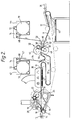
- the security printing apparatus comprises a unit 10 for feeding successive sheets (13, Figure 2) of banknote paper (which may be at least partially pre-printed) from a stack 11.
- the unit 10 is arranged for stack replenishment from a trolley 12.
- Individual sheets are conveyed from the feeding unit 10 by an outfeed belt 14 to a position where each sheet is engaged by a precision belt or chain conveyor 16 which carries a series of transverse bars (17, Figure 2) incorporating individual sheet grippers.
- the grippers may be scissors type and spring-loaded, and may be activated at appropriate positions along the path of the conveyor 16 by cams mounted along each side of the path so that each sheet is gripped at its leading edge.
- the conveyor 16 carries the sheets 13 through the entire subsequent part of the apparatus, preferably at a constant speed, and maintains positional accuracy of individual sheets during subsequent processing.
- Sheets 13 may be given vertical restraint by laterally-spaced wires 19,21 which extend longitudinally along the operative runs of conveyor 16.
- any known conveyor for conveying individual sheets in well defined positions may be used.
- successive sheets 13 are moved by the conveyor 16 past a printing unit 18, which includes a gravure print cylinder 20, and offset cylinder 22 and an impression cylinder 24.
- the offset and impression cylinders 22, 24 each have cut-outs 26 in their peripheries to allow passage of the transverse bars 17 of the conveyor 16.
- the unit 18 is effective to apply a series of patches of adhesive ink to each sheet, e.g. one patch for each banknote on the sheet.
- the unit 18 may apply patches in a pattern of ten transversely-spaced rows by four longitudinally-spaced patches (i.e. the gravure cylinder 20 has four circumferentially-spaced rows each of ten individual print patterns).
- Another possibility is an arrangement of eight transversely-spaced rows of five longitudinally-spaced patches.
- the conveyor 16 Downstream of the print unit 18 the conveyor 16 carries the sheets through an ultra-violet radiation drying unit 28 and then along an extended path 30 between the drying unit and an applicator device 32, at which device individual pieces of thin film security material (i.e. carrying holographic images) are transferred from transversely-spaced carrying ribbons 34 on to the adhesive patches carried by the banknote sheets. Satisfactory sheets are subsequently conveyed by the conveyor 16 to a stacking unit 36. Faulty sheets (i.e. those having no or incorrectly applied thin film security material) are detected by a sensor 38 and caused to be diverted to a faulty sheet stack 40.
- Faulty sheets i.e. those having no or incorrectly applied thin film security material
- the thin film security material is carried on each ribbon 34 in the form of a continuous image separated into individual images (on transfer) by action of the adhesive patches. Alternatively, individual (separate) transferable images could be carried on each ribbon 34.
- the ribbons 34 are each conveyed from a cassette unit 42 to the applicator device 32 and then rewound (after transfer of the images to the banknote sheets) in a further cassette unit 44.
- the ribbons 34 typically comprise PET plastics material (e.g. Mylar or Melinex).
- Each of the units 42 and 44 includes a reel drive but speed of the ribbon 34 through the applicator device 32 is controlled by a servo motor capstan drive which is controlled by timing signals generated by an encoder carried by a suitable part of the drive for the conveyor 16. The reel drives therefore serve to maintain each ribbon 34 within an acceptable range of tensions.
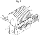
- the device 32 comprises an upper steel cylinder 46 and a lower rubber-coated steel cylinder 48.
- the cylinders 46 and 48 are synchronised with the conveyor 16 by means of a belt and gear drive 50.
- Each of the cylinders 46, 48 has a cut-out 52 to allow passage of the transverse bars 17 of the conveyor 16.
- the upper cylinder 46 has a series of transversely and circumferentially spaced recesses 54.
- Each circumferential series of recesses 54 is aligned with the path of a ribbon 34 (i.e. there are ten such circumferential series).
- the recesses 54 are separated by bridge pieces 56: these bridge pieces correspond approximately in size and spacing to those of the adhesive patches on the banknote sheets.
- the ribbons 34 are pressed on to the sheet between the drums 46 and 48 only while the adhesive patches and corresponding images (i.e. portions of the continuous images, comprising transferable pieces of the thin film security material) on the ribbons are aligned.
- the ribbons 34 are driven by upper and lower capstans 58, 60.
- the upper capstans 58 are arranged in two series of five, each being driven by a side-mounted servo motor 62 (only one of which is shown): in alternative arrangements there could be a single motor driving all the upper capstans 58, or more than two motors for these capstans.
- the positions of the bridge pieces 56, corresponding to those of the adhesive patches 56, are relatively widely spaced in the circumferential direction relative to the roller 46.
- the images on the ribbon 34 could be similarly spaced so that the motor 62 would run at a relatively constant speed with the ribbons 34 having a linear speed corresponding to that of the sheets conveyed by the conveyor 16.
- the motor 62 in effect indexes the images into position between the cylinders 46 and 48. It will be appreciated, however, that for successful application of the images the ribbons 34 should be travelling at the same speed as the banknote sheets at the instant that they are pressed onto the sheets by the bridge pieces 56.
- the control for the motors 62 causes the ribbons to be rapidly accelerated from rest up to the speed of the sheets and subsequently decelerated again. It will be further appreciated that although the acceleration and deceleration may be relatively rapid the length of each ribbon 34 conveyed by the capstans 58, 60 during each cycle needs to exceed the length of the image to be applied in order to allow for the acceleration before the image reaches the speed of the sheets and for the deceleration back to rest.
- each ribbon passes through an air mover 64 which continually imposes a relatively light conveying force away from the rollers 46, 48. This force is easily overcome by the drive of the capstans 58 during advancement of the ribbons 34 but is sufficient to retract the ribbons during reversal of the drive.
- Suitable air movers are disclosed in British patent specification No. 2226538A, to which reference is directed for details.
- a ribbon reservoir 63 ( Figure 2) arranged upstream of the air mover 64 receives ribbon 34 retracted beyond the air mover.
- the motor 62 receives timing signals from a shaft encoder associated with the drive for the sheet conveyor 16.
- the bridge pieces 56 on the upper cylinder 46 correspond in spacing and size to that of the adhesive patches on the banknote sheets they may exceed these in size somewhat, thereby providing a tolerance for drift in the position of the adhesive patches on the sheets.
- the transfer load between the cylinders 46 and 48 is imposed by a pair of pneumatic cylinders at the sides of the cylinders.
- the compression load can be pre-set by setting the supply pressure to these cylinders.
- the lower cylinder 48 is driven directly by the chain conveyor 16.
- the upper cylinder 46 is driven from the lower cylinder by a gear chain or toothed belt forming part of the drive 50.
- the drive arrangement to the ribbons 34 is readily able to deal with any splices in the ribbons.
- a decision can be made (e.g. by a control microprocessor) on when to increase the ribbon increment and by how much so as to minimise wastage of the thin film security material carried by the ribbons.
- Each reel in unit 42 may contain sufficient material to cope with one complete seven hour shift at 100% efficiency. In this way the necessity for automatic splicing is avoided, thereby simplifying the machine. Any material remaining on the machine at the end of each shift could be returned within the reel unit 42 to a refurbishing centre. With this arrangement typical reel diameter would be 400mm (for 3,750 metres of ribbon) and a typical weight of the unit 42 would be 70kg.
- the reels contained in unit 42 may be somewhat smaller, e.g. with enough material for half a shift, and an automatic splicing arrangement provided. With such an arrangement the diameter of the reel would be about 300mm and the weight of the unit 42 about 40kg. In either case it will be seen that closely spacing the transferable images on the ribbons 34 is advantageous.
- Tension in the ribbon 34 is controlled by individually driving each of the reels of ribbon by small inexpensive d.c. electric motors.
- the ribbons 34 run over rollers 68 on a sprung arm to which is attached a potentiometer.
- the output of the potentiometer controls motor torque, thereby achieving closed loop tension control.
- the reels are contained in the units 42, 44 within cassettes 70, and the electric drives are connected via bevelled gears to rubber rollers 72 which engage directly with the outer circumference of the cassettes to rotate them.
- the motors and associated ribbon rollers 68, 72 etc. are carried on a swinging arm 74 which may be swung clear of the cassettes when required.
- FIG. 4 shows an alternative arrangement for providing retraction of the ribbons 34.
- a modified ribbon reservoir 163 is located upstream of the cylinders 46, 48. At its downstream edge the reservoir 163 has an air bearing 165.
- Capstan rollers 100, 102 feed the ribbon 34 into the reservoir 163 (at the average rate of consumption of the ribbon).
- a loop of ribbon 34 formed in the reservoir 163 is subjected to suction generated by a suction manifold 104 in the base of the reservoir. The effect of this is that when drive to the capstans 58, 60 is reversed so as to allow retraction of the ribbons 34 the suction acting on the ribbons in the reservoir 163 ensures retraction of the ribbons between the cylinders 46, 48.
- the reservoir 163 thus performs the function of the air mover 64 in Figure 1.
- the air bearing 165 could generate a component of movement tending to cause retraction of the ribbons 34 and thus assist suction generated in the reservoir 163 (i.e. the air bearing 165 could partly have the function of an air mover).
- Figure 5 shows a different arrangement for causing retraction of the ribbons 34.
- a reservoir 163A similar to the reservoir 163, is provided, so that tension is controlled downstream and upstream of the print cylinders 46,48 by the reservoirs 163, 163A.
- Each of the reservoirs 163, 163A may include a suction manifold 104.
- capstan rollers 58A, 60A may be arranged upstream of the cylinders 46, 48.
- a common drive 106 is provided for the rollers 58, 60 and 58A, 60A.
- Feed capstan rollers 100, 102 are provided upstream of the capstan rollers 58A, 60A.
- the drive 106 when it is required to retract ribbons 34 the drive 106 is reversed so that rollers 58A, 60A ensure that ribbons are drawn in the reverse direction past the cylinders 46, 48.
- the reservoir 163 receives portions of ribbons 34 retracted by the rollers 58A, 60A (and possibly, in addition, portions of ribbons which continue to be advanced by rollers 100, 102).
- the drive 106 causes both sets of rollers 58, 60 and 58A, 60A to rotate at the same rate.
- a preferred way of achieving this supplementary drive comprises rotary eccentric rollers 58B, 60B which engage the web in a nip formed between them briefly during each revolution.
- Drive for the rollers 58B,60B may be independent or derived from the drive 106.
Landscapes
- Delivering By Means Of Belts And Rollers (AREA)
- Advancing Webs (AREA)
- Coating Apparatus (AREA)
Claims (16)
- Vorrichtung zum Auftragen von Bildern auf ein sich bewegendes Ausgangsmaterial, mit Mitteln (58,60,58A,60A,58B,60B) zum Fördern einer Trägerbahn (34), die übertragbare Bilder trägt, Mitteln (16) zum Fördern eines Ausgangsmaterials (13), auf das die Bilder aufgetragen werden, Mitteln zum Vorwärtsbewegen des Ausgangsmaterials mit geregelter Geschwindigkeit, Mitteln (106) zum Vorwärtsbewegen der Bahn mit veränderlicher Geschwindigkeit und Mitteln (46,48) zum Übertragen der Bilder auf vorgegebene Stellen des Ausgangsmaterials, wobei die Bahnvorwärtsbewegungsmittel Mittel, die die Bahn während der Übertragung der Bilder mit der Geschwindigkeit des Ausgangsmaterials bewegen, und Mittel, die die Bahn zu anderen Zeiten mit einer niedrigeren Geschwindigkeit bewegen, umfaßt, um die effektive Bewegungsstrecke der Bahn während aufeinanderfolgender Übertragungsschritte zu verringern, wobei die Bewegungsmittel Reversiermittel zum Reversieren der Bahnbewegung umfassen, dadurch gekennzeichnet, daß die Reversiermittel (58,60, 58A,60A,64;163) stromab der Übertragungsmittel (46,48) angeordnete Bahnantriebsmittel (58,60) und pneumatische Mittel (64;104,165) aufweisen, die stromauf der Übertragungsmittel angeordnet sind, um die Umkehr der Bahn zu unterstützen, und daß die Bahn durch einen Bahnspeicher (63;163) läuft, der stromauf der Übertragungsmittel angeordnet ist, wobei der Speicher die Bahn während ihrer Rückwärtsbewegung speichert.
- Vorrichtung nach Anspruch 1, mit einem auf der stromabwärtigen Seite des Speichers (63;163) angeordneten Luftbeweger (64;165), der die Bahn in eine Richtung in den Speicher hineindrückt.
- Vorrichtung nach Anspruch 1 oder 2, bei der der Bahnspeicher (163) mit Unterdruck versehen ist, um die Bahn in den Speicher einzuziehen.
- Vorrichtung nach Anspruch 3, bei der der Bahnspeicher (163) eine Kammer mit einer Öffnung, durch die die Bahn in Form einer Schleife verläuft, sowie Unterdruckmittel (104) aufweist, die auf die Schleife an ihrer von der Öffnung entfernten Seite einwirkt.
- Vorrichtung nach einem der vorhergehenden Ansprüche, bei der pneumatische Spannmittel (163a) für die Bahn stromab der Übertragungsmittel (46,48) vorgesehen sind.
- Vorrichtung nach einem der vorhergehenden Ansprüche, bei der die Ausgangsmaterial-Vorwärtsbewegungsmittel und die Bahnvorwärtsbewegungsmittel (106) unabhängige Antriebsmittel aufweisen, deren Synchronisation relativ zueinander durch elektronische Zeitsteuersignale erreicht wird.
- Vorrichtung nach einem der vorhergehenden Ansprüche, mit Mitteln (56), die zyklisch Druck auf die Bahn (34) und das Ausgangsmaterial (13) ausüben, um die Übertragung der Bilder zu bewirken.
- Vorrichtung nach Anspruch 7, bei der die Druckausübungsmittel einen Zylinder (46) mit einem Umfangsbereich umfassen, der zumindest einen relativ erhabenen Steg (56) zum Aufbringen des Drucks und mindestens eine Ausnehmung (54) aufweist, durch die die Bahn laufen kann.
- Vorrichtung nach einem der vorhergehenden Ansprüche, bei der die Mittel zum Fördern einer Trägerbahn Mittel zum Fördern mehrerer seitlich beabstandeter Trägerbahnen (34) umfassen und daß die Übertragungsmittel Mittel (56) umfassen, die seitlich beabstandete Bilder im wesentlichen gleichzeitig zu dem Ausgangsmaterial (13) übertragen.
- Vorrichtung nach einem der vorhergehenden Ansprüche, bei der die Bahnvorwärts-Bewegungsmittel Zusatzmittel (58b,60b) umfassen, die die Bahn (34) während nur eines Teils jedes Zyklus erfassen und so ausgebildet sind, daß sie die Trennung der Bahn und des Ausgangsmaterials (13) unmittelbar nach der Übertragung eines Bildes fördern.
- Vorrichtung nach einem der vorhergehenden Ansprüche, bei der die Materialfördermittel (16) Mittel zum Positionieren einzelner Blätter (13) umfassen und bei der die Bahnvorwärts-Bewegungsmittel (106) durch Zeitsteuersignale gesteuert werden, die von den Bahnvorwärts-Bewegungsmitteln abgeleitet sind.
- Vorrichtung nach einem der vorhergehenden Ansprüche, mit Mitteln (67) zum Feststellen einer Spleisstelle in einer Bahn (34) und zum Steuern der Bahnvorwärts-Bewegungsmittel (106) derart, daß die gespleiste Stelle der Bahn zwischen aufeinanderfolgenden Übertragungsschritten an den Übertragungsmitteln vorbei bewegt wird.
- Vorrichtung nach einem der vorhergehenden Ansprüche, bei der die Mittel zum Fördern der Trägerbahn (34) Mittel zur Ausgabe der Bahn aus einer Kassette (42) und zum Zurückführen der Bahn zu einer Kassette (44) nach der Übertragung von Bildern umfassen.
- Vorrichtung nach einem der vorhergehenden Ansprüche, mit Mitteln (18) zum Auftragen von Klebestreifen auf das Ausgangsmaterial (13) stromauf der Übertragungsmittel (46,48), wobei die Streifen an den besagten vorgegebenen Stellen angeordnet sind.
- Vorrichtung nach einem der vorhergehenden Ansprüche, bei der das Ausgangsmaterial aus bedrucktem Sicherheitsmaterial und die Bilder aus Sicherheitsbildern bestehen.
- Vorrichtung nach einem der vorhergehenden Ansprüche, bei der die Reversiermittel (58,60,58a,60a,64;163) die Bahn in jedem Zyklus eine Strecke bewegt, die derjenigen entspricht, die die Bahn während der Beschleunigung auf die Geschwindigkeit des Materials und während der Verzögerung von der Geschwindigkeit des Ausgangsmaterials vorwärtsbewegt wurde, so daß die effektive Strecke, die die Bahn bei jedem Zyklus zurückgelegt hat, im wesentlichen gleich der Wiederholungslänge eines Bildes ist.
Applications Claiming Priority (6)
| Application Number | Priority Date | Filing Date | Title |
|---|---|---|---|
| GB9002519 | 1990-02-05 | ||
| GB909002519A GB9002519D0 (en) | 1990-02-05 | 1990-02-05 | Printing method and apparatus |
| GB909008928A GB9008928D0 (en) | 1990-04-20 | 1990-04-20 | Printing method and apparatus |
| GB9008928 | 1990-04-20 | ||
| GB909024631A GB9024631D0 (en) | 1990-11-13 | 1990-11-13 | Web tensioning device |
| GB9024631 | 1990-11-13 |
Publications (2)
| Publication Number | Publication Date |
|---|---|
| EP0441596A1 EP0441596A1 (de) | 1991-08-14 |
| EP0441596B1 true EP0441596B1 (de) | 1994-05-11 |
Family
ID=27264922
Family Applications (1)
| Application Number | Title | Priority Date | Filing Date |
|---|---|---|---|
| EP91300935A Expired - Lifetime EP0441596B1 (de) | 1990-02-05 | 1991-02-05 | Vorrichtung zum Auftragen von Bildern |
Country Status (5)
| Country | Link |
|---|---|
| US (1) | US5618378A (de) |
| EP (1) | EP0441596B1 (de) |
| AU (1) | AU650636B2 (de) |
| CA (1) | CA2035720C (de) |
| DE (1) | DE69101933T2 (de) |
Cited By (1)
| Publication number | Priority date | Publication date | Assignee | Title |
|---|---|---|---|---|
| RU2111863C1 (ru) * | 1993-05-17 | 1998-05-27 | Де ла рю Жиори С.А. | Машина для впечатывания средств защиты |
Families Citing this family (30)
| Publication number | Priority date | Publication date | Assignee | Title |
|---|---|---|---|---|
| US6302989B1 (en) * | 1994-03-31 | 2001-10-16 | Giesecke & Devrient Gmbh | Method for producing a laminar compound for transferring optically variable single elements to objects to be protected |
| US6334248B1 (en) | 1996-09-20 | 2002-01-01 | Total Register, Inc. | Apparatus and method for the continuous high speed rotary application of stamping foil |
| US6095218A (en) * | 1997-07-16 | 2000-08-01 | New Jersey Machine, Inc. | Transfer system for transporting articles cut from a blank of material |
| EP0965446B1 (de) * | 1998-06-16 | 2003-02-26 | Kba-Giori S.A. | Sicherheitsdruckmaschine zum Drucken von Wertpapieren |
| US6059003A (en) * | 1998-07-29 | 2000-05-09 | Integrated Design Corporation | Web heating and pressing apparatus |
| ATE226520T1 (de) * | 1998-09-08 | 2002-11-15 | Kba Giori Sa | Sicherheitsdruckmaschine für wertpapiere |
| DE60129312T2 (de) * | 2000-05-08 | 2008-04-10 | Kba-Giori S.A. | Vorrichtung zum behandeln von bedruckten bogen |
| JP2001348014A (ja) * | 2000-06-02 | 2001-12-18 | Sankyo Seiki Mfg Co Ltd | 原本表示作成装置およびホットスタンプユニット |
| EP1393903B1 (de) * | 2002-08-19 | 2011-05-11 | Bobst S.A. | Rotationspresse zum Anbringen von einem Bild auf ein Substrat |
| EP1531045B1 (de) | 2003-11-13 | 2006-07-05 | Bobst S.A. | Verfahren zum Aufstellen und Übertragen von mindentens zwei verschiedenen Muster von einer Übertragungsfolie |
| TWI255251B (en) | 2003-11-13 | 2006-05-21 | Bobst Sa | Method for positioning and transferring at least two different patterns from a supply strip |
| DE502005008481D1 (de) * | 2004-04-13 | 2009-12-24 | Manroland Ag | Unterlage für prägevorrichtung |
| DE102005008940C5 (de) * | 2004-04-13 | 2017-01-12 | manroland sheetfed GmbH | Vorrichtung zum Prägefoliendruck |
| DE102005011568A1 (de) * | 2004-04-13 | 2005-11-17 | Man Roland Druckmaschinen Ag | Produktionsverfahren für eine Prägeeinrichtung in einer Bogendruckmaschine |
| DE102004019412A1 (de) * | 2004-04-19 | 2005-11-03 | Man Roland Druckmaschinen Ag | Verfahren zum Drucken elektrischer und/oder elektronischer Strukturen und Folie zur Verwendung in einem solchen Verfahren |
| CN100429082C (zh) * | 2004-12-08 | 2008-10-29 | 成都清洋包装印务有限责任公司 | 一种带有装饰或防伪标识的印刷品及其热转印方法、热转移装置 |
| FI20055022L (fi) * | 2005-01-17 | 2006-07-18 | Avantone Oy | Menetelmä ja laitteisto stanssauksessa sekä stanssauskone |
| DE102005062498A1 (de) * | 2005-12-27 | 2007-07-05 | Man Roland Druckmaschinen Ag | Verfahren zum Kaltfolienprägen |
| CN102186728B (zh) * | 2008-10-17 | 2013-11-20 | 西德乐公开有限公司 | 贴敷自粘合标签的贴标机的缓冲器设备 |
| CA2664772C (en) | 2009-05-13 | 2010-02-16 | The Procter & Gamble Company | Label applicator having a heat idler |
| CA2664771C (en) * | 2009-05-13 | 2010-02-16 | The Procter & Gamble Company | Label applicator having a vacuum box |
| CN101830138A (zh) * | 2010-06-11 | 2010-09-15 | 淄博泰宝包装制品有限公司 | 一种bopp无版缝模压机 |
| US10792194B2 (en) | 2014-08-26 | 2020-10-06 | Curt G. Joa, Inc. | Apparatus and methods for securing elastic to a carrier web |
| MX2020007614A (es) * | 2018-01-29 | 2020-09-14 | Joa Curt G Inc | Aparato y metodo de fabricacion de una estructura compuesta elastica para un producto sanitario absorbente. |
| US11925538B2 (en) | 2019-01-07 | 2024-03-12 | Curt G. Joa, Inc. | Apparatus and method of manufacturing an elastic composite structure for an absorbent sanitary product |
| US12433797B2 (en) | 2019-09-04 | 2025-10-07 | Curt G. Joa, Inc. | Elastic entrapment with waist cap bonding |
| US11173072B2 (en) | 2019-09-05 | 2021-11-16 | Curt G. Joa, Inc. | Curved elastic with entrapment |
| CN211330038U (zh) * | 2019-10-24 | 2020-08-25 | 深圳市欣驰科技有限公司 | 一种过胶机的防卡膜结构 |
| EP4106699B1 (de) | 2020-02-17 | 2025-10-15 | Curt G. Joa, Inc. | Elastische verbundstruktur für ein absorbierendes hygieneprodukt sowie vorrichtung und verfahren zur herstellung dieser elastischen verbundstruktur |
| CN112721524A (zh) * | 2021-02-20 | 2021-04-30 | 深圳市千合鑫科技有限公司 | 一种能够防止墨水抹蹭的写对联递纸设备 |
Family Cites Families (24)
| Publication number | Priority date | Publication date | Assignee | Title |
|---|---|---|---|---|
| US2628929A (en) * | 1949-07-15 | 1953-02-17 | Minnesota Mining & Mfg | Method and apparatus for transferring a magnetic sound track to movie film |
| US2877586A (en) * | 1955-09-06 | 1959-03-17 | Sperry Rand Corp | Transfer machine |
| US2981432A (en) * | 1958-04-17 | 1961-04-25 | Dennison Mfg Co | Indicia-applying apparatus |
| DE1411512A1 (de) * | 1959-09-25 | 1968-10-24 | Heinrich Hermann Fa | Vorrichtung zum Bereitstellen von Etiketten |
| US3415706A (en) * | 1965-06-16 | 1968-12-10 | Vitta Corp | Machines for tape transfer |
| US3970506A (en) * | 1974-07-23 | 1976-07-20 | Bunker Ramo Corporation | Magnetic patch arrangement apparatus |
| US4188252A (en) * | 1977-08-31 | 1980-02-12 | Automecha Ltd. | Label positioning and applying apparatus |
| US4294644A (en) * | 1980-01-30 | 1981-10-13 | Datafile Limited | Servo motor control labeller |
| US4639287A (en) * | 1980-05-26 | 1987-01-27 | Tokyo Electric Co., Ltd. | Label feed control system |
| US4350555A (en) * | 1980-07-10 | 1982-09-21 | Keuffel & Esser Company | Precision laminating press |
| IT1210033B (it) * | 1982-02-10 | 1989-09-06 | Bc Chem Srl | Macchina per applicare una porzione di film fotosensibile su almeno unafaccia di una lastra piana avente una estensione superficiale maggiore di detta porzione |
| US4488925A (en) * | 1983-03-11 | 1984-12-18 | Minnesota Mining And Manufacturing Company | Servo motor controlled labeler |
| JPS6098631U (ja) * | 1983-12-09 | 1985-07-05 | ソニー株式会社 | 被膜付着装置 |
| US4686898A (en) * | 1986-01-21 | 1987-08-18 | National Business Systems, Inc. | Credit card embossing system |
| US4842660A (en) * | 1986-03-28 | 1989-06-27 | New Jersey Machine, Inc. | Continuous motion pressure sensitive labeling system and method |
| US4909870A (en) * | 1986-08-08 | 1990-03-20 | Minigrip, Inc. | Method of and apparatus for attaching continuously running fastener strip to web substrate |
| US4783234A (en) * | 1986-12-15 | 1988-11-08 | Fremont Special Machine Company, Inc. | Tubelet panel and method of and apparatus for manufacture thereof |
| US4919738A (en) * | 1987-06-19 | 1990-04-24 | The Procter & Gamble Company | Dynamic mechanical bonding method and apparatus |
| US4867833A (en) * | 1987-09-14 | 1989-09-19 | Carl Strutz & Company, Inc. | Butt-cut label dispenser |
| GB8823815D0 (en) * | 1988-10-11 | 1988-11-16 | Molins Plc | Pneumatic web feeding |
| US4961090A (en) * | 1989-08-03 | 1990-10-02 | Xerox Corporation | Large media proportional copying system |
| US5186779A (en) * | 1989-08-21 | 1993-02-16 | Elastex, Inc. | Method of making an elastic waistband with releasably secured drawstring |
| US5043749A (en) * | 1989-12-29 | 1991-08-27 | Am International Inc. | Printing press and method |
| US5143576A (en) * | 1990-08-10 | 1992-09-01 | Gerber Scientific Products, Inc. | Automatic weeding system and method of use |
-
1991
- 1991-02-04 AU AU70259/91A patent/AU650636B2/en not_active Ceased
- 1991-02-05 US US07/650,597 patent/US5618378A/en not_active Expired - Fee Related
- 1991-02-05 CA CA002035720A patent/CA2035720C/en not_active Expired - Fee Related
- 1991-02-05 EP EP91300935A patent/EP0441596B1/de not_active Expired - Lifetime
- 1991-02-05 DE DE69101933T patent/DE69101933T2/de not_active Expired - Fee Related
Cited By (1)
| Publication number | Priority date | Publication date | Assignee | Title |
|---|---|---|---|---|
| RU2111863C1 (ru) * | 1993-05-17 | 1998-05-27 | Де ла рю Жиори С.А. | Машина для впечатывания средств защиты |
Also Published As
| Publication number | Publication date |
|---|---|
| CA2035720A1 (en) | 1991-08-06 |
| DE69101933D1 (de) | 1994-06-16 |
| AU650636B2 (en) | 1994-06-30 |
| CA2035720C (en) | 2001-12-11 |
| AU7025991A (en) | 1991-08-08 |
| US5618378A (en) | 1997-04-08 |
| DE69101933T2 (de) | 1994-08-18 |
| EP0441596A1 (de) | 1991-08-14 |
Similar Documents
| Publication | Publication Date | Title |
|---|---|---|
| EP0441596B1 (de) | Vorrichtung zum Auftragen von Bildern | |
| US5207855A (en) | Apparatus for sticking on stamps from an embossing foil | |
| EP3448682B1 (de) | Vorrichtung zum unterschuppen von bogen | |
| EP0765221B1 (de) | Druckverfahren | |
| CA2067701C (en) | Sensor controlled synchronized placement of pressure sensitive labels carried on a backing strip | |
| CN108136758B (zh) | 热压印机 | |
| JPH08508686A (ja) | 担体から版を被転写体上に転写する方法および装置 | |
| US5486254A (en) | Dual drive registration system | |
| US7044902B2 (en) | Printing press folder and folder components | |
| CN1036185C (zh) | 防伪印刷机 | |
| EP1115575A1 (de) | Vorrichtung und verfahren zum drucken | |
| US20090078141A1 (en) | Method of Performing Transfer Printing on Sheets of Paper | |
| AU2003234752A1 (en) | A rotary press for applying patterns to a substrate strip | |
| US6378750B1 (en) | Method and apparatus for applying stripes to a moving web | |
| CN1191178C (zh) | 生产有外皮的包装件的方法和装置 | |
| JP3765580B2 (ja) | 複数の長尺用紙の重積送出しと格上げ加工とのための装置及び方法 | |
| FI97871C (fi) | Menetelmä ja laite irroitettavan kalvon painamiseksi liikkuvaan rainaan | |
| US4949948A (en) | Addressing system for products located in or on a plurality of storage holders particularly folded printed products | |
| US6652698B1 (en) | Method and installation for manufacturing personalized coupons | |
| EP0084939A1 (de) | Verfahren und Vorrichtung zum Drücken mit variablem Wiederholungsabstand | |
| GB2166419A (en) | Sheet registration device and method | |
| ITMI982030A1 (it) | Metodo e macchina per la produzione di etichette multipagina |
Legal Events
| Date | Code | Title | Description |
|---|---|---|---|
| PUAI | Public reference made under article 153(3) epc to a published international application that has entered the european phase |
Free format text: ORIGINAL CODE: 0009012 |
|
| AK | Designated contracting states |
Kind code of ref document: A1 Designated state(s): CH DE FR GB IT LI NL SE |
|
| 17P | Request for examination filed |
Effective date: 19920208 |
|
| 17Q | First examination report despatched |
Effective date: 19920401 |
|
| RAP1 | Party data changed (applicant data changed or rights of an application transferred) |
Owner name: MOLINS PLC |
|
| GRAA | (expected) grant |
Free format text: ORIGINAL CODE: 0009210 |
|
| ITF | It: translation for a ep patent filed | ||
| AK | Designated contracting states |
Kind code of ref document: B1 Designated state(s): CH DE FR GB IT LI NL SE |
|
| PG25 | Lapsed in a contracting state [announced via postgrant information from national office to epo] |
Ref country code: SE Free format text: THE PATENT HAS BEEN ANNULLED BY A DECISION OF A NATIONAL AUTHORITY Effective date: 19940511 Ref country code: NL Effective date: 19940511 |
|
| REF | Corresponds to: |
Ref document number: 69101933 Country of ref document: DE Date of ref document: 19940616 |
|
| ET | Fr: translation filed | ||
| NLV1 | Nl: lapsed or annulled due to failure to fulfill the requirements of art. 29p and 29m of the patents act | ||
| PLBE | No opposition filed within time limit |
Free format text: ORIGINAL CODE: 0009261 |
|
| STAA | Information on the status of an ep patent application or granted ep patent |
Free format text: STATUS: NO OPPOSITION FILED WITHIN TIME LIMIT |
|
| 26N | No opposition filed | ||
| REG | Reference to a national code |
Ref country code: GB Ref legal event code: IF02 |
|
| PGFP | Annual fee paid to national office [announced via postgrant information from national office to epo] |
Ref country code: FR Payment date: 20031216 Year of fee payment: 14 |
|
| PGFP | Annual fee paid to national office [announced via postgrant information from national office to epo] |
Ref country code: CH Payment date: 20031222 Year of fee payment: 14 |
|
| PGFP | Annual fee paid to national office [announced via postgrant information from national office to epo] |
Ref country code: GB Payment date: 20040126 Year of fee payment: 14 |
|
| PGFP | Annual fee paid to national office [announced via postgrant information from national office to epo] |
Ref country code: DE Payment date: 20040130 Year of fee payment: 14 |
|
| PG25 | Lapsed in a contracting state [announced via postgrant information from national office to epo] |
Ref country code: IT Free format text: LAPSE BECAUSE OF NON-PAYMENT OF DUE FEES Effective date: 20050205 Ref country code: GB Free format text: LAPSE BECAUSE OF NON-PAYMENT OF DUE FEES Effective date: 20050205 |
|
| PG25 | Lapsed in a contracting state [announced via postgrant information from national office to epo] |
Ref country code: LI Free format text: LAPSE BECAUSE OF NON-PAYMENT OF DUE FEES Effective date: 20050228 Ref country code: CH Free format text: LAPSE BECAUSE OF NON-PAYMENT OF DUE FEES Effective date: 20050228 |
|
| PG25 | Lapsed in a contracting state [announced via postgrant information from national office to epo] |
Ref country code: DE Free format text: LAPSE BECAUSE OF NON-PAYMENT OF DUE FEES Effective date: 20050901 |
|
| GBPC | Gb: european patent ceased through non-payment of renewal fee |
Effective date: 20050205 |
|
| REG | Reference to a national code |
Ref country code: CH Ref legal event code: PL |
|
| PG25 | Lapsed in a contracting state [announced via postgrant information from national office to epo] |
Ref country code: FR Free format text: LAPSE BECAUSE OF NON-PAYMENT OF DUE FEES Effective date: 20051031 |
|
| REG | Reference to a national code |
Ref country code: FR Ref legal event code: ST Effective date: 20051031 |