EP0441606B1 - Contact laser delivery system - Google Patents
Contact laser delivery system Download PDFInfo
- Publication number
- EP0441606B1 EP0441606B1 EP91300960A EP91300960A EP0441606B1 EP 0441606 B1 EP0441606 B1 EP 0441606B1 EP 91300960 A EP91300960 A EP 91300960A EP 91300960 A EP91300960 A EP 91300960A EP 0441606 B1 EP0441606 B1 EP 0441606B1
- Authority
- EP
- European Patent Office
- Prior art keywords
- fiber
- probe according
- support member
- delivery end
- tip
- Prior art date
- Legal status (The legal status is an assumption and is not a legal conclusion. Google has not performed a legal analysis and makes no representation as to the accuracy of the status listed.)
- Expired - Lifetime
Links
- 239000000835 fiber Substances 0.000 claims description 144
- 239000000523 sample Substances 0.000 claims description 50
- 230000006378 damage Effects 0.000 claims description 38
- 230000005855 radiation Effects 0.000 claims description 28
- 239000013307 optical fiber Substances 0.000 claims description 20
- 239000000853 adhesive Substances 0.000 claims description 19
- 230000001070 adhesive effect Effects 0.000 claims description 18
- 239000000463 material Substances 0.000 claims description 13
- 230000003628 erosive effect Effects 0.000 claims description 11
- 238000013022 venting Methods 0.000 claims description 6
- 238000005452 bending Methods 0.000 claims description 3
- 239000003822 epoxy resin Substances 0.000 claims description 2
- 238000011049 filling Methods 0.000 claims description 2
- 229920000647 polyepoxide Polymers 0.000 claims description 2
- 239000011248 coating agent Substances 0.000 claims 1
- 238000000576 coating method Methods 0.000 claims 1
- 238000002347 injection Methods 0.000 claims 1
- 239000007924 injection Substances 0.000 claims 1
- XLYOFNOQVPJJNP-UHFFFAOYSA-N water Substances O XLYOFNOQVPJJNP-UHFFFAOYSA-N 0.000 description 11
- 238000000034 method Methods 0.000 description 10
- 125000006850 spacer group Chemical group 0.000 description 7
- 238000000137 annealing Methods 0.000 description 6
- 238000001356 surgical procedure Methods 0.000 description 6
- 238000002474 experimental method Methods 0.000 description 5
- 238000004519 manufacturing process Methods 0.000 description 5
- 238000000926 separation method Methods 0.000 description 5
- FAPWRFPIFSIZLT-UHFFFAOYSA-M Sodium chloride Chemical compound [Na+].[Cl-] FAPWRFPIFSIZLT-UHFFFAOYSA-M 0.000 description 4
- 238000005253 cladding Methods 0.000 description 4
- 230000000052 comparative effect Effects 0.000 description 4
- 238000005520 cutting process Methods 0.000 description 4
- 239000003365 glass fiber Substances 0.000 description 4
- 239000010410 layer Substances 0.000 description 4
- 230000003287 optical effect Effects 0.000 description 4
- 229920001296 polysiloxane Polymers 0.000 description 4
- 230000008569 process Effects 0.000 description 4
- 229910001220 stainless steel Inorganic materials 0.000 description 4
- 239000010935 stainless steel Substances 0.000 description 4
- VYPSYNLAJGMNEJ-UHFFFAOYSA-N Silicium dioxide Chemical compound O=[Si]=O VYPSYNLAJGMNEJ-UHFFFAOYSA-N 0.000 description 3
- 238000013459 approach Methods 0.000 description 3
- 239000012809 cooling fluid Substances 0.000 description 3
- 239000002360 explosive Substances 0.000 description 3
- 239000005350 fused silica glass Substances 0.000 description 3
- 239000011521 glass Substances 0.000 description 3
- 230000003116 impacting effect Effects 0.000 description 3
- 239000011780 sodium chloride Substances 0.000 description 3
- 238000012360 testing method Methods 0.000 description 3
- 241000282537 Mandrillus sphinx Species 0.000 description 2
- 239000004677 Nylon Substances 0.000 description 2
- 230000015556 catabolic process Effects 0.000 description 2
- 230000008878 coupling Effects 0.000 description 2
- 238000010168 coupling process Methods 0.000 description 2
- 238000005859 coupling reaction Methods 0.000 description 2
- 230000007423 decrease Effects 0.000 description 2
- 238000013461 design Methods 0.000 description 2
- 239000012634 fragment Substances 0.000 description 2
- 230000004927 fusion Effects 0.000 description 2
- 229920001778 nylon Polymers 0.000 description 2
- 239000002245 particle Substances 0.000 description 2
- 238000009834 vaporization Methods 0.000 description 2
- 230000008016 vaporization Effects 0.000 description 2
- 239000004593 Epoxy Substances 0.000 description 1
- 206010028980 Neoplasm Diseases 0.000 description 1
- 239000004809 Teflon Substances 0.000 description 1
- 229920006362 Teflon® Polymers 0.000 description 1
- 238000002679 ablation Methods 0.000 description 1
- 238000010521 absorption reaction Methods 0.000 description 1
- 230000009471 action Effects 0.000 description 1
- 239000012790 adhesive layer Substances 0.000 description 1
- XAGFODPZIPBFFR-UHFFFAOYSA-N aluminium Chemical compound [Al] XAGFODPZIPBFFR-UHFFFAOYSA-N 0.000 description 1
- 229910052782 aluminium Inorganic materials 0.000 description 1
- 239000004411 aluminium Substances 0.000 description 1
- 230000005540 biological transmission Effects 0.000 description 1
- 230000015572 biosynthetic process Effects 0.000 description 1
- 238000005336 cracking Methods 0.000 description 1
- 230000003247 decreasing effect Effects 0.000 description 1
- 230000007547 defect Effects 0.000 description 1
- 238000011161 development Methods 0.000 description 1
- 239000003814 drug Substances 0.000 description 1
- 229920001971 elastomer Polymers 0.000 description 1
- 230000008030 elimination Effects 0.000 description 1
- 238000003379 elimination reaction Methods 0.000 description 1
- 238000005538 encapsulation Methods 0.000 description 1
- 238000005516 engineering process Methods 0.000 description 1
- 238000010304 firing Methods 0.000 description 1
- 238000010438 heat treatment Methods 0.000 description 1
- 238000003780 insertion Methods 0.000 description 1
- 230000037431 insertion Effects 0.000 description 1
- 238000000608 laser ablation Methods 0.000 description 1
- 230000007246 mechanism Effects 0.000 description 1
- 230000005499 meniscus Effects 0.000 description 1
- 239000000382 optic material Substances 0.000 description 1
- 230000000149 penetrating effect Effects 0.000 description 1
- 239000004033 plastic Substances 0.000 description 1
- 229920003023 plastic Polymers 0.000 description 1
- 239000006223 plastic coating Substances 0.000 description 1
- 238000005498 polishing Methods 0.000 description 1
- 239000002990 reinforced plastic Substances 0.000 description 1
- 230000035939 shock Effects 0.000 description 1
- 229920002379 silicone rubber Polymers 0.000 description 1
- 229920003002 synthetic resin Polymers 0.000 description 1
- 239000000057 synthetic resin Substances 0.000 description 1
- 230000007704 transition Effects 0.000 description 1
Images

Classifications
-
- A—HUMAN NECESSITIES
- A61—MEDICAL OR VETERINARY SCIENCE; HYGIENE
- A61B—DIAGNOSIS; SURGERY; IDENTIFICATION
- A61B18/00—Surgical instruments, devices or methods for transferring non-mechanical forms of energy to or from the body
- A61B18/18—Surgical instruments, devices or methods for transferring non-mechanical forms of energy to or from the body by applying electromagnetic radiation, e.g. microwaves
- A61B18/20—Surgical instruments, devices or methods for transferring non-mechanical forms of energy to or from the body by applying electromagnetic radiation, e.g. microwaves using laser
- A61B18/22—Surgical instruments, devices or methods for transferring non-mechanical forms of energy to or from the body by applying electromagnetic radiation, e.g. microwaves using laser the beam being directed along or through a flexible conduit, e.g. an optical fibre; Couplings or hand-pieces therefor
- A61B18/24—Surgical instruments, devices or methods for transferring non-mechanical forms of energy to or from the body by applying electromagnetic radiation, e.g. microwaves using laser the beam being directed along or through a flexible conduit, e.g. an optical fibre; Couplings or hand-pieces therefor with a catheter
Definitions
- This invention relates to a laser delivery probe comprising: an optical fiber having an input end for receiving laser radiation, and an opposed delivery end for delivering the radiation to a tissue site; and an outer support member surrounding the fibre.
- Laser radiation is used in surgical applications where the cutting of tissue is desired, or where the target tissue, such as a tumor, is to be destroyed.
- various types of laser radiation have been used i.e. both continuous wave and pulsed, the radiation being passed through an optical fiber, and to the fiber tip.
- the fiber tip is placed immediately adjacent the tissue target.
- Tip breakdown results from a number of mechanisms. For example, there may be inherent structural weaknesses arising from manufacture, such as microcracks and polishing or cleaving defects. More importantly, when sufficient laser power is delivered through a fiber to various types of tissue in a water or other medium, cutting is achieved by rapid vaporization of the water contained in the material. The resultant unbalanced pressure produces high velocity fragments which abrade and erode the materials used in the delivery device.
- a bare glass fiber has a very much lower tensile strength than a fiber which has been coated with a plastic.
- the plastic coating is often called a buffer or "cladding.”
- a buffer or "cladding.” we found that 480 micrometer diameter bare fibers broke when wrapped around a 5 centimeter diameter mandrill, while the same fibers when protected by a silicone buffer could be wrapped around a 2 centimeter mandrill without breakage.
- US-A-4 819 630 describes a contact laser delivery probe in the form of a flexible laser catheter for percutaneous insertion into a body cavity.
- the catheter includes a tubular flexible body having a proximal end at which there is an optical feed coupling. A further coupling is provided for injecting cooling fluid.
- the distal end houses an optical probe end of an optical fiber.
- the flexible body consists of an outer flexible sheath with the optical fiber along its axis.
- the fiber is provided with a sleeve consisting of an inner silicone cladding and an outer teflon buffer.
- the inner diameter of the flexible sheath is larger than the outer diameter of the sleeve so that a space of annular cross-section is provided for the passage of the cooling fluid.
- the sleeved fiber is supported within the sheath by a series of annular, flat members having inwardly and outwardly projecting tips that locate respectively in the sleeve and the sheath. Spaces for cooling fluid exist between adjacent tips at the inner and outer peripheries of each such member.
- the fiber is bare at the delivery or optical probe end, the sleeve ending a short distance before the end surface of the fiber.
- the sheath ends slightly beyond this end surface. No dimensions or criteria are given for the length of the bare fiber or the separation of the end surface of the fiber from the open end of the sheath.
- a laser delivery probe for use in carrying out dental treatment with a laser beam.
- the probe is of the kind defined hereinbefore at the beginning and takes the form of a contra angle applicator detachably connected to one end of a handpiece grip unit through which the optical fiber extends.
- the optical fiber has a central core and a glass cladding and is provided with an elastic synthetic resin covering.
- An end length of the covered fiber leading to the delivery end of the fiber is held coaxial in the outlet end of the angled tubular applicator member by a silicon rubber sleeve in a reinforced plastics or die cast aluminium holder secured in the outlet end of the tubular applicator member.
- the covered fiber protrudes slightly beyond the outer end of the rubber sleeve into a space surrounded by part of the holder, and an exposed core portion of the fiber extends further beyond the end face of the holder.
- a spacer cylinder is fixed coaxially to the outlet end of the applicator member and extends some distance beyond the exposed core portion of the fiber. In use, at times when the laser beam is not being transmitted through the fiber, air is driven through the applicator member and passes through spaces left between the holder and the applicator member and thence into the spacer cylinder, which has four exhaust ports distributed circumferentially in its lower half for releasing the air.
- the spacer cylinder is generally of the same size as a tooth.
- a fiber support means generally designated 1
- vents 3 are formed between outermost tips 5.
- An optical fiber 7 is shown held within support means 1, and spaced inwardly from outermost points 5 such that when points 5 are rested on target tissue (see Figure 2), the fiber tip 9 of fiber 7 will be supported at a predetermined distance from that target, thereby forming a vented spacer.
- Fiber tip 9 may be annealed, as described in detail hereinafter, to enhance its strength.
- laser radiation is coupled into the fiber.
- Many types of laser radiation can be used, the type chosen being dictated by its ability to perform as a part of a "laser scalpel".
- Figure 2 shows support means 1 of Figure 1 in use adjacent a tissue target 17.
- a cavity 19 is formed as the tissue and solution surrounding the tissue are vaporized.
- Such vapor and the debris carried with it may exit (arrows) through vents 3 on either side of the tip without impacting the fiber tip.
- the receded tip arrangement not only minimizes damage resulting from acoustic and, perhaps, thermal shock, the debris and vapor which can cause additional damage are also vented to further minimize damage.
- This venting may be enhanced by use of a relatively high pressure gas stream running through, for example, an annular space surrounding the fiber tip and exiting vents 3.
- a laser delivery probe of the kind defined hereinbefore at the beginning is characterised in that the outer support member includes a pair of open external channels that are formed at the outer surface only of the outer support member, each channel extending axially from a point adjacent to the delivery end of the fiber in the direction towards the input end of the optical fiber for venting vapor and debris from the tissue site generated during irradiation of the tissue.
- the optical fiber delivery end for directing that radiation at a tissue target is supported at a predetermined distance from the tissue target.
- a spacer is mounted on the end of the fiber in order to achieve optimal spacing of the fiber tip from the tissue target.
- the preferred embodiment also includes providing the end of the fiber with a substantially planar annealed tip.
- the substantially planar end of the fiber is annealed to improve structural stability and resistance to damage.
- the support member comprises a spacer positioned adjacent the fiber tip and extending outwardly therefrom such that when the outermost end of the spacer is rested on the tissue target the fiber tip is held at a distance of from about 150 to about 500 micrometers from the tissue target.
- buffer material is used to increase the bending strength of the fiber but is removed in a region adjacent the delivery end of the fiber.
- the inner diameter of the outer tubular member is reduced in this region.
- an adhesive fills the space between the uncoated fiber and the tubular member. Since the adhesive layer is much thinner than the buffer, it will be more resistant to erosion. In addition, the adhesive prevents the probe from being bent in the uncoated region. The probe is bent in the region which is coated.
- the delivery end of the fiber is enlarged to shield the fiber from erosion.
- annealing it is meant that the fiber tip, which is cut and polished after formation of the melted and cooled fiber, is further subjected to a high temperature annealing process, including partial remelting, whereby stresses, microcracks and other weaknesses are relieved and reformed.
- the conditions as in the comparative example above were used (cleaved 200 micrometer core diameter fiber made of low OH fused silica) but in the present case the fiber tip was annealed.
- a two electrode fusion splicer (Orionics) was used to slowly bring the fiber tip to a white hot condition such that the tip was melted to a depth of approximately 20 microns. This process tends to smooth the corners or edges of the tip face. It is believed that this process acts to anneal the tip, thus minimizing stresses and strains present in the tip.
- the fiber tip was placed in water and 3,000 pulses of radiation (15 watts, 10 Hz) were applied.
- lens-ended fibers While it is known to produce so-called “lens-ended” fibers for use in some medical applications using certain high temperature techniques, we have found no description relating to annealing tips for imparting superior resistance to damage. As described in Russo et al., "Lens-ended Fibers for Medical Applications: A New Fabrication Technique” (Applied Optics, October 1984), bulb shaped, spherical arc shaped and elliptical arc shaped fiber tips may act as microlenses to improve the power density delivered to a tissue target. A number of methods for forming the lens, including heating of the tip by use of a microtorch, are discussed. The development of such lens-ended fibers has not directly addressed the problems of fiber tip breakdown, however. In fact, it has been found that such lens-ended fibers have increased susceptibility to damage from debris created when the tip is placed adjacent the tissue target during operation.
- Example 1 Although the problem illustrated by Example 1 was substantially addressed by the above method of tip annealing, further problems were observed when the tips were used to vaporize actual tissue. The following example illustrates this problem.
- Standard practice has been to position the tip of an optical fiber directly adjacent the tissue being radiated for maximum effectiveness.
- a fused silica optical fiber having a core diameter of 200 micrometers was tested by placing the fiber tip directly adjacent tissue (cow meniscus) and firing the laser. This fiber had been subjected to the above tip annealing technique and performed without damage in a saline environment in the absence of tissue.
- Damage in the form of a conical depression in the face of the fiber was observed.
- the depth of the cone increased with the number of "shots" carried through the fiber.
- shots For example, using radiation from a pulse Ho:YAG laser at an average power of 13 watts and a repetition rate of 10 Hz, it was found that a cone of about 220 micrometers in depth was formed on the fiber tip at 3,000 shots, and a cone depth of about 425 micrometers was formed at 6,000 shots. In addition to damage to the tip in the cone shape, other pitting and cracking of the tip occurred.
- the expected density of particles impacting the tip face decreases by a factor of approximately eight going from a spacing of one-half fiber core radius from the target to a distance of one and one-half times the fiber core radius.
- distances from about 150 micrometers to about 500 micrometers provide a good balance of protection and radiation efficiency, where a pulsed Ho:YAG 2.1 micrometer wave-length laser is used with a fused silica low OH fiber having an annealed tip and a core diameter of from 200 to 600 microns and a cladding thickness of from 40 to 100 microns.
- a pulsed Ho:YAG 2.1 micrometer wave-length laser is used with a fused silica low OH fiber having an annealed tip and a core diameter of from 200 to 600 microns and a cladding thickness of from 40 to 100 microns.
- it preferable to operate in the range of separation distances from 200 to 400 microns since, at 400 microns absorption of the water began to affect the energy reaching the fiber tip.
- no damage to the fiber tip occurred for separation distances over 200 microns. It should be kept in mind, however, that the distance by which the fiber tip is separated from the target may vary even outside this range depending on factors such
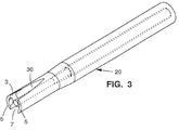
- FIG. 3 there is illustrated a first holder or probe 20 embodying the subject invention.
- the internal structure of this embodiment can be the same as in the probe 1 of Figure 1.
- the principal difference in the embodiment is the addition of a pair of opposed, axially extending open external channels 30. These channels are provided to further enhance the venting action discussed above. In this manner, vapor and debris which can damage the delivery end of the fiber 7 can be more effectively removed.
- the open external channels 30 can be used in combination with the vents 3 as shown in Figure 3. Alternatively, the channels 30 could be used alone. Depending upon the procedures used and the effectiveness of the venting system, it may not be necessary to space the delivery end of the fiber away from the target tissue.
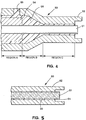
- the probe 50 includes a glass fiber 51 surrounded and supported by a stainless steel tubular support member 52.
- the glass fiber is typically surrounded by a buffer 54 formed from a material such as silicone.
- the buffer material is provided to strengthen the fiber which it allows it to be bent during damage.
- the buffer layer is relatively thick, on the order of 100 microns. Unfortunately, this material erodes rather quickly from debris and vapor during surgery. When this erosion occurs, the end of the fiber is free to move within the stainless steel support member and breaks down.
- the buffer material 54 is stripped away from the glass fiber in a region at the delivery end thereof.
- the buffer is stripped back a distance of about 0.64cm (0.25 inches).
- the inner diameter of the support 52 is then reduced so that the spacing between the outer circumferential surface of the fiber and the inner circumferential surface of the support member is very narrow. In the preferred embodiment this spacing is on the order of 0.0013 cm (0.0005 inches).
- an adhesive 56 is injected into the probe so that it fills or encapsulates the space between the fiber and the support member.
- the adhesive 56 is of the type which will not bend. Suitable adhesives are available and have been used to assemble probes. For example, we have used EPO-TEX 353 ND, epoxy resin manufactured by Epoxy Technology.
- the adhesive prevents the tip from being bent, the remainder of the probe can be bent during manufacturing to the desired angle.
- the elimination of flexibility in the tip should not prevent the assembly of probes with a variety of bend angles.
- the adhesive exists in three regions within the end of the probe.
- the-adhesive is injected into an area that extends somewhat into region A that is coated with the buffer.
- the overlap region will be about 0.64 cm (0.125 inches).
- the adhesive can be injected through a hole 58 provided in the support 52.
- the adhesive in region A because it fully fills the gap between the buffer and the support.
- the adhesive in region C also restrains the lateral movement of the fiber which is induced from either direct contact with the tissue being cut or forces created by the vaporization of water and tissue during each laser pulse.
- the encapsulation also prevents water and water vapor from penetrating into the fiber which reduces fiber strength.
- the support member 52 may extend beyond the delivery end of the fiber 51.
- the delivery end of the fiber 51 can be annealed. In the preferred embodiment, these features are incorporated in the probe.
- FIG. 5 An additional approach to reducing damage from erosion is shown in the probe 60 illustrated in Figure 5.
- the most rapid erosion occurs between the fiber 61 and the support member 62.
- the diameter of the end of the fiber 61 is enlarged to shield the area immediately behind the enlargement from debris and vapor.
- This enlargement can be produced in a variety of ways.
- the enlargement could be formed in the arc of a fiber fusion machine.
- a separate sleeve 64 of erosion resistant material, such as glass could be added to the fiber.
- This approach for reducing erosion can also be used in conjunction with the other approaches discussed above.
- a thin layer of adhesive 66 can be injected in the narrow space between an uncoated fiber and the support member62.
- support for the fiber tip at a predetermined distance from the target may be achieved using other housing materials and in many other ways.
- a gas stream having relatively high pressure through a concentric channel surrounding the fiber to provide both support for the fiber tip and a stream which would further inhibit the vapor and debris formed by the laser radiation from impacting the fiber tip.
Landscapes
- Health & Medical Sciences (AREA)
- Surgery (AREA)
- Physics & Mathematics (AREA)
- Life Sciences & Earth Sciences (AREA)
- Heart & Thoracic Surgery (AREA)
- Animal Behavior & Ethology (AREA)
- Nuclear Medicine, Radiotherapy & Molecular Imaging (AREA)
- Electromagnetism (AREA)
- Engineering & Computer Science (AREA)
- Biomedical Technology (AREA)
- Optics & Photonics (AREA)
- Medical Informatics (AREA)
- Molecular Biology (AREA)
- Otolaryngology (AREA)
- General Health & Medical Sciences (AREA)
- Public Health (AREA)
- Veterinary Medicine (AREA)
- Laser Surgery Devices (AREA)
- Light Guides In General And Applications Therefor (AREA)
- Optical Fibers, Optical Fiber Cores, And Optical Fiber Bundles (AREA)
- Radiation-Therapy Devices (AREA)
- Surgical Instruments (AREA)
Applications Claiming Priority (6)
| Application Number | Priority Date | Filing Date | Title |
|---|---|---|---|
| US47725690A | 1990-02-07 | 1990-02-07 | |
| US477256 | 1990-02-07 | ||
| US57786690A | 1990-09-04 | 1990-09-04 | |
| US577866 | 1990-09-04 | ||
| US58428790A | 1990-09-18 | 1990-09-18 | |
| US584287 | 1990-09-18 |
Publications (3)
| Publication Number | Publication Date |
|---|---|
| EP0441606A2 EP0441606A2 (en) | 1991-08-14 |
| EP0441606A3 EP0441606A3 (en) | 1992-01-08 |
| EP0441606B1 true EP0441606B1 (en) | 1996-09-25 |
Family
ID=27413411
Family Applications (1)
| Application Number | Title | Priority Date | Filing Date |
|---|---|---|---|
| EP91300960A Expired - Lifetime EP0441606B1 (en) | 1990-02-07 | 1991-02-06 | Contact laser delivery system |
Country Status (5)
| Country | Link |
|---|---|
| US (1) | US5300066A (ja) |
| EP (1) | EP0441606B1 (ja) |
| JP (1) | JP3285367B2 (ja) |
| DE (1) | DE69122279T2 (ja) |
| IL (1) | IL97130A (ja) |
Families Citing this family (42)
| Publication number | Priority date | Publication date | Assignee | Title |
|---|---|---|---|---|
| WO1993003678A1 (en) * | 1991-08-16 | 1993-03-04 | Myriadlase, Inc. | Laterally reflecting tip for laser transmitting fiber |
| US6406486B1 (en) | 1991-10-03 | 2002-06-18 | The General Hospital Corporation | Apparatus and method for vasodilation |
| WO1993006780A1 (en) * | 1991-10-03 | 1993-04-15 | The General Hospital Corporation | Apparatus and method for vasodilation |
| US5562658A (en) * | 1994-03-25 | 1996-10-08 | Snj Company, Inc. | Laser-powered surgical device for making incisions of selected depth |
| US5800165A (en) * | 1995-03-28 | 1998-09-01 | Loma Linda University Medical Center | Dental instrument and method of bleaching teeth using a laser |
| US5591161A (en) * | 1995-10-25 | 1997-01-07 | Plc Medical Systems, Inc. | Angled beam delivery handpiece for laser or other monochromatic light source |
| US5944687A (en) | 1996-04-24 | 1999-08-31 | The Regents Of The University Of California | Opto-acoustic transducer for medical applications |
| US6283955B1 (en) | 1996-05-13 | 2001-09-04 | Edwards Lifesciences Corp. | Laser ablation device |
| US5807383A (en) * | 1996-05-13 | 1998-09-15 | United States Surgical Corporation | Lasing device |
| US5947989A (en) * | 1996-12-12 | 1999-09-07 | United States Surgical Corporation | Method and apparatus for transmyocardial revascularization |
| US20010016732A1 (en) * | 1998-02-03 | 2001-08-23 | James L. Hobart | Dual mode laser delivery system providing controllable depth of tissue ablation and corresponding controllable depth of coagulation |
| US6575964B1 (en) | 1998-02-03 | 2003-06-10 | Sciton, Inc. | Selective aperture for laser delivery system for providing incision, tissue ablation and coagulation |
| US6135996A (en) * | 1998-04-17 | 2000-10-24 | Baxter International, Inc. | Controlled advancement lasing device |
| US6743221B1 (en) | 2001-03-13 | 2004-06-01 | James L. Hobart | Laser system and method for treatment of biological tissues |
| US6770069B1 (en) | 2001-06-22 | 2004-08-03 | Sciton, Inc. | Laser applicator |
| US9440046B2 (en) | 2002-04-04 | 2016-09-13 | Angiodynamics, Inc. | Venous insufficiency treatment method |
| US8864754B2 (en) * | 2002-07-10 | 2014-10-21 | Angiodynamics, Inc. | Device and method for endovascular treatment for causing closure of a blood vessel |
| DE10245140B4 (de) * | 2002-09-27 | 2005-10-20 | Dornier Medtech Laser Gmbh | Intelligente Therapiefaser |
| DE102005017798A1 (de) * | 2005-04-18 | 2006-11-09 | Dornier Medtech Laser Gmbh | Lichtleitfaser |
| US20070049911A1 (en) * | 2005-08-26 | 2007-03-01 | Brown Joe D | Endovascular method and apparatus with feedback |
| EP1803454A1 (en) * | 2005-12-30 | 2007-07-04 | Dornier MedTech Laser GmbH | Treatment of cancer by a combination of non-ionizing radiation and androgen deprivation |
| EP1914576B1 (de) * | 2006-10-17 | 2019-01-16 | Dornier MedTech Laser GmbH | Laserapplikator mit einem einen photorefraktiven Bereich mit Volumenhologramm umfassenden Lichtleiter. |
| FR2913192B1 (fr) * | 2007-03-02 | 2010-02-26 | Optical System & Res For Ind & Science Osyris | Ensemble canule/fibre optique et instrument laser comportant ledit ensemble. |
| US20090177191A1 (en) * | 2007-12-11 | 2009-07-09 | Brown Joe D | Laser surgery methods and apparatus |
| ES2710180T3 (es) | 2008-04-25 | 2019-04-23 | Dornier Medtech Laser Gmbh | Dispositivo basado en luz para el tratamiento endovascular de vasos sanguíneos patológicamente alterados |
| US9345543B2 (en) * | 2008-07-02 | 2016-05-24 | Joe Denton Brown | Laser delivery apparatus for endovascular applications |
| WO2010053575A2 (en) * | 2008-11-07 | 2010-05-14 | Joe Denton Brown | Apparatus and method for detecting overheating during laser surgery |
| US9314303B2 (en) * | 2010-03-23 | 2016-04-19 | Joe Denton Brown | Laser surgery controller with variable time delay and feedback detector sensitivity control |
| US8638428B2 (en) | 2010-06-01 | 2014-01-28 | Joe Denton Brown | Method and apparatus for using optical feedback to detect fiber breakdown during surgical laser procedures |
| FR2963685A1 (fr) * | 2010-08-06 | 2012-02-10 | Carrier Kheops Bac | Passage d'un ruban de fibres optiques |
| US9763735B2 (en) | 2011-02-24 | 2017-09-19 | Eximo Medical Ltd. | Hybrid catheter for endoluminal intervention |
| US8992513B2 (en) | 2011-06-30 | 2015-03-31 | Angiodynamics, Inc | Endovascular plasma treatment device and method of use |
| US12514456B2 (en) | 2013-01-31 | 2026-01-06 | Eximo Medical Ltd. | System and methods for lesion characterization in blood vessels |
| US10324037B2 (en) * | 2013-11-13 | 2019-06-18 | Gustav Hudson | Low energy laser spectroscopy LELS |
| EP3791817B1 (en) | 2014-10-01 | 2024-05-22 | Medtronic Ardian Luxembourg S.à.r.l. | Systems for evaluating neuromodulation therapy via hemodynamic responses |
| JP6463218B2 (ja) * | 2015-05-15 | 2019-01-30 | アンリツ株式会社 | レーザ治療装置および食道癌用光線力学的治療装置 |
| JP6366040B2 (ja) * | 2015-06-03 | 2018-08-01 | 株式会社Smmプレシジョン | ピグテールファイバモジュール |
| US11684420B2 (en) | 2016-05-05 | 2023-06-27 | Eximo Medical Ltd. | Apparatus and methods for resecting and/or ablating an undesired tissue |
| US11278352B2 (en) * | 2016-05-05 | 2022-03-22 | Optical Integrity, Inc. | Protective caps of tips for surgical laser fibers |
| US10561407B2 (en) * | 2017-05-05 | 2020-02-18 | Hoya Corporation | Apparatuses and methods for endoscopic tool joints |
| US12376904B1 (en) | 2020-09-08 | 2025-08-05 | Angiodynamics, Inc. | Dynamic laser stabilization and calibration system |
| US12038322B2 (en) | 2022-06-21 | 2024-07-16 | Eximo Medical Ltd. | Devices and methods for testing ablation systems |
Citations (1)
| Publication number | Priority date | Publication date | Assignee | Title |
|---|---|---|---|---|
| US4660925A (en) * | 1985-04-29 | 1987-04-28 | Laser Therapeutics, Inc. | Apparatus for producing a cylindrical pattern of light and method of manufacture |
Family Cites Families (15)
| Publication number | Priority date | Publication date | Assignee | Title |
|---|---|---|---|---|
| US3693623A (en) * | 1970-12-25 | 1972-09-26 | Gregory System Inc | Photocoagulation means and method for depilation |
| DE2145921C2 (de) * | 1971-09-14 | 1982-05-06 | Günther Dr. 8022 Grünwald Nath | Einrichtung zur Materialbearbeitung durch ein Laserstrahlungsbündel mit einem biegsamen Lichtleiter |
| JPS5552750A (en) * | 1978-10-12 | 1980-04-17 | Mochida Pharm Co Ltd | Laser knife* which can be detected* of tumor portion |
| DE2853528C2 (de) * | 1978-12-12 | 1983-04-07 | Messerschmitt-Bölkow-Blohm GmbH, 8000 München | Flexibler Lichtleiter für Laser-Anwendungen |
| JPS589111U (ja) * | 1981-07-07 | 1983-01-21 | 住友電気工業株式会社 | レ−ザメス |
| JPS6041928Y2 (ja) * | 1981-09-04 | 1985-12-21 | 株式会社モリタ製作所 | レ−ザ光による歯科処置用コントラアングル型ハンドピ−ス |
| US4519390A (en) * | 1982-10-15 | 1985-05-28 | Hgm, Inc. | Fiber optic laser catheter |
| US4576177A (en) * | 1983-02-18 | 1986-03-18 | Webster Wilton W Jr | Catheter for removing arteriosclerotic plaque |
| GB8428411D0 (en) * | 1984-11-09 | 1984-12-19 | Micra Ltd | Laser knives |
| US4830460A (en) * | 1987-05-19 | 1989-05-16 | Advanced Interventional Systems, Inc. | Guidance system and method for delivery system for high-energy pulsed ultraviolet laser light |
| US4917084A (en) * | 1985-07-31 | 1990-04-17 | C. R. Bard, Inc. | Infrared laser catheter system |
| US4819630A (en) * | 1987-03-20 | 1989-04-11 | Laser Photonics, Inc. | Flexible light transmissive apparatus and method |
| US4803460A (en) * | 1987-05-18 | 1989-02-07 | Ford Motor Company | Anti-theft system |
| US4812001A (en) * | 1987-07-28 | 1989-03-14 | Raychem Corp. | Annealing bent optical fiber |
| DE8904568U1 (de) * | 1989-04-11 | 1989-06-29 | Aesculap AG, 7200 Tuttlingen | Medizinisches Handstück, insbesondere für die Dentalmedizin |
-
1991
- 1991-02-01 IL IL9713091A patent/IL97130A/en not_active IP Right Cessation
- 1991-02-06 EP EP91300960A patent/EP0441606B1/en not_active Expired - Lifetime
- 1991-02-06 DE DE69122279T patent/DE69122279T2/de not_active Expired - Fee Related
- 1991-02-07 JP JP03804791A patent/JP3285367B2/ja not_active Expired - Fee Related
-
1992
- 1992-06-23 US US07/905,125 patent/US5300066A/en not_active Expired - Lifetime
Patent Citations (1)
| Publication number | Priority date | Publication date | Assignee | Title |
|---|---|---|---|---|
| US4660925A (en) * | 1985-04-29 | 1987-04-28 | Laser Therapeutics, Inc. | Apparatus for producing a cylindrical pattern of light and method of manufacture |
Also Published As
| Publication number | Publication date |
|---|---|
| JP3285367B2 (ja) | 2002-05-27 |
| DE69122279T2 (de) | 1997-02-06 |
| IL97130A0 (en) | 1992-05-25 |
| EP0441606A3 (en) | 1992-01-08 |
| US5300066A (en) | 1994-04-05 |
| DE69122279D1 (de) | 1996-10-31 |
| IL97130A (en) | 1995-07-31 |
| EP0441606A2 (en) | 1991-08-14 |
| JPH04215749A (ja) | 1992-08-06 |
Similar Documents
| Publication | Publication Date | Title |
|---|---|---|
| EP0441606A2 (en) | Contact laser delivery system | |
| US20240315774A1 (en) | Systems, Devices, and Related Methods for Laser Lithotripsy | |
| EP0634947B1 (en) | Apparatus for performing eye surgery | |
| US5425735A (en) | Shielded tip catheter for lithotripsy | |
| US5032123A (en) | Laser catheter with radially divergent treatment beam | |
| US5061265A (en) | Laser treatment apparatus and method | |
| EP0214712B1 (en) | Infrared laser catheter apparatus | |
| US4686979A (en) | Excimer laser phototherapy for the dissolution of abnormal growth | |
| EP3597133B1 (en) | Side-fire laser fiber having a molded reflective surface | |
| US20090163899A1 (en) | Swaged optical fiber catheter tips and methods of making and using | |
| EP3454718A1 (en) | Protective caps or tips for surgical laser fibers | |
| US20230101488A1 (en) | Surgical laser fiber with reflective standoff sleeve and method of preventing dust particle buildup within a standoff sleeve | |
| US5257989A (en) | Contact laser delivery probe | |
| US5407443A (en) | Laser operation device | |
| WO1996018347A1 (en) | Optical fibre laser delivery probe and use thereof | |
| WO1993011711A1 (en) | Shielded tip catheter | |
| EP3784158B1 (en) | Medical optical fiber with protective tip and method of manufacture therefor | |
| Rol et al. | High-Power Laser Transmission through Optical Fibers Applications to Ophthalmology | |
| JPS5997110A (ja) | 光フアイバ用コネクタ | |
| JPH07148196A (ja) | レーザー手術装置 | |
| AU699994B2 (en) | Apparatus and method for performing eye surgery | |
| JPS5997109A (ja) | 光フアイバ用コネクタ | |
| JPH06105863A (ja) | 眼内手術装置 |
Legal Events
| Date | Code | Title | Description |
|---|---|---|---|
| PUAI | Public reference made under article 153(3) epc to a published international application that has entered the european phase |
Free format text: ORIGINAL CODE: 0009012 |
|
| AK | Designated contracting states |
Kind code of ref document: A2 Designated state(s): CH DE FR GB IT LI |
|
| PUAL | Search report despatched |
Free format text: ORIGINAL CODE: 0009013 |
|
| AK | Designated contracting states |
Kind code of ref document: A3 Designated state(s): CH DE FR GB IT LI |
|
| 17P | Request for examination filed |
Effective date: 19920625 |
|
| 17Q | First examination report despatched |
Effective date: 19940707 |
|
| RAP1 | Party data changed (applicant data changed or rights of an application transferred) |
Owner name: COHERENT, INC. |
|
| GRAH | Despatch of communication of intention to grant a patent |
Free format text: ORIGINAL CODE: EPIDOS IGRA |
|
| GRAH | Despatch of communication of intention to grant a patent |
Free format text: ORIGINAL CODE: EPIDOS IGRA |
|
| GRAA | (expected) grant |
Free format text: ORIGINAL CODE: 0009210 |
|
| AK | Designated contracting states |
Kind code of ref document: B1 Designated state(s): CH DE FR GB IT LI |
|
| PG25 | Lapsed in a contracting state [announced via postgrant information from national office to epo] |
Ref country code: IT Free format text: LAPSE BECAUSE OF FAILURE TO SUBMIT A TRANSLATION OF THE DESCRIPTION OR TO PAY THE FEE WITHIN THE PRE;WARNING: LAPSES OF ITALIAN PATENTS WITH EFFECTIVE DATE BEFORE 2007 MAY HAVE OCCURRED AT ANY TIME BEFORE 2007. THE CORRECT EFFECTIVE DATE MAY BE DIFFERENT FROM THE ONE RECORDED.SCRIBED TIME-LIMIT Effective date: 19960925 |
|
| REG | Reference to a national code |
Ref country code: CH Ref legal event code: NV Representative=s name: BOVARD AG PATENTANWAELTE |
|
| REF | Corresponds to: |
Ref document number: 69122279 Country of ref document: DE Date of ref document: 19961031 |
|
| ET | Fr: translation filed | ||
| PGFP | Annual fee paid to national office [announced via postgrant information from national office to epo] |
Ref country code: CH Payment date: 19970220 Year of fee payment: 7 |
|
| PLBE | No opposition filed within time limit |
Free format text: ORIGINAL CODE: 0009261 |
|
| STAA | Information on the status of an ep patent application or granted ep patent |
Free format text: STATUS: NO OPPOSITION FILED WITHIN TIME LIMIT |
|
| 26N | No opposition filed | ||
| PG25 | Lapsed in a contracting state [announced via postgrant information from national office to epo] |
Ref country code: LI Free format text: LAPSE BECAUSE OF NON-PAYMENT OF DUE FEES Effective date: 19980228 Ref country code: CH Free format text: LAPSE BECAUSE OF NON-PAYMENT OF DUE FEES Effective date: 19980228 |
|
| REG | Reference to a national code |
Ref country code: CH Ref legal event code: PL |
|
| REG | Reference to a national code |
Ref country code: GB Ref legal event code: 732E |
|
| REG | Reference to a national code |
Ref country code: GB Ref legal event code: IF02 |
|
| PGFP | Annual fee paid to national office [announced via postgrant information from national office to epo] |
Ref country code: GB Payment date: 20020125 Year of fee payment: 12 |
|
| PGFP | Annual fee paid to national office [announced via postgrant information from national office to epo] |
Ref country code: DE Payment date: 20020212 Year of fee payment: 12 |
|
| PGFP | Annual fee paid to national office [announced via postgrant information from national office to epo] |
Ref country code: FR Payment date: 20020227 Year of fee payment: 12 |
|
| PG25 | Lapsed in a contracting state [announced via postgrant information from national office to epo] |
Ref country code: GB Free format text: LAPSE BECAUSE OF NON-PAYMENT OF DUE FEES Effective date: 20030206 |
|
| PG25 | Lapsed in a contracting state [announced via postgrant information from national office to epo] |
Ref country code: DE Free format text: LAPSE BECAUSE OF NON-PAYMENT OF DUE FEES Effective date: 20030902 |
|
| GBPC | Gb: european patent ceased through non-payment of renewal fee | ||
| PG25 | Lapsed in a contracting state [announced via postgrant information from national office to epo] |
Ref country code: FR Free format text: LAPSE BECAUSE OF NON-PAYMENT OF DUE FEES Effective date: 20031031 |
|
| REG | Reference to a national code |
Ref country code: FR Ref legal event code: ST |