EP0441618B1 - Boîte d'emballage - Google Patents
Boîte d'emballage Download PDFInfo
- Publication number
- EP0441618B1 EP0441618B1 EP91300984A EP91300984A EP0441618B1 EP 0441618 B1 EP0441618 B1 EP 0441618B1 EP 91300984 A EP91300984 A EP 91300984A EP 91300984 A EP91300984 A EP 91300984A EP 0441618 B1 EP0441618 B1 EP 0441618B1
- Authority
- EP
- European Patent Office
- Prior art keywords
- structural unit
- barrel
- packing
- boundary
- unit faces
- Prior art date
- Legal status (The legal status is an assumption and is not a legal conclusion. Google has not performed a legal analysis and makes no representation as to the accuracy of the status listed.)
- Expired - Lifetime
Links
Images





Classifications
-
- B—PERFORMING OPERATIONS; TRANSPORTING
- B65—CONVEYING; PACKING; STORING; HANDLING THIN OR FILAMENTARY MATERIAL
- B65D—CONTAINERS FOR STORAGE OR TRANSPORT OF ARTICLES OR MATERIALS, e.g. BAGS, BARRELS, BOTTLES, BOXES, CANS, CARTONS, CRATES, DRUMS, JARS, TANKS, HOPPERS, FORWARDING CONTAINERS; ACCESSORIES, CLOSURES, OR FITTINGS THEREFOR; PACKAGING ELEMENTS; PACKAGES
- B65D1/00—Rigid or semi-rigid containers having bodies formed in one piece, e.g. by casting metallic material, by moulding plastics, by blowing vitreous material, by throwing ceramic material, by moulding pulped fibrous material or by deep-drawing operations performed on sheet material
- B65D1/12—Cans, casks, barrels, or drums
- B65D1/14—Cans, casks, barrels, or drums characterised by shape
-
- B—PERFORMING OPERATIONS; TRANSPORTING
- B65—CONVEYING; PACKING; STORING; HANDLING THIN OR FILAMENTARY MATERIAL
- B65D—CONTAINERS FOR STORAGE OR TRANSPORT OF ARTICLES OR MATERIALS, e.g. BAGS, BARRELS, BOTTLES, BOXES, CANS, CARTONS, CRATES, DRUMS, JARS, TANKS, HOPPERS, FORWARDING CONTAINERS; ACCESSORIES, CLOSURES, OR FITTINGS THEREFOR; PACKAGING ELEMENTS; PACKAGES
- B65D7/00—Containers having bodies formed by interconnecting or uniting two or more rigid, or substantially rigid, components made wholly or mainly of metal
- B65D7/42—Details of metal walls
- B65D7/44—Reinforcing or strengthening parts or members
- B65D7/46—Corrugations
-
- B—PERFORMING OPERATIONS; TRANSPORTING
- B21—MECHANICAL METAL-WORKING WITHOUT ESSENTIALLY REMOVING MATERIAL; PUNCHING METAL
- B21D—WORKING OR PROCESSING OF SHEET METAL OR METAL TUBES, RODS OR PROFILES WITHOUT ESSENTIALLY REMOVING MATERIAL; PUNCHING METAL
- B21D51/00—Making hollow objects
- B21D51/16—Making hollow objects characterised by the use of the objects
- B21D51/26—Making hollow objects characterised by the use of the objects cans or tins; Closing same in a permanent manner
- B21D51/2646—Of particular non cylindrical shape, e.g. conical, rectangular, polygonal, bulged
-
- B—PERFORMING OPERATIONS; TRANSPORTING
- B29—WORKING OF PLASTICS; WORKING OF SUBSTANCES IN A PLASTIC STATE IN GENERAL
- B29C—SHAPING OR JOINING OF PLASTICS; SHAPING OF MATERIAL IN A PLASTIC STATE, NOT OTHERWISE PROVIDED FOR; AFTER-TREATMENT OF THE SHAPED PRODUCTS, e.g. REPAIRING
- B29C51/00—Shaping by thermoforming, i.e. shaping sheets or sheet like preforms after heating, e.g. shaping sheets in matched moulds or by deep-drawing; Apparatus therefor
- B29C51/08—Deep drawing or matched-mould forming, i.e. using mechanical means only
- B29C51/082—Deep drawing or matched-mould forming, i.e. using mechanical means only by shaping between complementary mould parts
- B29C51/085—Deep drawing or matched-mould forming, i.e. using mechanical means only by shaping between complementary mould parts with at least one of the shaping surfaces being made of resilien material, e.g. rubber
-
- B—PERFORMING OPERATIONS; TRANSPORTING
- B29—WORKING OF PLASTICS; WORKING OF SUBSTANCES IN A PLASTIC STATE IN GENERAL
- B29C—SHAPING OR JOINING OF PLASTICS; SHAPING OF MATERIAL IN A PLASTIC STATE, NOT OTHERWISE PROVIDED FOR; AFTER-TREATMENT OF THE SHAPED PRODUCTS, e.g. REPAIRING
- B29C51/00—Shaping by thermoforming, i.e. shaping sheets or sheet like preforms after heating, e.g. shaping sheets in matched moulds or by deep-drawing; Apparatus therefor
- B29C51/18—Thermoforming apparatus
- B29C51/20—Thermoforming apparatus having movable moulds or mould parts
- B29C51/22—Thermoforming apparatus having movable moulds or mould parts rotatable about an axis
-
- B—PERFORMING OPERATIONS; TRANSPORTING
- B29—WORKING OF PLASTICS; WORKING OF SUBSTANCES IN A PLASTIC STATE IN GENERAL
- B29C—SHAPING OR JOINING OF PLASTICS; SHAPING OF MATERIAL IN A PLASTIC STATE, NOT OTHERWISE PROVIDED FOR; AFTER-TREATMENT OF THE SHAPED PRODUCTS, e.g. REPAIRING
- B29C53/00—Shaping by bending, folding, twisting, straightening or flattening; Apparatus therefor
- B29C53/22—Corrugating
- B29C53/30—Corrugating of tubes
-
- B—PERFORMING OPERATIONS; TRANSPORTING
- B29—WORKING OF PLASTICS; WORKING OF SUBSTANCES IN A PLASTIC STATE IN GENERAL
- B29C—SHAPING OR JOINING OF PLASTICS; SHAPING OF MATERIAL IN A PLASTIC STATE, NOT OTHERWISE PROVIDED FOR; AFTER-TREATMENT OF THE SHAPED PRODUCTS, e.g. REPAIRING
- B29C59/00—Surface shaping of articles, e.g. embossing; Apparatus therefor
- B29C59/02—Surface shaping of articles, e.g. embossing; Apparatus therefor by mechanical means, e.g. pressing
- B29C59/022—Surface shaping of articles, e.g. embossing; Apparatus therefor by mechanical means, e.g. pressing characterised by the disposition or the configuration, e.g. dimensions, of the embossments or the shaping tools therefor
-
- B—PERFORMING OPERATIONS; TRANSPORTING
- B29—WORKING OF PLASTICS; WORKING OF SUBSTANCES IN A PLASTIC STATE IN GENERAL
- B29C—SHAPING OR JOINING OF PLASTICS; SHAPING OF MATERIAL IN A PLASTIC STATE, NOT OTHERWISE PROVIDED FOR; AFTER-TREATMENT OF THE SHAPED PRODUCTS, e.g. REPAIRING
- B29C67/00—Shaping techniques not covered by groups B29C39/00 - B29C65/00, B29C70/00 or B29C73/00
- B29C67/0014—Shaping techniques not covered by groups B29C39/00 - B29C65/00, B29C70/00 or B29C73/00 for shaping tubes or blown tubular films
-
- B—PERFORMING OPERATIONS; TRANSPORTING
- B29—WORKING OF PLASTICS; WORKING OF SUBSTANCES IN A PLASTIC STATE IN GENERAL
- B29C—SHAPING OR JOINING OF PLASTICS; SHAPING OF MATERIAL IN A PLASTIC STATE, NOT OTHERWISE PROVIDED FOR; AFTER-TREATMENT OF THE SHAPED PRODUCTS, e.g. REPAIRING
- B29C59/00—Surface shaping of articles, e.g. embossing; Apparatus therefor
- B29C59/02—Surface shaping of articles, e.g. embossing; Apparatus therefor by mechanical means, e.g. pressing
- B29C59/04—Surface shaping of articles, e.g. embossing; Apparatus therefor by mechanical means, e.g. pressing using rollers or endless belts
-
- B—PERFORMING OPERATIONS; TRANSPORTING
- B29—WORKING OF PLASTICS; WORKING OF SUBSTANCES IN A PLASTIC STATE IN GENERAL
- B29K—INDEXING SCHEME ASSOCIATED WITH SUBCLASSES B29B, B29C OR B29D, RELATING TO MOULDING MATERIALS OR TO MATERIALS FOR MOULDS, REINFORCEMENTS, FILLERS OR PREFORMED PARTS, e.g. INSERTS
- B29K2705/00—Use of metals, their alloys or their compounds, for preformed parts, e.g. for inserts
-
- B—PERFORMING OPERATIONS; TRANSPORTING
- B29—WORKING OF PLASTICS; WORKING OF SUBSTANCES IN A PLASTIC STATE IN GENERAL
- B29L—INDEXING SCHEME ASSOCIATED WITH SUBCLASS B29C, RELATING TO PARTICULAR ARTICLES
- B29L2009/00—Layered products
-
- B—PERFORMING OPERATIONS; TRANSPORTING
- B29—WORKING OF PLASTICS; WORKING OF SUBSTANCES IN A PLASTIC STATE IN GENERAL
- B29L—INDEXING SCHEME ASSOCIATED WITH SUBCLASS B29C, RELATING TO PARTICULAR ARTICLES
- B29L2023/00—Tubular articles
-
- B—PERFORMING OPERATIONS; TRANSPORTING
- B29—WORKING OF PLASTICS; WORKING OF SUBSTANCES IN A PLASTIC STATE IN GENERAL
- B29L—INDEXING SCHEME ASSOCIATED WITH SUBCLASS B29C, RELATING TO PARTICULAR ARTICLES
- B29L2031/00—Other particular articles
- B29L2031/712—Containers; Packaging elements or accessories, Packages
-
- B—PERFORMING OPERATIONS; TRANSPORTING
- B29—WORKING OF PLASTICS; WORKING OF SUBSTANCES IN A PLASTIC STATE IN GENERAL
- B29L—INDEXING SCHEME ASSOCIATED WITH SUBCLASS B29C, RELATING TO PARTICULAR ARTICLES
- B29L2031/00—Other particular articles
- B29L2031/712—Containers; Packaging elements or accessories, Packages
- B29L2031/717—Cans, tins
Definitions
- the present invention relates to a packing can. More particularly, the present invention relates to a packing can which has excellent resistance to deformation by pressure reduction at the cooling step after or during subsequent storage, and in which it is made possible to reduce the thickness of the blank to be used.
- Metal is mainly used for a packing can but sometimes, a resin material is used.
- a so-called three-piece can is prepared by forming metal sheet into a cylindrical shape, joining confronting edge portions by welding, bonding or soldering to form a can barrel having a side seam and wrap-seaming both the ends of the can barrel with top and bottom lids.
- a so-called two-piece can is formed by deep-drawing or further ironing the metal sheet into a bottomed can barrel and wrap-seaming the top end of the bottomed can barrel with a lid.
- the above-mentioned deformation is considerably reduced, but where circumferential beads are formed on the front face of the can barrel member, the increase of the deformation load by the external pressure (the increase of the strength against the deformation by the external pressure) is about 2 times at highest, as compared with the case of a similar can having no beads formed. Accordingly, even if the thickness of the blank is considerably reduced, the object of completely preventing deformation by reduction of the pressure is not sufficiently attained.
- DE 2 944 134 describes a container with dimpled sides.
- the container is cylindrical and at least a portion of the cylindrical wall is a circumferential polyhedral wall having a plurality of structural unit faces. There are boundary ridge lines where the structural units touch and crossing portions where the ridge lines cross.
- the structural unit faces are convex to the interior of the can.
- the structural unit spacers are arranged in a plurality of rows in both the circumferential and axial directions. Adjacent rows in the axial direction have a phase difference.
- the maximum length L in the axial direction and the width W in the circumferential direction satisfy the requirement 1.25 ⁇ L/W ⁇ 3.33.
- a cylindrical packing can having a resistance against deformation by external pressure, comprising a cylindrical can wall having at least a portion thereof formed as a circumferential polyhedral wall having a plurality of structural unit faces, boundary ridgelines where the structural units touch each other, and crossing portions where the boundary ridgelines cross each other, wherein as compared with the boundary ridgelines and crossing portions, the structural unit faces are convex to the interior of the can, the structural unit faces are arranged in a plurality of rows in both the circumferential direction and the axial direction of the can so that the adjacent rows of the structural unit faces have a phase difference in the axial direction of the can, the maximum length L of the structural unit face in the axial direction of the can and the width W of the structural unit face in the circumferential direction satisfy the requirement of 0.2 ⁇ L/W ⁇ 4, characterized in that the number of the structural unit faces present on the same phase relatively to the axial direction of the can per circle of the can barrel is in the range of from 3 to 14, and that
- Fig. 1 is a graph showing the relation between the empty can external pressure resistance ratio (the ratio of the external pressure resistance in the case where a circumferential polyhedral wall is formed to the exterior pressure resistance in the case where no circumferential polyhedral wall is formed) and the number n of the structural unit faces of the circumferential polyhedral wall per circle of the can barrel.
- Fig. 2-A is a side view of the packing can of the present invention in which a circumferential polyhedral wall having tetragonal structural unit faces is formed on the can barrel
- Fig. 2-B is a longitudinally sectional view of this packing can
- Fig. 2-C is a horizontally sectional view of this packing can.
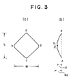
- Figs. 3(a) and 3(b) are plane and sectional views showing an example of the structural unit face of the circumferential polyhedral wall formed on the can barrel of the packing can of the present invention.
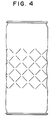
- Fig. 4 is a side view of a packing can where the circumferential polyhedral wall shown in Fig. 2 is formed only at the central part of the can barrel.
- Fig. 5 is a graph illustrating the relation between the L/W value (in which L represents the maximum length of the structural unit face in the axial direction of the can and W represents the maximum width of the structural unit face in the circumferential direction) of the circumferential polyhedral wall formed on the can barrel and the empty can external pressure resistance.
- Fig. 6 is a graph illustrating the relation between the depth ratio of the structural unit face and the empty can strength against the outer pressure.
- Fig. 7 is a diagram illustrating a structural unit face having an equilateral triangular shape.
- Figs. 8-A and 8-B are side and longitudinally sectional views of a packing can in which a circumferential polyhedral wall having structural unit faces as shown in Fig. 7 is formed on the can barrel.
- Fig. 9 is a side view of a packing can in which circumferential polyhedral wall having structural unit faces having a shape different from the shape shown in Fig. 7 is formed on the can barrel.
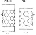
- Fig. 10 is a side view illustrating a packing can in which a circumferential polyhedral wall having structural unit faces having a hexagonal shape is formed on the can barrel
- Fig. 11 is an enlarged view illustrating a part of the packing can shown in Fig. 10.
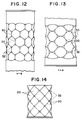
- Fig. 12 is a side view illustrating a packing can in which a circumferential polyhedral wall having structural unit faces having a hexagonal shape having a curvature is formed on the can barrel
- Fig. 13 is an enlarged view illustrating a part of the packing can shown in Fig. 12.
- Fig. 14 is a side view illustrating a part of a packing can in which a circumferential polyhedral wall having structural unit faces having a tetragonal shape having a curvature is formed on the can barrel.
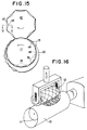
- Figs. 15 and 16 are diagrams illustrating processes for forming a polyhedron on the can barrel.
- Figs. 17 and 18 are enlarged sectional views showing partially outer molds used for forming a polyhedron.
- Fig. 19 is a diagram illustrating another process for forming a polyhedron on the can barrel.
- the packing can of the present invention has a circumferential polyhedral wall formed on the can barrel, and as compared with boundary ridgelines of structural unit faces of the polyhedral wall and points of crossing of the boundary ridgelines, the structural unit faces are convex to the interior of the can, and the structural unit faces are arranged so that the adjacent rows of the structural unit faces have a phase difference, especially a phase difference of 1/2, in the axial direction of the can.
- This circumferential polyhedral wall need not be formed on the entire surface of the can barrel, but if the circumferential polyhedral wall is forced on a part of the can barrel, for example, on an area of at least 10% of the entire surface of the can barrel, a sufficient resistance can be attained. It is especially preferred that the circumferential polyhedral wall be formed at a central part of the can barrel.
- the above-mentioned circumferential polyhedral wall can be formed at any part of the can barrel, and can be easily formed at a plurality of parts of the can barrel.
- the number of the structural unit faces of the circumferential polyhedral wall present per circle of the can barrel is a factor important for imparting an excellent deformation resistance to the can.
- the number n of the structural unit faces present on the same phase relatively to the axial direction of the can per circle of the can barrel is from 3 to 14, though the preferred number n differs to some extent according to the shape of the structural unit faces. Especially in case of tetragonal structural unit faces, it is preferred that the number n be from 4 to 12, and in case of hexagonal structural unit faces, it is preferred that the number n be from 3 to 10.
- the empty can external pressure resistance ratio between a can having a circumferential polyhedral wall of structural unit faces of an equilateral triangular shape formed on the can barrel and a can having no circumferential polyhedral wall formed on the can barrel is plotted to the number n of the structural unit faces in Fig. 1. From Fig. 1, is seen that with increase of the number n, the empty can external pressure resistance ratio lowers, and if the number n exceeds 14, no improvement of the empty can external pressure resistance ratio is attained. If the number n is smaller than 3, a sufficient circumferential polyhedral wall cannot be formed on the can barrel, and furthermore, since bending is sharp on the can barrel surface, the corrosion resistance of the coating is drastically degraded and the appearance becomes bad.
- each structural unit face is curved toward the inner side of the can or appears as a V-shaped dent.
- the sectional side face of the can barrel appears as a straight line in the axial direction of the can.
- the structural unit faces in the above-mentioned manner and arranging these structural unit faces so that the adjacent rows of the structural unit faces have a phase difference, especially a phase difference of 1/2, in the axial direction of the can, a deformation resistance is given to the can barrel.
- this arrangement of the structural unit faces it is possible to form the circumferential polyhedral wall so that the surface area of the can barrel before the formation of the circumferential polyhedral wall is substantially equal to the surface area of the can barrel after the formation of the circumferential polyhedral wall. Therefore, the coating film is not damaged and an excellent corrosion resistance is maintained, and the stress left after the working is small and reduction of the adhesion of the coating and the bonding force of the seam during or after retort sterilization can be effectively prevented.
- the shape of the structural unit faces constituting the circumferential polyhedral wall is not particularly critical, so long as the circumferential polyhedral wall having a structure mentioned above is formed on the can barrel.
- the structural unit faces may have a tetragonal or hexagonal shape, or a polygonal shape having rounded corners, that is, a shape close to a circular shape.
- a tetragonal shape is especially preferable for imparting an excellent deformation resistance to the can barrel.
- FIG. 3(a) is a plane view of the structural unit face
- Fig. 3(b) is a sectional side view thereof.
- the structural unit face has a rhombic shape abcd, and each of sides ab, bc, cd and da is a boundary ridgeline formed on the side face of the can.
- the crossing points of these boundary ridgelines are apexes, a, b, c and d convex to the outside.
- the line portion connecting b and d is gently curved, and the structural unit face is convex to the interior of the can.
- Fig. 2-C showing the horizontal section of the can shown in Fig. 2-A
- the respective apexes a through d of the rhombic structural unit face most project substantially in the radial direction and they are located on the circle having radius r from the center O of the can barrel.
- the central point (middle point between b and d) of the rhombic structural unit face is located on the most inner side in the radial direction.
- the surface area of the can barrel before the formation of the polyhedral wall is kept substantially equal to the surface area of the can barrel after the formation of the polyhedral wall, and damage of the coating film and cracking of the surface treatment layer can be effectively prevented, as described above.
- the trough formed in the central portion of the structural unit face is a smooth curved portion, and a design can be formed on the trough with a good reproducibility to impart a beautiful appearance and as in case of the conventional cylindrical can, the content is easily removed from the vessel.
- Figs. 2-A and Fig. 4 which are side views showing a can in which rhombic structural unit faces are formed on the can barrel, the structural faces are arranged in rows in either the circumferential direction or the axial direction so that adjacent rows of the structural unit faces have a phase difference of 1/2 in the axial direction.
- the boundary ridgelines of the structural unit faces should not extend along the axial direction of the can (the vertical direction in the drawings). If this arrangement of the structural unit faces is adopted, the strength against deformation of the can barrel by the external pressure is unexpectedly improved. It is considered that this effect is probably attained because the rhombic structural unit faces are built in the wall of the can barrel firmly and integrally with one another, though the mechanism has not been elucidated.
- W representing the length bc is the maximum width of the structural unit face and L representing the height ac is the maximum length in the axial direction.
- L representing the height ac is the maximum length in the axial direction.
- the relation of 0.2 ⁇ L/W ⁇ 4 is established between W and L.
- Fig. 5 illustrating the relation between this L/W value and the empty can external pressure resistance ratio, if the L/W value exceeds the above range, the intended effect of improving the empty can external pressure resistance ratio tends to lower, though there arises no substantial problem about the appearance.
- L/W is too small and below the above range, although the empty can external pressure resistance ratio is good, the can barrel per se is readily deformed by the axial compression, and the appearance is degraded and, for example, the quality of a printed image formed on the surface of the can is degraded.
- This relation between L/W and the empty can external pressure resistance ratio is similarly established in the structural unit face having a hexagonal shape or other shape, as well as in the structural unit face having a tetragonal shape such as a rhombic shape.
- the depth quantity d of the central portion of the structural unit face (the quantity of the concavity from the straight circumferential face of the can barrel at a part where the structural unit face is not formed) also is a factor important for obtaining a sufficient external pressure resistance. Supposing that the radius of the can barrel is r, the crossing points a through d of the structural unit face are located on this radius, though there are produced errors by reason of molding.
- the value do has a close relation to the maximum width W of the structural unit face, and W has a relation to the maximum length L in the axial direction. Consequently, the depth quantity d has a close relation to both of W and L and the allowance range of the depth quantity d is changed according to W and L.
- do is represented by the formula of 1/2 ⁇ w[sin( ⁇ /n)] -1 ⁇ [1-cos( ⁇ /n)] , and it is understood that do is determined by the maximum width W and the number n of the structural unit faces present in the circumferential direction. Accordingly, in view of the above-mentioned preferred range of the depth ratio d/do, it is understood that the preferred value of the depth quantity d increases as W increases and the preferred value of d/do decreases as in increases.
- a complete fold can be formed in the central portion of the rhombic structural unit face shown in Figs. 3(a) and 3(b) to form minimum structural unit faces having a shape of an equilateral triangle.
- This structural unit face is shown in Figs. 7(A) and 7(B), and a can having the circumferential polyhedral wall comprising these structural unit faces is shown in Figs. 8-A and 8-B.
- the section of the structural unit face has a V-shape, and as shown in Fig.
- the equilateral triangle ABC forms a minimum structural face unit (basic structural face unit), and each of sides AB, BC and CA of the equilateral triangle is commonly held by two equilateral triangles.
- the shape and dimension of this equilateral triangle is represented by the length W of the base BC and the height h of the triangle as follows.
- the apex 2 is most projecting outwardly in the radial direction of the can barrel and the base is most indented inwardly in the radial direction, and opposite sides 4 are located at intermediate positions between the apex and base.
- the opposite sides 4 are ridgelines and the base 3 is a trough.
- the value of 2h/W ( h 1/2 ⁇ L ), which corresponds to the value L/W in the above-mentioned rhombic structural unit face, be in the range of from 0.2 to 4, and that also the number n of the structural unit faces present in the circumferential direction be in the above-mentioned range.
- the depth quantity d is substantially equal to do if some errors produced by reason of molding are neglected, and the surface area of the can barrel before the formation of the polyhedral wall can be made substantially equal to the surface area of the can barrel after the formation of the polyhedral wall.
- the structural unit face which is an indent, can be partially bent along the axial direction (see Fig. 9).
- the depth quantity d can be increased to 2do, if some errors produced by reason of molding are neglected, and the empty can external pressure resistance is highly improved, a sufficiently high mechanical strength is attained and the stress left in the can body after the working is reduced. Accordingly, reduction of the adhesion of the coating and the bonding force of the seam during and after retort sterilization can be effectively prevented.
- a good geometric appearance and a high corrosion resistance can be maintained, and an advantage is attained in that the can is easy to carry and handle.
- Figs. 10 and 11 An embodiment of the present invention in which structural unit faces have a hexagonal face is shown in Figs. 10 and 11.
- Fig. 10 shows an example where the number n is 8
- Fig. 11 shows an example where the number n is 4.
- the structural unit faces are arranged so that the adjacent rows of the structural unit faces have a phase difference of about 1/2 in the axial direction. It is preferred that the number n be in the range from 3 to 14 and that the value L/W be in the range of from 0.2 to 4.
- the maximum width W of the structural unit face is not always the length between the crossing points of the structural unit face but sometimes, the maximum width W is the length between points on the boundary ridgelines, as shown in Fig.
- the maximum length L in the axial direction is not always the length between the crossing points of the structural unit face but sometimes, the maximum length L is the length between points on the boundary ridgelines, as shown in Fig. 10. It is preferred that also in such structural unit faces, the same relation as mentioned above with respect to structural unit faces having a tetragonal shape be established between the depth quantity d and the value do.
- the apex 32 where boundary ridgelines 30 of the structural unit face is not formed as a sharp angular portion but can be formed to have a certain curvature radius R.
- R can be related to the sheet thickness t and the radius r of the can barrel.
- t ⁇ R ⁇ (2/3)r is established. If a curve is thus formed along the boundary ridgeline so that the above requirement is satisfied, the adhesion of the coating applied to the formed can is maintained at a high level and the coating film is not damaged.
- One of the above-mentioned curves may be present in the vicinity of the boundary ridgeline, that is, the maximum bending R may be present at one point in the vicinity of the ridgeline.
- a plurality of curves having a plurality of certain bending R's may be present in the dispersed state. In this case, preferably R formed in the vicinity of the ridgeline is within the above-mentioned range.
- R can be formed.
- the present invention can be applied not only to a so-called three-piece can obtained by forming a metal sheet or the like into a cylinder, joining confronting edges by welding, bonding or soldering to form a can barrel having a side seam and wrap-seaming the can barrel with top and bottom lids, but also to a so-called two-piece can obtained by subjecting a metal sheet to deep-draw forming or further ironing and wrap-seaming a lid on the top end of the formed bottomed can barrel.
- the packing can of the present invention can be prepared by forming a polyhedral wall as mentioned above by pressing the can barrel by using inner and outer molds before wrap seaming with the lid.
- the inner mold used has on the surface thereof projections corresponding to the apexes and ridgelines of the polyhedron, and the outer mold used has on the surface thereof projections corresponding to troughs of the polyhedron.
- the polyhedron is formed by meshing the inner and outer molds with each other through the can barrel.
- Figs. 15 through 19 are diagrams illustrating the process for forming a polyhedron having tetragonal structural unit faces or minimum structural unit faces having a shape of an equilateral triangle.
- the can barrel 10 is turned in the state gripped between inner and outer molds 11 and 12.
- concavities 16 corresponding to the projections 13.
- a curved or corner portion 17 is formed around the concavity 16.
- a structural unit face having a dent having a curve along 16-17-16 can be formed.
- a structural unit face having an equilateral triangle as the minimum unit can be formed.
- an elastic material such as a rubbery material is used for the outer mold 12 shown in Fig. 18, a rhombic structural unit face can be formed.
- the inner and outer molds 11 and 12 have a diameter smaller than that of the can barrel 10, and number of the basic structural unit faces arranged in the circumferential direction on the surfaces of the inner and outer molds 11 and 12 is smaller by one or a few than the number of the structural unit faces on the circumference of the can barrel, no practical problem arises when the polyhedron is formed.
- the can barrel having the polyhedron formed thereon can be easily taken out.
- an inner mold 11a having a partial circumferential face having a circumferential length shorter than 1/2 of the circumference of the can barrel and an outer mold 12a having a similar circumferential face are used, as shown in Fig.
- one or both of the molds may be formed of a elastic material.
- the polyhedron-forming operation can be conducted on the entire surface of the can barrel or the top end portion, bottom end portion or central portion of the can barrel, or at a plurality of parts.
- necking working is performed on the top end or bottom end of the can barrel, it is preferred that the polyhedron-forming operation be conducted on a portion other than the necked portion.
- a mold corresponding to the shape of the structural unit face can be used, and portions of troughs and apexes can be formed to have predetermined R, whereby a boundary portion having a gentle curve as shown in Figs. 12 and 13 or Fig. 14 can be formed.
- the structural unit face is formed on the can barrel by the bulging method.
- a member of an expandible and compressible material for example, a synthetic rubber member of a slot structure
- the bulging method there can be adopted a process in which an outer mold for the structural unit faces is arranged around the circumference of the can barrel, the can barrel is expanded by the expandible and compressible member and the can barrel is pressed tightly to the outer mold, whereby the above-mentioned structural unit faces can be formed on the can barrel while increasing diameter of the can barrel and reducing the thickness of the can barrel.
- this process is adopted for forming the structural unit faces, both the end portions of the can barrel can be subjected to necking in advance, and the intended thickness reduction can be easily accomplished.
- the structural unit faces can be precisely arranged on the can barrel.
- various surface-treated steel sheets and sheets of light metals such as aluminum can be used as the metal sheet for the can barrel.
- the surface-treated steel sheet there can be used steel sheets obtained by annealing a cold-rolled steel sheet, subjecting the annealed sheet to secondary cold rolling and subjecting the cold-rolled steel sheet to at least one surface treatment selected from zinc deposition, tin deposition, nickel deposition, electrolytic chromate treatment and chromate treatment.
- the surface-treated steel plate there can be mentioned an electrolytically chromate-treated steel sheet.
- An electrolytically chromate-treated steel sheet comprising 10 to 200 mg/m 2 of a metallic chromium layer and 1 to 50 mg/m 2 (calculated as metallic chromium) of a chromium oxide layer is especially preferably used because this steel sheet is excellent in the combination of the coating adhesion and corrosion resistance.
- Another example of the surface-treated steel sheet is a hard tinplate having a deposited tin amount of 0.5 to 11.2 g/m 2 , and preferably, this tinplate is subjected to a chromate treatment or a chromate/phosphate treatment so that the deposited chromium amount is 0.5 to 100 mg/m 2 as metallic chromium.
- An aluminum alloy sheet having excellent corrosion resistance and workability comprises 0.2 to 1.5% by weight of Mn, 0.8 to 5% by weight of Mg, 0.25 to 0.3% by weight Zn and 0.15 to 0.25% by weight of Cu, the balance being aluminum.
- these light metal sheets it is preferred that they be subjected to a chromate treatment or a chromate/phosphate treatment so that the chromium amount is 3 to 300 mg/m 2 as metallic chromium.
- the metal thickness in the can barrel differs according to the kind of the metal, but if a thin surface-treated steel sheet having a thickness of 0.02 to 0.24 mm, especially a thickness of 0.12 to 0.17 mm or an aluminum sheet having a thickness of 0.1 to 0.4 mm, especially a thin aluminum sheet having a thickness of 0.14 to 0.3 mm, is used in the present invention, a can having a high external pressure resistance can be obtained.
- the protecting coating can be formed by applying a protecting paint or laminating a film of a thermoplastic resin.
- An optional protecting paint comprising a thermosetting resin or thermoplastic resin can be used as the protecting paint.
- modified epoxy paints such as a phenol-epoxy resin and an amino-epoxy paint
- vinyl and modified vinyl paints such as a vinyl chloride/vinyl acetate copolymer, a partially saponified vinyl chloride/vinyl acetate copolymer, a vinyl chloride/vinyl acetate/maleic anhydride copolymer, an epoxy-modified vinyl paint, an epoxy/amino-modified vinyl paint and an epoxy/phenol-modified vinyl paint, acrylic resin paints, and synthetic rubber paints such as styrene/butadiene copolymer.
- These paints can be used singly or in the form of a mixture of two or more of them.
- paints are applied to a metal blank in the form of an organic solvent solution such as an enamel or a lacquer or an aqueous dispersion or aqueous solution by roller coating, spray coating, dip coating, electrostatic coating or electrophoretic deposition.
- the resin paint is a thermosetting paint
- the paint can be baked according to need.
- the thickness of the protecting coating be 2 or 30 ⁇ m, especially 3 to 20 ⁇ m (dry state).
- a lubricant can be incorporated into the coating.
- thermoplastic resin film to be laminated there can be mentioned films of olefin resins such as polyethylene, polypropylene, an ethylene/propylene copolymer, an ethylene/vinyl acetate copolymer, an ethylene/acrylic ester copolymer and an ionomer, films of polyesters such as polyethylene terephthalate, polybutylene terephthalate and an ethylene terephthalate/isophthalate copolymer, films of polyamides such as nylon 6, nylon 6,6, nylon 11 and nylon 12, a polyvinyl chloride film, and a polyvinylidene chloride film. These films may be undrawn films or biaxially drawn films.
- olefin resins such as polyethylene, polypropylene, an ethylene/propylene copolymer, an ethylene/vinyl acetate copolymer, an ethylene/acrylic ester copolymer and an ionomer
- films of polyesters such as polyethylene terephthal
- the thickness of the thermoplastic film be 3 to 50 ⁇ m, especially 5 to 40 ⁇ m.
- Lamination of the film on the metal sheet can be accomplished by fusion bonding, dry lamination or extrusion coating, and if the adhesiveness (heat fusion bondability) between the film and metal sheet is poor, for example, a urethane adhesive, an epoxy adhesive, an acid-modified olefin adhesive, a copolyamide adhesive or a copolyester adhesive can be interposed between them.
- a three-piece can the above-mentioned resin-coated metal sheet is formed into a cylinder, uncoated edges of the cylinder are welded according to the known electric resistance welding method and the weld seam is covered with a resin to form a can barrel.
- a can barrel can be formed by heat-bonding the edges through a nylon type adhesive, or in the case where a metallic tin layer is present on the edges, bonding can be accomplished by soldering.
- the coated metal sheet is subjected to draw-forming or deep-draw-forming to form a bottomed can barrel in which the total draw ratio is from 1.1 to 4.0, especially from 1.5 to 3.0, and a polyhedron as described above is formed on the bottomed can barrel.
- the total draw ratio is from 1.1 to 4.0, especially from 1.5 to 3.0
- a polyhedron as described above is formed on the bottomed can barrel.
- thickness-reducing elongation or ironing can be performed at the deep-drawing step or subsequently thereto.
- a resin coating may be formed in advance, or a resin coating may be formed on the can barrel after ironing.
- the packing can of the present invention by controlling the L/W ratio, the number n of the structural unit faces and the depth quantity d of the structural unit faces within the above-mentioned preferred ranges, an optimum external resistance and a high metal exposure-preventing effect can be attained in combination. Moreover, in the packing can of the present invention, by dint of the specific polyhedral structure and shape, a special three-dimensional and beautiful appearance can be manifested. Still further, since projections as mentioned above are formed, it is possible to hold and handle the can without any risk of slippage. Moreover, beat marks are hardly formed by collision of cans against each other or against a foreign object.
- a can barrel of a bonded can having an outer diameter of about 50 mm and a can height of 120 mm, which was formed by lap-bonding a TFS material having a thickness of 0.15 mm and an epoxy paint coating having a thickness of 5 ⁇ m through a polyamide type adhesive, there was formed a circumferential polyhedral wall comprising nine minimum structural units, as shown in Fig. 3, arranged at a width of 90 mm with a phase difference of 1/2 in the axial direction of the can by using a pressing tool so that the L/W ratio was 0.20 and the depth quantity d/do was 0.95.
- Top and bottom lids were wrap-seamed on both the ends of the can barrel, and an external pressure was applied to the formed empty can and the external pressure resistance of the can barrel was measured. It was found that the external pressure resistance was about 2.0 kg/cm 2 .
- the ERV value was measured. It was found that the ERV value was as small as 0.1 mA.
- the packing test was carried out in the following manner.
- a coffee drink was hot-filled in the can at 95°C, and the filled can was heat-sterilized at 120°C for 30 minutes and cooled under pressure, and the state of deformation of the can was observed and the can was stored at 37°C for 6 months.
- the vacuum degree in the can at 25°C was 40 cmHg. After the storage, the can was opened, and the state of corrosion of the inner surface of the can was examined and the amount of iron eluted into the content was measured.
- a can barrel having a circumferential polyhedral wall was formed in the same manner as described in Example 1 except that the L/W ratio of the minimum structure faces shown in Fig. 3 was changed as shown in Table 1.
- the external pressure resistance and ERV value of the can barrel were measured in the same manner as described in Example 1 and the packing test was carried out in the same manner as described in Example 1.
- a can barrel having a circumferential polyhedral wall was prepared in the same manner as described in Example 1 except that the L/W ratio of the minimum structural unit faces was changed as shown in Table 1.
- the external pressure resistance and the ERV value of the can barrel were measured and the packing test was carried out in the same manner as described in Example 1.
- a can barrel having a circumferential polyhedral wall was prepared in the same manner as described in Example 1 except that the thickness or TFS was 0.12 mm and nine minimum structural unit faces shown in Fig. 3 were arranged continuously in the circumferential direction so that the L/W ratio was 0.96 and the depth quantity d/do was as shown in Table 1.
- the external pressure resistance and ERV value were measured and the packing test was carried out. The obtained results are shown in Table 1.
- Apple juice was hot-filled in this can at 95°C. After cooling, the state of deformation of the can was observed and the can was stored at 37°C for 6 months. The vacuum degree in the can was 40 cmHg at 25°C. After the storage, the can was opened, and the state of corrosion of the inner surface of the can was observed and the amount of iron eluted in the content was measured. The obtained results are shown in Table 1.
- a can barrel having a circumferential polyhedral wall was prepared in the same manner as described in Example 1 by arranging 9 minimum structural unit faces shown in Fig. 3 continuously in the circumferential direction except that the L/W ratio was 0.96 and the depth quantity d/do was as shown in Table 1. In the same manner as described in Example 1, the external pressure resistance and ERV value were measured and the packing test was carried out.
- a can barrel having a circumferential polyhedral wall was prepared in the same manner as described in Example 1 except that the L/W ratio and the depth quantity d/do were adjusted to 1.00 and 0.95, respectively, in the minimum structure unit faces and the number of the minimum structural unit faces continuously arranged in the circumferential direction was changed as shown in Table 1.
- the external pressure resistance and ERV value of the can barrel were measured and the packing test was carried out.
- a can barrel having a circumferential polyhedral wall was prepared in the same manner as described in Example 14 except that the number of the minimum structural unit faces shown in Fig. 3, which were arranged continuously in the circumferential direction, was changed as shown in Table 1. In the same manner as described in Example 1, the external pressure resistance and ERV value were measured and the packing test was carried out.
- a can barrel of a bonded can having an outer diameter of about 50 mm and a can height of 120 mm, which was prepared by lap-bonding an epoxy paint-coated TFS material having a thickness of 0.15 mm through a polyamide type adhesive, four hexagonal structural unit faces were formed continuously in the circumferential direction including the center of the can height at a width of 60 mm with a phase difference of 1/2 in the axial direction of the can by using a pressing tool, so that the L/W ratio was 1.00 and the depth quantity d/do was 0.90.
- a can barrel of a bonded can having an outer diameter of about 50 mm and a can height of 120 mm, which was prepared by lap-bonding an epoxy resin-coated TFS material having a thickness of 0.15 mm through a polyamide type adhesive, four structural unit faces shown in Fig. 13 were formed continuously in the circumferential direction including the center of the can height at a width of 60 mm with a phase difference of 1/2 in the axial direction by using a pressing tool, so that the L/W ratio was 1.0 and the depth quantity d/do is 0.90.
- the external pressure resistance and ERV value were measured and the packing test was carried out.
- the minimum structural unit faces may have a tetragonal shape, a hexagonal shape or an ellipsoidal shape and if the structural unit faces are arranged so that a certain phase difference is produced between adjacent rows of the structural unit faces in the axial direction of the can, a high effect of improving the external pressure resistance is attained.
Landscapes
- Engineering & Computer Science (AREA)
- Mechanical Engineering (AREA)
- Ceramic Engineering (AREA)
- Containers Having Bodies Formed In One Piece (AREA)
- Rigid Containers With Two Or More Constituent Elements (AREA)
Claims (8)
- Boîte d'emballage cylindrique ayant une résistance à la déformation par la pression extérieure, comprenant une paroi cylindrique ayant au moins une partie formée d'une paroi circonférentielle polyédrique ayant une série de faces motif structural, des lignes de crête limites où se touchent les motifs structuraux, et des parties d'intersection où les lignes de crête limites se croisent, dans laquelle, comparativement aux lignes de crête limites et aux parties d'intersection, les faces motif structural sont convexes vers l'intérieur de la boîte, les faces motif structural sont disposées en une série de rangées à la fois dans la direction circonférentielle et dans la direction axiale de la boîte de façon que les rangées contiguës aient une différence de phase dans la direction axiale de la boîte, et la longueur maximale L de la face motif structural dans la direction axiale de la boîte et la largeur W de la face motif structural dans la direction circonférentielle satisfont à la relation


- Boîte d'emballage selon la revendication 1, dans laquelle la paroi circonférentielle polyédrique est formée sur une zone d'au moins 10 % de la surface totale du corps de boîte.
- Boîte d'emballage selon l'une des revendications 1 et 2, dans laquelle la face motif structural a la forme d'un quadrilatère, les côtés respectifs du quadrilatère sont les lignes de crête limites, la direction d'extension de chaque ligne de crête limite ne concorde pas avec la direction axiale de la boîte et chaque face motif structural est courbe et convexe de la ligne de crête limite vers l'intérieur de la boîte.
- Boîte d'emballage selon l'une des revendications 1 et 2, dans laquelle la face motif structural a la forme d'un quadrilatère, chaque côté du quadrilatère est la ligne de crête limite, la section axiale de la ligne de crête limite est courbée sensiblement en forme de V et convexe vers l'intérieur de la boîte, et chaque face motif structural est constituée de deux triangles équilatéraux.
- Boîte d'emballage selon l'une des revendications 1 et 2, dans laquelle la face motif structural est hexagonale, chaque côté de l'hexagone est la ligne de crête limite et chaque face motif structural est courbe et convexe de la ligne de crête limite vers l'intérieur de la boîte.
- Boîte d'emballage selon l'une des revendications 3 à 5, dans laquelle la ligne de crête limite où les faces motif structural sont en contact entre elles comporte une courbe ayant un certain rayon de courbure doux R.
- Boîte d'emballage selon l'une des revendications 3 à 5, dans laquelle une partie sommet où les lignes de crête limites se coupent comporte une série de courbes ayant un rayon de courbure doux R.
- Boîte d'emballage selon l'une des revendications 6 et 7, dans laquelle R satisfait à la relation

Applications Claiming Priority (2)
| Application Number | Priority Date | Filing Date | Title |
|---|---|---|---|
| JP2617790A JPH07102417B2 (ja) | 1989-08-31 | 1990-02-07 | 缶詰用缶及びその製造方法 |
| JP26177/90 | 1990-02-07 |
Publications (2)
| Publication Number | Publication Date |
|---|---|
| EP0441618A1 EP0441618A1 (fr) | 1991-08-14 |
| EP0441618B1 true EP0441618B1 (fr) | 1996-07-24 |
Family
ID=12186248
Family Applications (1)
| Application Number | Title | Priority Date | Filing Date |
|---|---|---|---|
| EP91300984A Expired - Lifetime EP0441618B1 (fr) | 1990-02-07 | 1991-02-06 | Boîte d'emballage |
Country Status (4)
| Country | Link |
|---|---|
| US (1) | US5100017A (fr) |
| EP (1) | EP0441618B1 (fr) |
| KR (1) | KR100186781B1 (fr) |
| DE (1) | DE69120983T2 (fr) |
Families Citing this family (71)
| Publication number | Priority date | Publication date | Assignee | Title |
|---|---|---|---|---|
| US5320468A (en) * | 1990-07-13 | 1994-06-14 | Kramer Antonio H | Tin can manufacturing process |
| US5279442A (en) * | 1991-12-18 | 1994-01-18 | Ball Corporation | Drawn and ironed container and apparatus and method for forming same |
| USRE36377E (en) | 1992-01-21 | 1999-11-09 | Gilbert; Neil Y. | Collapsible container |
| DE4209436A1 (de) * | 1992-02-05 | 1993-08-12 | Henkel Kgaa | Duennwandige kunststoffflasche mit strukturierter oberflaeche |
| USD346309S (en) | 1992-05-11 | 1994-04-26 | Ocampo Alfonso B | Drinking container |
| US5201438A (en) * | 1992-05-20 | 1993-04-13 | Norwood Peter M | Collapsible faceted container |
| USD356265S (en) | 1992-11-05 | 1995-03-14 | American National Can Company | Can |
| USD356264S (en) | 1992-11-06 | 1995-03-14 | American National Can Company | Sidewall for a can |
| USD353336S (en) | 1992-11-06 | 1994-12-13 | American National Can Company | Sidewall for a can |
| USD353337S (en) | 1992-11-06 | 1994-12-13 | American National Can Company | Sidewall for a can |
| US5762230A (en) | 1993-03-11 | 1998-06-09 | Policappelli; Nini | Laminated container |
| GB9308650D0 (en) * | 1993-04-27 | 1993-06-09 | Unilever Plc | Plastic containers |
| EP0644121B1 (fr) * | 1993-09-21 | 1997-08-06 | Societe Anonyme Des Eaux Minerales D'evian | Bouteille axialement écrasable en matière plastique et outillage pour sa realisation |
| US5727414A (en) * | 1995-06-07 | 1998-03-17 | American National Can Company | Method for reshaping a container |
| US5704244A (en) * | 1995-06-07 | 1998-01-06 | American National Can Company | Apparatus for reshaping a container |
| US5711244A (en) * | 1995-10-06 | 1998-01-27 | Knapp; Ronald H. | Polyhedrally stiffened cylindrical (PC) pressure hull |
| ES2186779T3 (es) | 1996-04-18 | 2003-05-16 | Mirtsch Gmbh Dr | Procedimiento para la estructuracion de bandas delgadas de material para reforzar y proteger superficies sin dañarlas. |
| DE19623859A1 (de) * | 1996-05-17 | 1997-11-20 | Schmalbach Lubeca | Dose mit Einwölbungen im Rumpfbereich |
| EP0807582A1 (fr) * | 1996-05-17 | 1997-11-19 | Schmalbach-Lubeca AG | Boîte avec concavités dans la région du tronc |
| FR2749526B1 (fr) * | 1996-06-06 | 1998-07-24 | Pechiney Recherche | Dispositif de moulurage d'une paroi metallique et corps de boites obtenues avec le dispositif |
| US5799525A (en) * | 1996-07-19 | 1998-09-01 | Aluminum Company Of America | Tooling and method for the embossing of a container and the resulting container |
| NL1006011C2 (nl) * | 1997-03-03 | 1998-12-15 | Thomassen & Drijver | Metalen busromp met etiket en werkwijze voor het vervaardigen daarvan. |
| NL1005412C2 (nl) * | 1997-03-03 | 1998-09-07 | Thomassen & Drijver | Metalen busromp met etiket en werkwijze voor het vervaardigen daarvan. |
| GB9802264D0 (en) * | 1998-02-04 | 1998-04-01 | Crown Cork & Seal Tech Corp | Expanded cans |
| GB9809389D0 (en) | 1998-05-02 | 1998-07-01 | Crown Cork & Seal Tech Corp | Can bodies |
| DE10059055B4 (de) * | 2000-11-28 | 2006-03-02 | Dr. Mirtsch Gmbh | Verfahren zur metallischen Verkleidung thermisch belasteter Flächen |
| US7169418B2 (en) * | 2001-06-04 | 2007-01-30 | The Procter And Gamble Company | Packaging system to provide fresh packed coffee |
| EP1375356A1 (fr) * | 2002-06-28 | 2004-01-02 | Corus Staal BV | Procédé permettant de fournir un récipient métallique rempli, fermé et traité thermiquement |
| EP1607341A4 (fr) * | 2003-01-24 | 2008-11-12 | Toyo Seikan Kaisha Ltd | Couvercle de recipient facile a ouvrir refermable et son procede de production |
| WO2005061149A2 (fr) * | 2003-12-22 | 2005-07-07 | Glud & Marstrand A/S | Procede et installation pour former un contenant metallique, et contenant metallique pour le stockage de produits alimentaires |
| USD510276S1 (en) * | 2004-01-21 | 2005-10-04 | Salvatore Ferragamo Italia S.P.A. | Bottle |
| JP4333501B2 (ja) * | 2004-06-30 | 2009-09-16 | 東洋製罐株式会社 | 周状多面体壁缶用金型の製造方法、この製造方法によって製造した金型及びこの金型を用いた周状多面体壁缶の製造方法 |
| USD520371S1 (en) | 2004-07-23 | 2006-05-09 | Kraft Foods Holdings, Inc. | Container |
| US7578412B2 (en) * | 2004-07-23 | 2009-08-25 | Kraft Foods Global Brands Llc | Container having gripping recesses |
| USD518735S1 (en) | 2004-07-23 | 2006-04-11 | Kraft Foods Holdings, Inc. | Container |
| US7703664B2 (en) * | 2004-10-15 | 2010-04-27 | Sonoco Development, Inc. | Paperboard container having curvilinear portion |
| US20080110853A1 (en) * | 2006-11-14 | 2008-05-15 | Coors Brewing Company | Container With Multiple Surface Depressions for Enhancing Insulative Properties |
| USD736091S1 (en) | 2006-11-14 | 2015-08-11 | Millercoors, Llc | Beverage container |
| US20090232947A1 (en) * | 2008-03-14 | 2009-09-17 | Gerard Laurent Buisson | Packaging system to provide fresh packed coffee |
| US20110011868A1 (en) * | 2009-07-14 | 2011-01-20 | Steve Manne | Reclosable Container End |
| USD626852S1 (en) * | 2010-02-10 | 2010-11-09 | The Procter & Gamble Company | Cosmetic package |
| BRPI1105354A2 (pt) * | 2011-12-27 | 2013-10-22 | Brasilata Embalagens Metalicas | Lata de seção transversal poligonal |
| USD745417S1 (en) | 2013-10-18 | 2015-12-15 | Del Monte Foods, Inc. | Cans |
| USD729012S1 (en) * | 2014-03-28 | 2015-05-12 | Seikilife (Shanghai) Housewares Co., Ltd. | Water bottle |
| MX381536B (es) * | 2014-06-06 | 2025-03-13 | Procter & Gamble | Envase facetado. |
| AU2016229807B2 (en) | 2015-03-09 | 2020-10-29 | Hidrate, Inc. | Wireless drink container for monitoring hydration |
| USD815892S1 (en) * | 2015-11-02 | 2018-04-24 | Hidrate, Inc. | Smart water bottle |
| US11111069B1 (en) | 2015-11-03 | 2021-09-07 | Thomas T. K. Zung | Helix geodesic insulated beverage container |
| USD865526S1 (en) | 2015-12-04 | 2019-11-05 | The Procter & Gamble Company | Bottle |
| USD804252S1 (en) * | 2016-06-06 | 2017-12-05 | Pacific Market International, Llc | Beverage container |
| USD835460S1 (en) * | 2016-06-15 | 2018-12-11 | Jura Elektroapparate Ag | Water tank for a coffee machine or the like |
| USD796264S1 (en) * | 2016-06-17 | 2017-09-05 | Anhui Inno-Sign International Co., Ltd. | Double wall vacuum tumbler |
| USD815910S1 (en) * | 2016-06-23 | 2018-04-24 | Anhui Inno-Sign International Co., LTD | Tumbler |
| USD852578S1 (en) | 2016-12-28 | 2019-07-02 | Jura Elektroapparate Ag | Water tank for a coffee machine or the like |
| USD853793S1 (en) * | 2017-01-05 | 2019-07-16 | Anhui Inno-Sign Int'l Co., Ltd | Geometric double wall vacuum tumbler |
| USD820640S1 (en) * | 2017-01-10 | 2018-06-19 | Decorline Inc | Ceremonial cup |
| USD837599S1 (en) * | 2017-06-16 | 2019-01-08 | Ets Express, Inc. | Beverage container |
| USD837600S1 (en) * | 2017-06-16 | 2019-01-08 | Ets Express, Inc. | Beverage container |
| AU201717177S (en) | 2017-06-29 | 2017-12-21 | Jura Elektroapparate Ag | Water tank for coffee machine |
| JP6662363B2 (ja) | 2017-07-31 | 2020-03-11 | 東洋製罐株式会社 | 缶製造方法、缶の肩部に立体成形部を形成する装置、缶、缶製造工具セット |
| USD931107S1 (en) | 2017-09-08 | 2021-09-21 | The Procter & Gamble Company | Bottle |
| USD841394S1 (en) | 2017-11-07 | 2019-02-26 | Pacific Market International, Llc | Beverage container lid |
| USD840750S1 (en) | 2017-11-07 | 2019-02-19 | Pacific Market International, Llc | Beverage container lid |
| US20210178449A1 (en) * | 2017-12-28 | 2021-06-17 | Daiwa Can Company | Aerosol can having surface pattern on trunk portion and manufacturing method thereof |
| AU201812520S (en) * | 2018-04-30 | 2018-05-21 | Decor Corp Pty Ltd | Container infuser |
| CN112955055B (zh) | 2019-04-30 | 2024-07-02 | 海瑞特公司 | 具有交互式彩色灯的智能容器 |
| CN111114947A (zh) * | 2019-09-29 | 2020-05-08 | 深圳市云罐科技有限公司 | 一种纸铁盒 |
| JP1688406S (fr) | 2020-08-14 | 2021-06-28 | ||
| USD1029582S1 (en) | 2021-06-04 | 2024-06-04 | Jogan Health, Llc | Fluid container |
| USD1052343S1 (en) | 2021-08-10 | 2024-11-26 | Hidratesmart Llc | Fluid container |
| USD1026669S1 (en) * | 2022-02-25 | 2024-05-14 | Crown Packaging Technology, Inc. | Metal food can having bean ornamentation |
Family Cites Families (11)
| Publication number | Priority date | Publication date | Assignee | Title |
|---|---|---|---|---|
| US941014A (en) * | 1908-12-24 | 1909-11-23 | Henrietta W Doble | Knockdown shipping case or box. |
| US1240029A (en) * | 1915-10-21 | 1917-09-11 | Universal Steel Package Co | Metallic barrel. |
| US2036276A (en) * | 1931-02-20 | 1936-04-07 | American Can Co | Metal shipping container |
| US2063013A (en) * | 1934-09-19 | 1936-12-08 | Charles R Cooper | Packing can |
| US3448775A (en) * | 1966-04-26 | 1969-06-10 | Mobil Oil Corp | Hollow container body |
| US3547299A (en) * | 1968-11-19 | 1970-12-15 | Ind Management Ass | Storage container for fluids |
| US3872994A (en) * | 1973-02-22 | 1975-03-25 | Robert W Hyde | Collapsible can |
| US3941247A (en) * | 1974-04-18 | 1976-03-02 | Cripe Robert W | Modular display means |
| JPS5443371Y2 (fr) * | 1975-05-30 | 1979-12-14 | ||
| DE2944134A1 (de) * | 1979-11-02 | 1981-05-27 | Schmalbach-Lubeca Gmbh, 3300 Braunschweig | Zweiteilige konservendose, deren rumpf und boden im abstreck-gleitziehverfahren hergestellt sind |
| DE8709412U1 (de) * | 1987-07-09 | 1987-09-10 | Philipp GmbH & Co KG, 2244 Wesselburen | Verpackungsglas für Gewürze, Sauerkonserven u.dgl. |
-
1991
- 1991-02-06 US US07/651,695 patent/US5100017A/en not_active Expired - Lifetime
- 1991-02-06 DE DE69120983T patent/DE69120983T2/de not_active Expired - Fee Related
- 1991-02-06 EP EP91300984A patent/EP0441618B1/fr not_active Expired - Lifetime
- 1991-02-07 KR KR1019910002076A patent/KR100186781B1/ko not_active Expired - Fee Related
Also Published As
| Publication number | Publication date |
|---|---|
| US5100017A (en) | 1992-03-31 |
| KR910015478A (ko) | 1991-09-30 |
| KR100186781B1 (ko) | 1999-04-15 |
| DE69120983T2 (de) | 1997-02-06 |
| DE69120983D1 (de) | 1996-08-29 |
| EP0441618A1 (fr) | 1991-08-14 |
Similar Documents
| Publication | Publication Date | Title |
|---|---|---|
| US5100017A (en) | Packing can | |
| JPH07102417B2 (ja) | 缶詰用缶及びその製造方法 | |
| EP0542552B1 (fr) | Boîtier d'épaisseur réduite formée par emboutissage | |
| US5626049A (en) | Draw-process systems for fabricating one-piece can bodies | |
| US4686152A (en) | Packaging material comprising iron foil, and container and container lid composed thereof | |
| US5111679A (en) | Method for forming barrel for two-piece can | |
| US5105645A (en) | Method of redrawing metal cup | |
| US5139889A (en) | Thickness-reduced draw-formed can | |
| EP0404420A1 (fr) | Méthode de manufacture pour une boîte emboutie profondément plaquée | |
| JP2513379B2 (ja) | 有機被覆金属材の絞り成形法 | |
| EP0118926B1 (fr) | Corps de boîte de conserve en alliage d'aluminium et méthode pour sa fabrication | |
| US5228588A (en) | Thickness-reduced deep-draw-formed can | |
| US4646930A (en) | Bottom profile for a seamless container body | |
| JPH04327128A (ja) | 缶詰用缶 | |
| JP3915450B2 (ja) | 多面体壁を胴部に形成した陽圧缶とその製造方法 | |
| EP0492870B1 (fr) | Récipient | |
| JPH075128B2 (ja) | 耐変形性及び装飾効果に優れた薄肉金属容器 | |
| JPH0678096B2 (ja) | 缶詰用缶胴 | |
| EP0410007B1 (fr) | Procede de production de boites embouties minces | |
| EP0412166B1 (fr) | Boite emboutie a paroi amincie | |
| JPH0796139B2 (ja) | 周状多面体壁缶の製造方法及び装置 | |
| US5263354A (en) | Drawn can body methods, apparatus and products | |
| JP3850045B2 (ja) | 泡立ち性に優れたビール詰め缶 | |
| US5199596A (en) | Drawn can body methods, apparatus and products | |
| JP5359438B2 (ja) | 缶体 |
Legal Events
| Date | Code | Title | Description |
|---|---|---|---|
| PUAI | Public reference made under article 153(3) epc to a published international application that has entered the european phase |
Free format text: ORIGINAL CODE: 0009012 |
|
| AK | Designated contracting states |
Kind code of ref document: A1 Designated state(s): DE FR GB |
|
| 17P | Request for examination filed |
Effective date: 19920115 |
|
| 17Q | First examination report despatched |
Effective date: 19940808 |
|
| GRAH | Despatch of communication of intention to grant a patent |
Free format text: ORIGINAL CODE: EPIDOS IGRA |
|
| GRAH | Despatch of communication of intention to grant a patent |
Free format text: ORIGINAL CODE: EPIDOS IGRA |
|
| GRAH | Despatch of communication of intention to grant a patent |
Free format text: ORIGINAL CODE: EPIDOS IGRA |
|
| GRAA | (expected) grant |
Free format text: ORIGINAL CODE: 0009210 |
|
| AK | Designated contracting states |
Kind code of ref document: B1 Designated state(s): DE FR GB |
|
| REF | Corresponds to: |
Ref document number: 69120983 Country of ref document: DE Date of ref document: 19960829 |
|
| ET | Fr: translation filed | ||
| PLBQ | Unpublished change to opponent data |
Free format text: ORIGINAL CODE: EPIDOS OPPO |
|
| PLBI | Opposition filed |
Free format text: ORIGINAL CODE: 0009260 |
|
| PLBF | Reply of patent proprietor to notice(s) of opposition |
Free format text: ORIGINAL CODE: EPIDOS OBSO |
|
| 26 | Opposition filed |
Opponent name: SCHMALBACH - LUBECA AG Effective date: 19970424 |
|
| PLBF | Reply of patent proprietor to notice(s) of opposition |
Free format text: ORIGINAL CODE: EPIDOS OBSO |
|
| PLBF | Reply of patent proprietor to notice(s) of opposition |
Free format text: ORIGINAL CODE: EPIDOS OBSO |
|
| PLBL | Opposition procedure terminated |
Free format text: ORIGINAL CODE: EPIDOS OPPC |
|
| PLBM | Termination of opposition procedure: date of legal effect published |
Free format text: ORIGINAL CODE: 0009276 |
|
| STAA | Information on the status of an ep patent application or granted ep patent |
Free format text: STATUS: OPPOSITION PROCEDURE CLOSED |
|
| 27C | Opposition proceedings terminated |
Effective date: 19981101 |
|
| REG | Reference to a national code |
Ref country code: GB Ref legal event code: IF02 |
|
| PGFP | Annual fee paid to national office [announced via postgrant information from national office to epo] |
Ref country code: DE Payment date: 20090129 Year of fee payment: 19 |
|
| PGFP | Annual fee paid to national office [announced via postgrant information from national office to epo] |
Ref country code: GB Payment date: 20090204 Year of fee payment: 19 |
|
| PGFP | Annual fee paid to national office [announced via postgrant information from national office to epo] |
Ref country code: FR Payment date: 20090213 Year of fee payment: 19 |
|
| GBPC | Gb: european patent ceased through non-payment of renewal fee |
Effective date: 20100206 |
|
| REG | Reference to a national code |
Ref country code: FR Ref legal event code: ST Effective date: 20101029 |
|
| PG25 | Lapsed in a contracting state [announced via postgrant information from national office to epo] |
Ref country code: FR Free format text: LAPSE BECAUSE OF NON-PAYMENT OF DUE FEES Effective date: 20100301 |
|
| PG25 | Lapsed in a contracting state [announced via postgrant information from national office to epo] |
Ref country code: DE Free format text: LAPSE BECAUSE OF NON-PAYMENT OF DUE FEES Effective date: 20100901 |
|
| PG25 | Lapsed in a contracting state [announced via postgrant information from national office to epo] |
Ref country code: GB Free format text: LAPSE BECAUSE OF NON-PAYMENT OF DUE FEES Effective date: 20100206 |