EP0441665A1 - Feuchtigkeitsprobe und Messvorrichtung mit einer Vielheit von solchen Proben - Google Patents
Feuchtigkeitsprobe und Messvorrichtung mit einer Vielheit von solchen Proben Download PDFInfo
- Publication number
- EP0441665A1 EP0441665A1 EP91400026A EP91400026A EP0441665A1 EP 0441665 A1 EP0441665 A1 EP 0441665A1 EP 91400026 A EP91400026 A EP 91400026A EP 91400026 A EP91400026 A EP 91400026A EP 0441665 A1 EP0441665 A1 EP 0441665A1
- Authority
- EP
- European Patent Office
- Prior art keywords
- sensor
- sensitive
- water activity
- temperature
- membrane
- Prior art date
- Legal status (The legal status is an assumption and is not a legal conclusion. Google has not performed a legal analysis and makes no representation as to the accuracy of the status listed.)
- Ceased
Links
- XLYOFNOQVPJJNP-UHFFFAOYSA-N water Substances O XLYOFNOQVPJJNP-UHFFFAOYSA-N 0.000 claims abstract description 121
- 230000000694 effects Effects 0.000 claims abstract description 55
- 239000012528 membrane Substances 0.000 claims abstract description 55
- VYPSYNLAJGMNEJ-UHFFFAOYSA-N silicon dioxide Inorganic materials O=[Si]=O VYPSYNLAJGMNEJ-UHFFFAOYSA-N 0.000 claims abstract description 40
- 239000010453 quartz Substances 0.000 claims abstract description 37
- 239000000463 material Substances 0.000 claims abstract description 17
- 239000003463 adsorbent Substances 0.000 claims abstract description 7
- 239000007788 liquid Substances 0.000 claims abstract description 5
- 230000004888 barrier function Effects 0.000 claims abstract description 3
- 238000009434 installation Methods 0.000 claims description 21
- 230000003287 optical effect Effects 0.000 claims description 18
- 239000013078 crystal Substances 0.000 claims description 11
- 238000010438 heat treatment Methods 0.000 claims description 8
- 239000013307 optical fiber Substances 0.000 claims description 7
- 229910001220 stainless steel Inorganic materials 0.000 claims description 7
- 239000010935 stainless steel Substances 0.000 claims description 7
- 239000000919 ceramic Substances 0.000 claims description 5
- 230000033228 biological regulation Effects 0.000 claims description 3
- 229920000295 expanded polytetrafluoroethylene Polymers 0.000 claims description 3
- 229910000831 Steel Inorganic materials 0.000 claims description 2
- 230000011664 signaling Effects 0.000 claims description 2
- 239000010959 steel Substances 0.000 claims description 2
- 238000012544 monitoring process Methods 0.000 abstract description 3
- 238000012994 industrial processing Methods 0.000 abstract description 2
- 239000012265 solid product Substances 0.000 abstract description 2
- 238000005259 measurement Methods 0.000 description 37
- 235000012239 silicon dioxide Nutrition 0.000 description 34
- 239000000047 product Substances 0.000 description 19
- 239000011248 coating agent Substances 0.000 description 13
- 238000000576 coating method Methods 0.000 description 13
- 230000006870 function Effects 0.000 description 13
- 238000001179 sorption measurement Methods 0.000 description 11
- 239000007789 gas Substances 0.000 description 9
- 210000002105 tongue Anatomy 0.000 description 6
- 239000004020 conductor Substances 0.000 description 3
- 235000021183 entrée Nutrition 0.000 description 3
- 238000000034 method Methods 0.000 description 3
- 239000011148 porous material Substances 0.000 description 3
- 239000000843 powder Substances 0.000 description 3
- 230000004044 response Effects 0.000 description 3
- 229910052814 silicon oxide Inorganic materials 0.000 description 3
- 239000000243 solution Substances 0.000 description 3
- 229920000544 Gore-Tex Polymers 0.000 description 2
- 241001465754 Metazoa Species 0.000 description 2
- 238000004891 communication Methods 0.000 description 2
- 238000010586 diagram Methods 0.000 description 2
- 238000009792 diffusion process Methods 0.000 description 2
- 235000013305 food Nutrition 0.000 description 2
- 239000011521 glass Substances 0.000 description 2
- 238000007654 immersion Methods 0.000 description 2
- 238000004519 manufacturing process Methods 0.000 description 2
- 229920000642 polymer Polymers 0.000 description 2
- 239000004065 semiconductor Substances 0.000 description 2
- 239000007787 solid Substances 0.000 description 2
- 238000002336 sorption--desorption measurement Methods 0.000 description 2
- 230000006641 stabilisation Effects 0.000 description 2
- 238000011105 stabilization Methods 0.000 description 2
- 239000000126 substance Substances 0.000 description 2
- 206010001488 Aggression Diseases 0.000 description 1
- 208000031968 Cadaver Diseases 0.000 description 1
- 244000061176 Nicotiana tabacum Species 0.000 description 1
- 235000002637 Nicotiana tabacum Nutrition 0.000 description 1
- JUJWROOIHBZHMG-UHFFFAOYSA-N Pyridine Chemical group C1=CC=NC=C1 JUJWROOIHBZHMG-UHFFFAOYSA-N 0.000 description 1
- 244000061456 Solanum tuberosum Species 0.000 description 1
- 235000002595 Solanum tuberosum Nutrition 0.000 description 1
- 241001080024 Telles Species 0.000 description 1
- 206010043945 Tongue coated Diseases 0.000 description 1
- 241001639412 Verres Species 0.000 description 1
- 230000002159 abnormal effect Effects 0.000 description 1
- 239000002250 absorbent Substances 0.000 description 1
- 230000002745 absorbent Effects 0.000 description 1
- 239000002253 acid Substances 0.000 description 1
- 150000007513 acids Chemical class 0.000 description 1
- 230000016571 aggressive behavior Effects 0.000 description 1
- AZDRQVAHHNSJOQ-UHFFFAOYSA-N alumane Chemical group [AlH3] AZDRQVAHHNSJOQ-UHFFFAOYSA-N 0.000 description 1
- 230000005540 biological transmission Effects 0.000 description 1
- 235000015895 biscuits Nutrition 0.000 description 1
- 239000004566 building material Substances 0.000 description 1
- 229920002301 cellulose acetate Polymers 0.000 description 1
- 239000004568 cement Substances 0.000 description 1
- 235000013339 cereals Nutrition 0.000 description 1
- 239000000470 constituent Substances 0.000 description 1
- 238000010276 construction Methods 0.000 description 1
- 238000000151 deposition Methods 0.000 description 1
- 230000008021 deposition Effects 0.000 description 1
- 238000013461 design Methods 0.000 description 1
- 238000001514 detection method Methods 0.000 description 1
- 238000001035 drying Methods 0.000 description 1
- 235000013601 eggs Nutrition 0.000 description 1
- 239000013013 elastic material Substances 0.000 description 1
- 229920001971 elastomer Polymers 0.000 description 1
- 229940082150 encore Drugs 0.000 description 1
- 239000003822 epoxy resin Substances 0.000 description 1
- 238000001704 evaporation Methods 0.000 description 1
- 230000008020 evaporation Effects 0.000 description 1
- 239000003337 fertilizer Substances 0.000 description 1
- 239000000835 fiber Substances 0.000 description 1
- 229910052500 inorganic mineral Inorganic materials 0.000 description 1
- 244000144972 livestock Species 0.000 description 1
- 229910052751 metal Inorganic materials 0.000 description 1
- 239000002184 metal Substances 0.000 description 1
- 229910044991 metal oxide Inorganic materials 0.000 description 1
- 150000004706 metal oxides Chemical class 0.000 description 1
- 150000002739 metals Chemical class 0.000 description 1
- 235000013336 milk Nutrition 0.000 description 1
- 239000008267 milk Substances 0.000 description 1
- 210000004080 milk Anatomy 0.000 description 1
- 239000011707 mineral Substances 0.000 description 1
- 239000000203 mixture Substances 0.000 description 1
- 238000012986 modification Methods 0.000 description 1
- 230000004048 modification Effects 0.000 description 1
- 239000003607 modifier Substances 0.000 description 1
- 239000002245 particle Substances 0.000 description 1
- 230000035515 penetration Effects 0.000 description 1
- 239000000825 pharmaceutical preparation Substances 0.000 description 1
- 229940127557 pharmaceutical product Drugs 0.000 description 1
- 239000011505 plaster Substances 0.000 description 1
- 239000004033 plastic Substances 0.000 description 1
- 229920003023 plastic Polymers 0.000 description 1
- 229920000647 polyepoxide Polymers 0.000 description 1
- -1 polytétrafluoréthylène Polymers 0.000 description 1
- 238000007639 printing Methods 0.000 description 1
- 230000008569 process Effects 0.000 description 1
- 238000012545 processing Methods 0.000 description 1
- 230000001737 promoting effect Effects 0.000 description 1
- VMXUWOKSQNHOCA-UKTHLTGXSA-N ranitidine Chemical compound [O-][N+](=O)\C=C(/NC)NCCSCC1=CC=C(CN(C)C)O1 VMXUWOKSQNHOCA-UKTHLTGXSA-N 0.000 description 1
- 150000003839 salts Chemical class 0.000 description 1
- 229920006395 saturated elastomer Polymers 0.000 description 1
- 238000007789 sealing Methods 0.000 description 1
- 238000005476 soldering Methods 0.000 description 1
- 239000002904 solvent Substances 0.000 description 1
- 125000006850 spacer group Chemical group 0.000 description 1
- 235000013599 spices Nutrition 0.000 description 1
- 238000004544 sputter deposition Methods 0.000 description 1
- 239000012086 standard solution Substances 0.000 description 1
- 230000003068 static effect Effects 0.000 description 1
- 238000003860 storage Methods 0.000 description 1
- 230000009897 systematic effect Effects 0.000 description 1
- 238000007738 vacuum evaporation Methods 0.000 description 1
- 238000012800 visualization Methods 0.000 description 1
Images
Classifications
-
- G—PHYSICS
- G01—MEASURING; TESTING
- G01N—INVESTIGATING OR ANALYSING MATERIALS BY DETERMINING THEIR CHEMICAL OR PHYSICAL PROPERTIES
- G01N29/00—Investigating or analysing materials by the use of ultrasonic, sonic or infrasonic waves; Visualisation of the interior of objects by transmitting ultrasonic or sonic waves through the object
- G01N29/02—Analysing fluids
- G01N29/036—Analysing fluids by measuring frequency or resonance of acoustic waves
-
- G—PHYSICS
- G01—MEASURING; TESTING
- G01N—INVESTIGATING OR ANALYSING MATERIALS BY DETERMINING THEIR CHEMICAL OR PHYSICAL PROPERTIES
- G01N2291/00—Indexing codes associated with group G01N29/00
- G01N2291/02—Indexing codes associated with the analysed material
- G01N2291/028—Material parameters
- G01N2291/02845—Humidity, wetness
Definitions
- the present invention relates generally to a relative humidity or water activity sensor and to an installation comprising such sensors.
- the present invention aims to overcome these drawbacks of the prior art and to propose a new sensor and a new installation which make it possible to measure the relative humidity and / or the water activity of an atmosphere and, where appropriate, the content of water from a solid medium in an extremely precise manner.
- a relative humidity or water activity sensor characterized in that it comprises, in combination: a body defining a cavity, at least one moisture-sensitive element comprising a resonant quartz tongue coated at least partially with an adsorbent material, and disposed within the cavity, at least one resonant element sensitive to temperature also placed in the cavity, at least one membrane capable of allowing the vapor to pass while constituting a barrier to liquids, situated between the cavity and the medium whose relative humidity and / or water activity is to be measured, and means for determining the frequency of resonance of the sensitive elements and deducing therefrom the value of the relative humidity or of the water activity of the medium, as well as of the temperature.
- the present invention also relates, according to a second aspect, to an installation for measuring the water content of one or more products in several places of industrial processing equipment, characterized in that it comprises: a plurality of sensors as defined above, optical modulator means associated with each sensor for delivering an optical signal representative of the electrical resonance signal of the element or elements sensitive to humidity of the associated sensor, a central unit connected to the optical modulator means by a plurality of optical fibers and comprising: a plurality of optical demodulators respectively associated with each sensor, and capable of converting received optical signals into electrical signals, selection means for applying one of said electrical signals to an output, frequency measurement means, and means for controlling the selection means and for converting the frequency values into relative humidity or water activity values in association with each of the sensors.
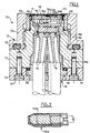
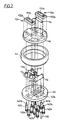
- a humidity sensor 100 comprises a thin membrane 102, produced in the present example from stainless steel, in which a plurality of through holes (not visible) are formed.
- a membrane with a thickness of the order of 0.03 mm, holes with a diameter of the order of 0.03 to 0.05 mm and a coefficient of occupation of the surface. of the membrane through the holes on the order of 20%.
- the membrane 102 can also be made of ceramic, glass or the like.
- Such a membrane is permeable to gases, while it does not pass substantially any liquid or any solid, even in powder form of small particle size.
- the membrane 102 is trapped at its edges between a flat washer 104, also made of stainless steel, and a seal 106 made of elastic material such as rubber, the assembly being fixed to a front opening of a ring of support 108.
- the membrane 102 is lined internally by a flexible membrane 110 suitable for letting through gases, and in particular water in the form of vapor, while preventing the passage of liquid water.
- a flexible membrane 110 suitable for letting through gases, and in particular water in the form of vapor, while preventing the passage of liquid water.
- an expanded polytetrafluoroethylene membrane known under the trade name "Gore-Tex” is chosen.
- a membrane is chosen whose pores have a diameter close to 0.4 ⁇ m.
- quartz sensitive elements 112a and 112b which constitute humidity sensors.
- a first quartz 114a for measuring the temperature in the environment of the said quartz 112a and 112b, as well as an electrical power resistor 116 making it possible to regulate, as will be seen below, the temperature in this environment.
- a second temperature measuring crystal 114b is located further in the sensor housing, for purposes explained below.
- the sensor also comprises a rear connector, generally indicated at 118, which allows its connection in a removable manner with its environment, as will be seen below.
- the interior space of the sensor is sealed using O-rings 120 between the various components of the sensor.
- the sensor housing which houses the above elements, is generally indicated at 130 and comprises a body 134 which can either (as illustrated) be screwed onto a casing ring 136, welded for example to the external surface of a pipe. conveying a product whose relative humidity or water activity is to be measured, or else being fixed to the end of a cane or rod (in a manner not illustrated), in order to allow its immersion in a medium whose wants to measure relative humidity or water activity.
- the housing 130 of the sensor also includes a rear plate 132.
- Bolts 137 allow the fixing of the plate 132 on the body 134.
- the connector 118 preferably made in the form of a body 118a molded in one piece, is trapped by an intermediate ring 119 between the rear retaining plate 132 and the body 134, in a cavity defined jointly by these two elements.
- the connector body 118a houses coaxial conductors 115, the ends of which are welded to male connection pins 118b fixed on a front plate 118c of the connector and able to be engaged in associated sleeves which will be described later.
- a first printed circuit 142 is received by its edges between a step of the body 134 of the sensor and an annular support element 144.
- This support element 144 also receives, on a step, a second circular printed circuit 146 located between the first circuit 142 and the membranes 102 and 110.
- the second circuit 146 carries the two humidity crystals 112a and 112b as well as the first temperature quartz 114a, which are mounted for example by soldering, while the first circuit 142, located in rear of the circuit 146 relative to the membranes 102 and 110, carries the second temperature crystal 114b and the heating resistor 116, also fixed in place by welds.
- the humidity detection crystals 112a and 112b are in the conventional form of resonant tongues or blades 1121a and 1121b, respectively, which are housed in respective housings 1122a and 1122b, preferably made of ceramic.
- the two connection terminals of each quartz tab, not visible, are provided on the underside of the respective housing, in the region of its two longitudinal ends.
- connection pins 118b of the connector 118 are connected to the connection pins 118b of the connector 118 by means of contact elements 140 each comprising at their lower part a female housing for the associated pin.
- Some contact elements 140a are electrically connected only to the lower printed circuit 142 while forming spacers between the two circuits, while other contact elements 140b have an extension 1401b which passes through the upper printed circuit and comes into contact with 'a suitable track of the latter to be welded there.
- a key 145 in association with a hole of the same diameter 142a formed in the circuit 142, ensures that the latter has the required orientation in the sensor.
- the support ring 108 mentioned above acts as a cover for the sensor. It consists of an essentially annular element internally tapped and which is capable of being screwed onto a thread 134a of the body 134 of the sensor.
- This cover 108 carries at its end the washer 104, the membrane 102 and the O-ring 106, and traps between it and the body 134 the "Gore-Tex" membrane 110 as well as an aluminum ring 111 whose role is to press the edges of said membrane 110 against the outer surface of the support 144 of the printed circuits for sealing purposes.
- FIG. 3 schematically illustrates one 1121a of the two identical tongues or quartz blades forming elements sensitive to humidity.
- the moisture-sensitive nature is obtained by coating the tongue with a material having particular properties, in particular with regard to water adsorption.
- This coating is indicated in 1123a in FIG. 3.
- these are the variations in mass of the tab and of its coating as a function of the relative humidity Hr or of the water activity aW of the medium in which the detector is located which vary the frequency of resonance of the quartz, thus detecting these variations in relative humidity or water activity.
- This principle known per se but which until now could not be used effectively to measure a continuous water activity in an industrial process, is described in the article "Piezoelectric Sorption Detector", William H. KING, Jr., journal -ANALYTICAL CHEMISTRY, vol. 36, No. 9, August 1964, p.
- materials of quite different types can satisfy the above requirements, and in particular polymers, in particular polymers with pyridine group, metals and metal oxides, semiconductors.
- a coating material chosen from the group comprising polymeric sulphonic acids, silicon oxide SiOx, a modified epoxy resin and cellulose acetate is used in the present example.
- the coating can be carried out by immersion in a solution containing the coating product dissolved in an appropriate solvent, then drying.
- the silicon oxide can be deposited by evaporation.
- any other technique can be used to carry out the coating, and in particular vacuum evaporation, sputtering, electrolytic coating, etc., the choice being made according to the nature of the material.
- the quartz tongue can be coated with the adsorbent material either on its two faces, or on one side only, or even on only part of one or both sides.
- the thickness of the coating of adsorbent material is between a fraction of a micron and a few microns, for example around 1 micron.
- tuning fork crystals are used, oscillating at frequencies of the order of 260 kHz and which have the property of reacting very quickly and very precisely to changes in temperature.
- the humidity sensor described above works as follows.
- the temperature crystals 114a, 114b have a resonant frequency which varies as a function of the temperature.
- the frequencies of the two quartzes are regularly compared and, in the event of an abnormal temperature difference, the heating resistor 116 is supplied to heat the atmosphere located in the vicinity of the second quartz 114b and thus balance the temperature within the cavity of the sensor. This minimizes the temperature gradients that may affect the accuracy of the measurements.
- the variation in frequency of the resonant blades of moisture quartz makes it easy to determine their variation in mass. Knowing the surface and the thickness of the adsorbent coating and its adsorption / desorption law as a function of the surrounding relative humidity for a given temperature, it is easy to deduce from the mass of the slide at a given time the relative humidity or water activity in its environment.
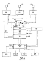
- FIG. 4 shows an installation for measuring relative humidity or water activity, and for water content, using sensors as described above and intended to be installed on an industrial site for the measurement continuous water activity of a treated product.
- This installation firstly comprises, in association with each sensor 100 as described above, an electronic interfacing module 200. There is further provided a central unit 300, a frequency meter 400 and a computer 500.
- Each module 200 is connected to the associated sensor 100 by the coaxial electric cables 115 described above, with a length of cables preferably relatively short, for example of the order of 1m.
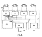
- a module 200 is shown in detail in FIG. 5.
- each module 200 is capable, under the control of the central unit 300, of applying to the optical fiber 207 at a given instant an optical signal corresponding to the electrical resonance signal of any one of the four measurement crystals; it should be noted that the use of a semiconductor selector makes it possible to send the various signals to the central unit at high rates, if necessary.
- Pierce oscillators based on NTT gateways with NAND gates are used as oscillators.
- the central unit 300 is in the present example capable of managing a set of four sensor 100 / electronic module 200 pairs.
- It includes a power supply 302 capable of delivering the stabilized DC voltages necessary to operate the various elements of the installation, and in particular the voltages of + 5V and + 12V to the modules 200 via the diagrammed lines 303.
- a power supply 302 capable of delivering the stabilized DC voltages necessary to operate the various elements of the installation, and in particular the voltages of + 5V and + 12V to the modules 200 via the diagrammed lines 303.
- optical receivers generally indicated in 304, which comprises four connectors for four optical fibers such as 207 coming from the modules 200 and which is capable of converting the optical signals received into electrical signals.
- Broadband receivers are preferably used so as to be able to receive the frequencies associated with the measurement of water activity and the frequencies associated with the measurement of temperature.
- optical fibers 207 Thanks to the use of optical fibers 207, it is possible to provide between the modules 200 and the central unit 300 an extremely long distance, of the order of one or more kilometers, which allows the installation of the installation on very large industrial sites.
- a multiplexing or selection card 306 which receives as input the four electrical signal outputs from the receiver card 304. A selection of a particular signal from these four signals is carried out by applying two two binary selection signals from of the computer 500. The output of the selector 306 is applied to the input of the frequency meter 400, as will be detailed below.
- a card 308 may possibly be provided for delivering in analog form information on water activity, water content and temperature. More specifically, it may be a digital / analog converter card which receives water activity, water content and temperature information, in digital form, from the computer 500, and which converts them in analog voltages or currents according to the current ranges of analog measuring devices.
- An extension card 310 can also be provided to deliver the same signals, but in digital form and in TTL format.
- the optional cards 308 and 310 thus allow extremely flexible connection of the assembly made up of the sensors 100, the electronic modules 200 and the central unit 300 to any kind of process management equipment or the like.
- the frequency meter 400 is preferably a digital frequency meter of conventional design and of high quality (time base thermostatically or temperature compensated).
- the computer 500 can be a commercial microcomputer, for example in PC standard. It comprises a keyboard 502, a display screen 504, for example a high-definition color screen, a printer 506 and if necessary an interface 508 for communication with a regulation or industrial process management computer of any type, indicated schematically in 600. It further comprises two interfaces 510 and 512 for the connection with the central unit and with the frequency meter, respectively.
- a main program allows the user to be presented with a menu allowing him to access five sub-programs detailed below.
- the main program also advantageously makes it possible to modify certain communication parameters, and in particular the speed of serial data transmission between the computer 500 and the industrial computer 600.
- the third block manages the serial interface 508 according to a predetermined protocol. More precisely, as soon as a message from the computer 600 appears on this interface, the subroutine of the first block is interrupted to make a connection to the third block. Depending on the type of message received, the response is either immediate or deferred until the completion of the current subroutine of the first block (especially if measurement parameters are modified).
- the third subroutine allows to select a given sensor, to choose a window, to apply it to the last X measurements stored to extract the measurements entering this window, in particular for viewing and / or creation of a specific file on floppy disk or hard disk.
- the fourth subroutine accessible from the main program is intended to allow the recalibration of a sensor.
- a standard solution of an unsaturated salt is then used, the law of evolution of the relative humidity as a function of the temperature is perfectly known.
- the sensor is placed so as to be in contact with this solution, and the subroutine is then placed in a waiting phase for pressure stabilization. Once this stabilization is reached, the recalibration is carried out by comparing the values supplied by the sensor with the expected, known values.
- the fifth subroutine is a user help program, which can be called at any time.
- the present invention advantageously applies to the measurement of relative humidity, water activity and water content of any kind of solid product, for example in granular or pulverulent form.
- the measurement can also be carried out in conjunction with dryers or mixers for any products.
Landscapes
- Physics & Mathematics (AREA)
- Acoustics & Sound (AREA)
- Health & Medical Sciences (AREA)
- Life Sciences & Earth Sciences (AREA)
- Chemical & Material Sciences (AREA)
- Analytical Chemistry (AREA)
- Biochemistry (AREA)
- General Health & Medical Sciences (AREA)
- General Physics & Mathematics (AREA)
- Immunology (AREA)
- Pathology (AREA)
- Investigating Or Analyzing Materials By The Use Of Electric Means (AREA)
- Investigating Or Analyzing Materials By The Use Of Fluid Adsorption Or Reactions (AREA)
- Testing Or Calibration Of Command Recording Devices (AREA)
Applications Claiming Priority (2)
| Application Number | Priority Date | Filing Date | Title |
|---|---|---|---|
| FR9000128 | 1990-01-08 | ||
| FR9000128A FR2656925B1 (fr) | 1990-01-08 | 1990-01-08 | Capteur d'humidite et installation de mesure comportant une pluralite de tels capteurs. |
Publications (1)
| Publication Number | Publication Date |
|---|---|
| EP0441665A1 true EP0441665A1 (de) | 1991-08-14 |
Family
ID=9392571
Family Applications (1)
| Application Number | Title | Priority Date | Filing Date |
|---|---|---|---|
| EP91400026A Ceased EP0441665A1 (de) | 1990-01-08 | 1991-01-08 | Feuchtigkeitsprobe und Messvorrichtung mit einer Vielheit von solchen Proben |
Country Status (4)
| Country | Link |
|---|---|
| US (1) | US5189902A (de) |
| EP (1) | EP0441665A1 (de) |
| CA (1) | CA2033688A1 (de) |
| FR (1) | FR2656925B1 (de) |
Cited By (1)
| Publication number | Priority date | Publication date | Assignee | Title |
|---|---|---|---|---|
| WO2013139912A1 (fr) * | 2012-03-22 | 2013-09-26 | Adria Developpement | Procédé et dispositif de traitement d'un produit composé partiellement d'eau |
Families Citing this family (38)
| Publication number | Priority date | Publication date | Assignee | Title |
|---|---|---|---|---|
| DE4219287A1 (de) * | 1992-06-12 | 1993-12-16 | Merck Patent Gmbh | Anorganische Füllstoffe und organische Matrixmaterialien mit Brechungsindex-Anpassung |
| US5339675A (en) * | 1992-10-08 | 1994-08-23 | Millipore Corporation | Apparatus for monitoring impurities in a gas stream |
| USRE35544E (en) * | 1992-10-08 | 1997-07-01 | Millipore Corporation | Apparatus for monitoring moisture in a gas stream |
| US5677476A (en) * | 1996-02-06 | 1997-10-14 | Endress + Hauser Conducta Gesellschaft Fuer Mess- Und Regeltechnik Mbh & Co. | Sensor and transmitter with multiple outputs |
| US5852229A (en) * | 1996-05-29 | 1998-12-22 | Kimberly-Clark Worldwide, Inc. | Piezoelectric resonator chemical sensing device |
| US6020047A (en) * | 1996-09-04 | 2000-02-01 | Kimberly-Clark Worldwide, Inc. | Polymer films having a printed self-assembling monolayer |
| US6048623A (en) * | 1996-12-18 | 2000-04-11 | Kimberly-Clark Worldwide, Inc. | Method of contact printing on gold coated films |
| US5922550A (en) * | 1996-12-18 | 1999-07-13 | Kimberly-Clark Worldwide, Inc. | Biosensing devices which produce diffraction images |
| US6111512A (en) * | 1997-03-13 | 2000-08-29 | Nippon Telegraph And Telephone Corporation | Fire detection method and fire detection apparatus |
| US6180288B1 (en) | 1997-03-21 | 2001-01-30 | Kimberly-Clark Worldwide, Inc. | Gel sensors and method of use thereof |
| US6060256A (en) * | 1997-12-16 | 2000-05-09 | Kimberly-Clark Worldwide, Inc. | Optical diffraction biosensor |
| US6221579B1 (en) | 1998-12-11 | 2001-04-24 | Kimberly-Clark Worldwide, Inc. | Patterned binding of functionalized microspheres for optical diffraction-based biosensors |
| US6579673B2 (en) | 1998-12-17 | 2003-06-17 | Kimberly-Clark Worldwide, Inc. | Patterned deposition of antibody binding protein for optical diffraction-based biosensors |
| JP2003513238A (ja) * | 1999-10-27 | 2003-04-08 | モイア,ピーター,ドナルド | 材料安定性試験キット |
| US7167615B1 (en) | 1999-11-05 | 2007-01-23 | Board Of Regents, The University Of Texas System | Resonant waveguide-grating filters and sensors and methods for making and using same |
| US6399295B1 (en) | 1999-12-17 | 2002-06-04 | Kimberly-Clark Worldwide, Inc. | Use of wicking agent to eliminate wash steps for optical diffraction-based biosensors |
| DE10104942A1 (de) * | 2000-02-11 | 2001-08-16 | E & E Elektronik Gmbh | Sensoranordnung |
| US7098041B2 (en) | 2001-12-11 | 2006-08-29 | Kimberly-Clark Worldwide, Inc. | Methods to view and analyze the results from diffraction-based diagnostics |
| US7102752B2 (en) | 2001-12-11 | 2006-09-05 | Kimberly-Clark Worldwide, Inc. | Systems to view and analyze the results from diffraction-based diagnostics |
| US7485453B2 (en) * | 2002-05-03 | 2009-02-03 | Kimberly-Clark Worldwide, Inc. | Diffraction-based diagnostic devices |
| US7214530B2 (en) * | 2002-05-03 | 2007-05-08 | Kimberly-Clark Worldwide, Inc. | Biomolecule diagnostic devices and method for producing biomolecule diagnostic devices |
| US7223368B2 (en) * | 2002-05-03 | 2007-05-29 | Kimberly-Clark Worldwide, Inc. | Diffraction-based diagnostic devices |
| US7118855B2 (en) * | 2002-05-03 | 2006-10-10 | Kimberly-Clark Worldwide, Inc. | Diffraction-based diagnostic devices |
| US7223534B2 (en) * | 2002-05-03 | 2007-05-29 | Kimberly-Clark Worldwide, Inc. | Diffraction-based diagnostic devices |
| US7771922B2 (en) * | 2002-05-03 | 2010-08-10 | Kimberly-Clark Worldwide, Inc. | Biomolecule diagnostic device |
| US7091049B2 (en) * | 2002-06-26 | 2006-08-15 | Kimberly-Clark Worldwide, Inc. | Enhanced diffraction-based biosensor devices |
| US7169550B2 (en) * | 2002-09-26 | 2007-01-30 | Kimberly-Clark Worldwide, Inc. | Diffraction-based diagnostic devices |
| DE10337306A1 (de) * | 2003-08-14 | 2005-03-10 | Il Metronic Sensortechnik Gmbh | Verfahren und Anordnung zur Messung der Wasseraktivität |
| AU2003248295A1 (en) * | 2003-09-24 | 2005-04-14 | The Commonwealth Of Australia, C/O Minister For Defence | Apparatus for Measuring Water Concentration in Multi-Component Solutions |
| US7059170B2 (en) * | 2004-02-27 | 2006-06-13 | Nielsen-Kellerman, Inc. | Method and apparatus for measuring relative humidity of a mixture |
| US20070017276A1 (en) * | 2005-07-20 | 2007-01-25 | Trutna William R Jr | Resonant structure humidity sensor |
| US7658096B2 (en) * | 2008-02-27 | 2010-02-09 | Setra Systems, Inc. | Humidity sensing apparatus |
| US8249811B2 (en) | 2008-07-09 | 2012-08-21 | Honeywell International Inc. | Multi-sensor detectors |
| US8015872B2 (en) * | 2008-09-09 | 2011-09-13 | Honeywell International Inc. | Surface acoustic wave based humidity sensor apparatus with integrated signal conditioning |
| WO2014091372A1 (en) * | 2012-12-11 | 2014-06-19 | Koninklijke Philips N.V. | A method and apparatus for determining water content of food |
| US9388998B2 (en) * | 2013-03-15 | 2016-07-12 | Honeywell International Inc. | Battery holder for an electronic device |
| JP6317643B2 (ja) | 2014-07-31 | 2018-04-25 | 日本特殊陶業株式会社 | ガス検出装置 |
| DE102022129141A1 (de) | 2021-11-05 | 2023-05-11 | HELLA GmbH & Co. KGaA | Verfahren zur Bestimmung des Zustandes eines piezoelektrischen Elementes und Sensorvorrichtung mit einem piezoelektrischen Element |
Citations (2)
| Publication number | Priority date | Publication date | Assignee | Title |
|---|---|---|---|---|
| US3534585A (en) * | 1967-12-07 | 1970-10-20 | Webb James E | Microbalance including crystal oscillators for measuring contaminates in a gas system |
| EP0072744A2 (de) * | 1981-08-17 | 1983-02-23 | Allied Corporation | Chemischer Fühler |
Family Cites Families (4)
| Publication number | Priority date | Publication date | Assignee | Title |
|---|---|---|---|---|
| SU932390A1 (ru) * | 1980-05-30 | 1982-05-30 | Рязанский Радиотехнический Институт | Влагочувствительный элемент |
| JPS5886447A (ja) * | 1981-11-18 | 1983-05-24 | Tokyo Kosumosu Denki Kk | 湿度センサ |
| CH662421A5 (de) * | 1983-07-13 | 1987-09-30 | Suisse Horlogerie Rech Lab | Piezoelektrischer kontaminationsdetektor. |
| GB2178539B (en) * | 1985-06-26 | 1989-02-08 | Eps Group Limited | Improvements in or relating to a humidity sensor |
-
1990
- 1990-01-08 FR FR9000128A patent/FR2656925B1/fr not_active Expired - Fee Related
-
1991
- 1991-01-07 CA CA002033688A patent/CA2033688A1/fr not_active Abandoned
- 1991-01-08 US US07/638,838 patent/US5189902A/en not_active Expired - Fee Related
- 1991-01-08 EP EP91400026A patent/EP0441665A1/de not_active Ceased
Patent Citations (2)
| Publication number | Priority date | Publication date | Assignee | Title |
|---|---|---|---|---|
| US3534585A (en) * | 1967-12-07 | 1970-10-20 | Webb James E | Microbalance including crystal oscillators for measuring contaminates in a gas system |
| EP0072744A2 (de) * | 1981-08-17 | 1983-02-23 | Allied Corporation | Chemischer Fühler |
Non-Patent Citations (2)
| Title |
|---|
| ADVANCES IN INSTRUMENTATION, vol. 41, partie 1, 1986, pages 301-301, Research Triangle Park, NC, US; W.P. CAREY et al.: "The IBM-XT and sensor arrays for environmental monitoring" * |
| SENSORS AND ACTUATORS, vol. 11, no. 4, mai/juin 1987, pages 319-328, Lausanne, CH; J.-P. RANDIN et al.: "Relative humidity measurements using a coated piezoelectric quartz crystal sensor" * |
Cited By (2)
| Publication number | Priority date | Publication date | Assignee | Title |
|---|---|---|---|---|
| WO2013139912A1 (fr) * | 2012-03-22 | 2013-09-26 | Adria Developpement | Procédé et dispositif de traitement d'un produit composé partiellement d'eau |
| FR2988269A1 (fr) * | 2012-03-22 | 2013-09-27 | Adria Dev | Procede et dispositif de traitement d'un produit compose partiellement d'eau |
Also Published As
| Publication number | Publication date |
|---|---|
| CA2033688A1 (fr) | 1991-07-09 |
| FR2656925B1 (fr) | 1992-05-15 |
| FR2656925A1 (fr) | 1991-07-12 |
| US5189902A (en) | 1993-03-02 |
Similar Documents
| Publication | Publication Date | Title |
|---|---|---|
| FR2656925A1 (fr) | Capteur d'humidite et installation de mesure comportant une pluralite de tels capteurs. | |
| EP0426550B1 (de) | Vorrichtung zur Bestimmung des Ausdehnungskoeffizienten durch Wasserabsorption von Elementen einer Verbundstruktur | |
| FR2760092A1 (fr) | Dispositif formant detecteur d'humidite du type a resistance electrique | |
| EP2135050B1 (de) | Radiometrisches thermometer | |
| FR2847981A1 (fr) | Thermometre electronique medical, procede d'assemblage et structure | |
| EP0467759A1 (de) | Vorrichtung zum Feststellen der Viskositätsänderung eines flüssigen Elektrolyts mittels Depolarisierungswirkung | |
| WO2010082006A1 (fr) | Micro-capteur réalisé en technologies microsystèmes pour la mesure et/ou la détection de l'encrassement | |
| CH675634A5 (de) | ||
| FR2764385A1 (fr) | Microsysteme d'analyse de liquides a cuvette integree | |
| EP0114013B1 (de) | Temperaturregelungssystem für eine thermisch erregte Einrichtung | |
| EP1565717A2 (de) | Optische vorrichtung zum feststellen der anwesenheit von gasblasen in einer flüssigkeit | |
| WO2017006036A1 (fr) | Système d'analyse d'un échantillon liquide | |
| EP3973259B1 (de) | Infrarotlicht-ausstrahlende und -kontrollierende vorrichtung und gassensor mit einer solchen vorrichtung | |
| EP1084404A1 (de) | Vorrichtung zum messen der elektrophysiologischen aktivität einer zellanordnung | |
| CA2457616A1 (fr) | Dispositif de mesure d'au moins un parametre physique dans une cavite de l'organisme d'un etre vivant | |
| CA2629058A1 (fr) | Dispositif d'analyse de la composition du contenu d'un recipient comprenant des moyens pour l'obtention d'au moins une donnee physique additionnelle relative au recipient | |
| EP0668999A1 (de) | Vorrichtung zum messen der qualität von fleisch. | |
| CA2976024A1 (fr) | Dispositif de captage d'au moins une espece chimique comprenant un capteur chimique et procede de fabrication d'un tel capteur chimique | |
| EP0279132B1 (de) | Vorrichtung zur Feststellung der Lage einer Vielzahl von Magnetköpfen | |
| CH574105A5 (en) | Measurement of density and water content esp. for snow - by measuring permittivity using two different frequencies | |
| EP0094266A2 (de) | Verfahren zur Herstellung eines Temperatur- oder Feuchtigkeitsfühlers aus dünnen Schichten und Fühler | |
| FR2925668A1 (fr) | Procede de correction de gain d'un organe capacitif et dispositif de mise en oeuvre | |
| EP3317017A1 (de) | Vorrichtung zur analyse einer flüssigkeitsprobe mit einer verriegelungs- und entnahmevorrichtung | |
| EP3631430A1 (de) | Elektrochemische messkassette | |
| FR2718528A1 (fr) | Appareil pour l'analyse en ligne de produits fluides polyphasés. |
Legal Events
| Date | Code | Title | Description |
|---|---|---|---|
| PUAI | Public reference made under article 153(3) epc to a published international application that has entered the european phase |
Free format text: ORIGINAL CODE: 0009012 |
|
| AK | Designated contracting states |
Kind code of ref document: A1 Designated state(s): BE CH DE ES FR GB IT LI NL |
|
| 17P | Request for examination filed |
Effective date: 19920210 |
|
| 111L | Licence recorded |
Free format text: 0100 LE BOZEC AERONAUTIQUE |
|
| 17Q | First examination report despatched |
Effective date: 19931125 |
|
| GRAG | Despatch of communication of intention to grant |
Free format text: ORIGINAL CODE: EPIDOS AGRA |
|
| STAA | Information on the status of an ep patent application or granted ep patent |
Free format text: STATUS: THE APPLICATION HAS BEEN REFUSED |
|
| REG | Reference to a national code |
Ref country code: CH Ref legal event code: PLI Owner name: EG ET G TRANSFER- LE BOZEC AERONAUTIQUE |
|
| 18R | Application refused |
Effective date: 19960929 |