EP0441919B1 - Element de meuble pour la mise en place dans un coin rectangulaire d'une piece - Google Patents
Element de meuble pour la mise en place dans un coin rectangulaire d'une piece Download PDFInfo
- Publication number
- EP0441919B1 EP0441919B1 EP90911989A EP90911989A EP0441919B1 EP 0441919 B1 EP0441919 B1 EP 0441919B1 EP 90911989 A EP90911989 A EP 90911989A EP 90911989 A EP90911989 A EP 90911989A EP 0441919 B1 EP0441919 B1 EP 0441919B1
- Authority
- EP
- European Patent Office
- Prior art keywords
- frame
- unit
- guide
- built
- furniture
- Prior art date
- Legal status (The legal status is an assumption and is not a legal conclusion. Google has not performed a legal analysis and makes no representation as to the accuracy of the status listed.)
- Expired - Lifetime
Links
- 238000009434 installation Methods 0.000 title claims abstract description 49
- 238000003860 storage Methods 0.000 claims abstract description 26
- 229910000831 Steel Inorganic materials 0.000 description 3
- 238000006073 displacement reaction Methods 0.000 description 3
- 239000010959 steel Substances 0.000 description 3
- 238000004519 manufacturing process Methods 0.000 description 2
- 208000031872 Body Remains Diseases 0.000 description 1
- 238000005452 bending Methods 0.000 description 1
- 230000000903 blocking effect Effects 0.000 description 1
- 238000004140 cleaning Methods 0.000 description 1
- 238000010276 construction Methods 0.000 description 1
- 230000007423 decrease Effects 0.000 description 1
- 239000010438 granite Substances 0.000 description 1
- 239000011265 semifinished product Substances 0.000 description 1
- 239000000725 suspension Substances 0.000 description 1
- 238000003466 welding Methods 0.000 description 1
Images


Classifications
-
- A—HUMAN NECESSITIES
- A47—FURNITURE; DOMESTIC ARTICLES OR APPLIANCES; COFFEE MILLS; SPICE MILLS; SUCTION CLEANERS IN GENERAL
- A47B—TABLES; DESKS; OFFICE FURNITURE; CABINETS; DRAWERS; GENERAL DETAILS OF FURNITURE
- A47B57/00—Cabinets, racks or shelf units, characterised by features for adjusting shelves or partitions
- A47B57/06—Cabinets, racks or shelf units, characterised by features for adjusting shelves or partitions with means for adjusting the height of the shelves
- A47B57/16—Cabinets, racks or shelf units, characterised by features for adjusting shelves or partitions with means for adjusting the height of the shelves consisting of hooks coacting with openings
-
- A—HUMAN NECESSITIES
- A47—FURNITURE; DOMESTIC ARTICLES OR APPLIANCES; COFFEE MILLS; SPICE MILLS; SUCTION CLEANERS IN GENERAL
- A47B—TABLES; DESKS; OFFICE FURNITURE; CABINETS; DRAWERS; GENERAL DETAILS OF FURNITURE
- A47B81/00—Cabinets or racks specially adapted for other particular purposes, e.g. for storing guns or skis
- A47B81/002—Corner cabinets; Cabinets designed for being placed in a corner or a niche
Definitions
- the invention relates to a furniture unit according to the preamble of independent claim 1.
- the walls that enclose an angle of 90 °, for example, should also be covered with furniture.
- the corner room often remains unused because the furniture pieces attached to the two walls would at least partially inaccessible furniture filling this corner room.
- a furniture unit which avoids this inaccessibility and is intended for installation in a rectangular corner of a room has been described in CH-A-593 657.
- This known furniture unit has two horizontally displaceable built-in elements, the outer built-in element being pullable out of the base body and pivotable about a vertical one from the corner of the room.
- the two sliding installation elements are connected to one another by levers so that when the outer installation element is pivoted about the vertical axis, the installation element located in the corner is displaced horizontally within the base body and in the direction of the same to the place that was originally occupied by the swiveled-out installation element is.
- the built-in elements used in the known version each contain a body that can be cut. The interior of the body must be used to store those in the furniture unit Objects equipped with storage elements, for example in the form of shelves or wire mesh baskets.
- the body can be formed, for example, from a wooden box open on the front or from a welded steel frame.
- the known design of a furniture element for installation in the corner of a room has disadvantages, in particular due to the size and the spatial expansion of the body. These disadvantages mainly concern the installation of the device, but also its flexibility with regard to its use in furniture of different dimensions and designs.
- the body is designed as a spatially relatively bulky part which is to be inserted into the pre-assembled furniture unit, fastened there and connected to the lever system.
- the guides can be tilted. This can make the horizontally displaceable built-in elements difficult to move and thus impair the function of the furniture unit.
- the known furniture unit is hardly suitable for such applications as are e.g. resulting from sales through do-it-yourself retailers.
- the invention is therefore based on the object of creating a furniture unit for installation in a corner of a room, the manufacture and assembly being considerably simplified and accelerated and the risk of canting of the horizontally displaceable installation elements being eliminated as far as possible. In doing so, if possible even simpler parts than those used in the known solution are used.
- Another object of the invention is to design the fittings used for the sliding device in such a way that their use is possible in a large number of differently designed pieces of furniture.
- the device should be adaptable to different dimensions and designs of built-in wardrobes depending on the country-specific standard, or together with different cover plates, e.g. Granite slabs can be used. This is achieved in particular by the special design of the guide frame in the first embodiment of the invention.
- the installation elements are essentially designed such that the storage elements are suspended on one side in a flat frame after all other components have been installed.
- This displaceable flat frame hereinafter referred to as the running frame, is mounted horizontally displaceably on an equally flat guide frame.
- the body is no longer designed as a part with a spatial extension.
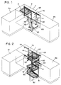
- a base body 1 for example a wooden body, is installed in a corner of a room.
- a number of storage elements are located within the base body 14 having built-in elements 3, 4, wherein for reasons of clarity only the inner built-in element 3 is provided with a single storage element 14.
- the remaining storage elements 14 which can be used on the inner installation element 3 and on the outer installation element 4 are not shown.
- Any other furniture elements 2a, 2b are connected to the base body 1. Due to the vicinity of the transversely connecting element 2a, the inner built-in element 3 would not be accessible from the outside in a conventional furniture unit.
- a lever mechanism has been proposed in CH-A-593 657, with which an inevitable displacement of the inner installation element 3 is possible if the outer installation element 4, after it has been pulled out of the base body 1, then about a vertical axis is pivoted.
- This known lever device is also used in the present invention.
- Fig. 1 the angled lever 50 can be seen, which is attached so that it forms a kinematic chain when interacting with the connecting lever 60, via which a displacement of the inner mounting element 3 is achieved to the externally accessible space when the outer Installation element 4 is pivoted about the vertical axis 100.
- the invention provides that the running frame 80 of the outer installation element 4, which has just been executed, is attached to a pivotable guide unit 90 so as to be longitudinally displaceable.
- the pivotable guide unit 90 receiving the moving frame 80 of the outer installation element 4 is attached to the side facing away from the inner installation element 3, and is in turn by means of the vertical one Hinge joints 101 forming the pivot axis 100 are connected to the base body 1.
- a flat guide frame 70 is arranged vertically in the rear part of the furniture unit.
- This guide frame 70 has running rails which have the task of guiding the running frame 120 of the inner installation element 3 so that it can be moved horizontally. The movements are coupled via the two levers 50, 60.
- FIG. 2 shows the furniture unit according to the invention in such a state that it assumes when the outer installation element 4 is pulled out of the base body 1 and pivoted about the vertical axis 100.
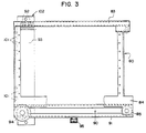
- Fig. 3 is a side view of the running frame of the outer installation element 4 in the closed state of the furniture unit, i.e. the running frame 80 is in the pivoted-in and pushed-in state.
- the figure shows another possible embodiment of the design of the pivotable guide unit 90 and the guides for the sliding movement of the running frame 80 relative to the guide unit.
- the upper rail 83 of the running frame 80 is guided only by means of the pivotable guide unit 90 Guide rollers 92.
- the vertical part 93 of the pivotable guide unit 90 is attached to the fixed support unit 102.
- a running roller 85 is provided, which runs on the rail part 91 of the pivotable guide unit 90 rolls.
- the pivotable guide unit 90 is provided with a further roller 94, on which the lower rail 84 of the frame 80 rolls when it is pulled out of the base body.
- the rail part 91 of the pivotable guide unit 90 is provided on the lower edge with a slider 95, which serves to drive the pivoting movement of the angled lever 50 in a manner known per se. It is clear from the illustration in FIG. 3 that the roller 85 present at the corner of the running frame 80 is moved in the direction of the running roller 94 connected to the guide element 90 when the running frame 80 is pulled out, the mentioned running roller 94 initially opposite the base body remains stationary.
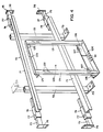
- Fig. 4 is a perspective view of the main components of the inner mounting member.
- the running frame 120 is essentially formed by the vertical struts 121 and the horizontal struts 123, 124.
- the vertical struts 121 are each provided on their front side at the same height with a number of hooks 122, which are preferably arranged at a constant distance from one another.
- the storage elements (not shown) are attached after assembly is complete.
- the storage elements are designed, for example, in the form of baskets, bowl-shaped bodies or plate-shaped bodies made of flat steel wire elements. These are attached on one side to the respective running arms of the inner or outer installation element in such a way that they form a right angle with respect to the flat frame.
- the right-angled protrusion of the storage elements from the running frame is ensured in that the lower region of the storage elements is supported with respect to the frame.
- the storage elements have a certain height, ie a sufficient distance between the parts interacting with the hooks 122 and their lower part.
- FIG. 6 Another embodiment of the attachment of the storage elements 14 relative to the respective moving frame is shown in FIG. 6.
- the respective moving frame is provided with holes into which the respective fastening elements of the storage element 14 are hung.
- the principle of this hanging is known as such and can be seen from the illustration in FIG. 6.
- the embodiment of the attachment of the storage elements 14 shown in FIG. 6 can also be used in the case of the embodiment of the running frame shown in FIG. 4.
- the running frame 80 of the outer installation element shown in FIG. 3 the latter is provided with bores in order, for example, to accommodate storage elements according to the embodiment shown in FIG. 6.
- the embodiment of the attachment of the storage elements relative to the running frame based on the use of hook-shaped fastening elements according to FIG. 6 can also be used in this exemplary embodiment.
- the one-sided suspension of the storage elements 14 on the respective running frame is a basic requirement for the inventive design of the respective running frame as a flat component.
- excellent handling and flexibility of the storage elements is ensured as a result of the possible types of fastening of the storage elements.
- the storage elements can be easily replaced or, in order to be able to carry out cleaning work, for example, simply removed. This provides easy access to the installation elements.
- the horizontal struts 123, 124 of the running frame 120 which can be seen in FIG. 4 are equipped on the rear side with a number of guide rollers 125, 126, 127, which have the task of guiding the running frame 120 in a longitudinally displaceable manner relative to the fixed guide frame 70.
- the fixed guide frame 70 comprises two struts 71 which run at a corresponding distance from one another in the horizontal direction and which serve as rails for rollers present on the running frame 120. At the rear, these rails 71 are connected to one another by means of two vertically extending connecting struts 72. On the underside, these connecting struts 72 are equipped with support feet 73 which can be fastened to the floor. For fixing these support feet 73 on the floor are preferably provided with through holes.
- the rails 71 are each provided with support arms 75 at their ends.
- the support arms 75 end with flange plates 76, which in turn are preferably provided with through holes for wall mounting.
- the support arms 75 are each guided in a sleeve 74, so that the former can be displaced in the direction of the rails 71.
- the sleeves 74 are each equipped with a threaded hole in which a clamping screw 77 is provided.
- the inner cross-section of the sleeves 74 has a preferably rectangular cross-sectional shape corresponding to the outer cross-section of the support arms 75, and the sleeves 74 are each attached at the end of the rail 71 to the rear side thereof, preferably by welding.
- the cross section of the sleeves 74 preferably corresponds to that of the connecting struts 72, or at least their inner cross section also corresponds to the outer cross section of the support arms 75.
- the fixed guide frame 70 could, for example, be fastened to the floor, to a side wall (right or left) and to the cover plate which closes the furniture unit upwards.
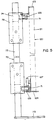
- FIG. 5 a side view of the components shown in the previous FIG. 4 is given, which, however, are in the functional, assembled state in FIG. 5.
- the running frame 120 of the inner installation element is formed by the struts 121, 123 and 124, the horizontal struts 123, 124 carrying the corresponding running rollers 125, 126, 127.
- the pairs of rollers 125, 126 are horizontal Direction oriented, ie they rotate around vertical axes. In connection with their arrangement in the respective rail 71, it is clear that these pairs of rollers 125, 126 rotating about vertical axes take over the guidance of the running frame 120 in the horizontal direction. It goes without saying that the diameter of the rollers 125, 126 has to be slightly smaller than the inner width of the profiles 71. In this way it is ensured that the horizontal guidance of the running frame 120 takes place with as little play as possible and, on the other hand, on the rail / roller -Pairing no sliding friction arises.
- the vertical guidance of the running frame 120 with respect to the fixed guide frame 70 takes place by means of the pair of rollers 127.
- the roller 127 shown in FIG. 5 is arranged in the vertical direction, i.e. it rotates about a horizontal axis connected to the lower horizontal strut 124. This roller 127 rolls on the upper surface of the lower rail 71.
- the assembly of the running frame 120 on the guide frame 70 preferably has to be carried out before the latter is installed in the base body in such a way that the running frame 120 is pushed onto the rails 71 from one end thereof.
- assembly of the running frame 120 is in principle also possible in such a way that the rollers of one side of the running frame 120, for example the left side, are pushed onto the corresponding, for example also left end of the rails 71, and then the Unilaterally mounted moving frame to the other, so the right end of the guide frame 70 moved and there the roles of the others Side of the running frame are pushed onto the rails 71 of the guide frame 70 from its corresponding side.
- FIG. 6 shows a further embodiment with regard to the design of the inner built-in element from largely flat components.
- the guidance of the running frame of the inner built-in element by means of a fixed guide frame arranged vertically in the rear area of the furniture element in the embodiment to be described now the guide frame is arranged horizontally in the upper area of the furniture element.
- the guide frame 7 consists of a pair of rails 7b which are connected to one another by means of connecting struts 7a.
- the running frame 12 is designed as a two-part unit, consisting of a carriage 12a and a support frame 13, to which the storage elements 14 can be attached.
- the carriage 12a which can be moved in the rails 7 via rollers 15 consists of a frame formed from a pair of longitudinal struts 16 and transverse struts 17 and a diagonal strut 17a, from which vertical struts 18 extend downward at the rear edge.
- the lower end of the vertical struts 18 is connected by means of support struts 19 to the front region of the frame, ie to the front region of the cross struts 17, for the purpose of absorbing bending moments acting on the vertical struts 18.
- the vertical struts 18 of the carriage 12a are preferably formed from L-profiles and welded to the frame formed from the longitudinal and transverse struts 16, 17.
- the vertical struts 18 are each in the upper region with a bore running in the longitudinal direction of the rail 7b 20 provided.
- Support bolts 21 are each firmly connected to the upper end of the support frame 13 of the inner installation element, for example welded. The distance between the two vertical struts 18 is dimensioned such that the support frame 13 finds space just between the L-profiles. After the mounting frame has been installed, the support bolts 21 come into engagement with the bores 20 present in the vertical struts 18.
- the support frame 13 To mount the support frame 13, it is pressed together in the open upper area to such an extent that the outer ends of the support bolts 21 can be inserted into the bores 20 from the inside.
- the pressure on the support frame 13 decreases, it springs back and now hangs on the support bolt 21 which is supported in the bores 20 and its position is simultaneously fixed by the L-profiles of the vertical struts 18.
- the rear cheeks 18a of the L-profiles prevent the hanging support frame from pivoting backwards.
- FIG. 7 shows a plan view of a furniture unit according to the second embodiment of the invention, the cover plate of the furniture being removed.
- the state is shown in solid lines, in which the inner installation element 3 is in place and the outer installation element 4 is pulled out of the base body.
- the angled lever 50 can be pivoted about a pivot point 51 fixed on the base of the base body and on the side which is connected to the rail part 91 pivotable guide unit 90 is connected, formed as a guide 52. A with the rail part 91 connected slider 95 slides in this guide 52.
- the angled lever 50 is connected to a connecting lever 60, which in turn is articulated on the running frame of the inner installation element.
- a furniture unit for installation in a corner of a room can be designed with simpler means and fewer parts than before.
- the individual parts provided according to the invention are suitable for a large number of designs and dimensions of the piece of furniture, the assembly of the installation elements, which consist essentially of flat parts, is considerably simplified and the operational safety, i.e. Security against jamming and blocking of the moving elements, significantly increased.
Landscapes
- Assembled Shelves (AREA)
- Legs For Furniture In General (AREA)
- Cabinets, Racks, Or The Like Of Rigid Construction (AREA)
- Combinations Of Kitchen Furniture (AREA)
- Drawers Of Furniture (AREA)
Claims (6)
- Elément de meuble destiné à être mis en place dans un coin d'une pièce, deux éléments encastrés (3,4) disposés côte à côte, déplaçables horizontalement étant installés dans un corps de base (1), lesdits éléments encastrés étant reliés par des leviers (50,60), de telle manière que, en faisant pivoter de presque 90° autour d'un axe vertical (100) l'élément encastré (4) coulissant vers la face frontale du corps de base, sur un dispositif de guidage (90) pivotant, disposé de manière déplaçable à l'extérieur, l'élément encastré intérieur est déplacé vers la place libre ou depuis la place libre, caractérisé en ce que les éléments encastrés sont constitués d'une pluralité d'éléments de corbeilles (14) horizontaux espacés, disposés chaque fois à travers un cadre mobile (80,120;12) plat disposé verticalement, lesdits éléments de corbeille étant suspendus d'un côté sur ledit cadre mobile, et en ce que le cadre mobile (120) de l'élément encastré intérieur (3) est fixé de manière mobile à un cadre de guidage (70) plat fixe.
- Elément de meuble selon la revendication 1, caractérisé en ce que le cadre de guidage (70) est disposé verticalement sur la partie arrière du corps de base.
- Elément de meuble selon la revendication 2, caractérisé en ce que le cadre de guidage (70) fixe comprend un rail de guidage supérieur et un rail de guidage inférieur (71) pour recevoir le cadre mobile (120) et en ce que le cadre mobile (120) comprend plusieurs roulettes de conduite et de guidage (125,126, 127) coopérant avec les rails de guidage (71) du cadre de guidage (70).
- Elément de meuble selon l'une des revendications 2 ou 3, caractérisé en ce que le cadre de guidage fixe (70)
peut être fixé par des pieds supports (73) disposés sur son côté inférieur au sol de la pièce ou du corps de base, et
peut être fixé par des bras supports (75) disposés sur les bordures de cadre droite et/ou gauche à une ou à deux parois latérales opposées, et/ou
peut être fixé par des bras support disposés sur les bordures de cadre supérieures à une plaque de couverture. - Elément de meuble selon la revendication 4, caractérisé en ce que la distance entre les bras support et les bordures de cadre est chaque fois ajustable.
- Elément de meuble selon la revendication 1, caractérisé en ce que le cadre de guidage (7) est disposé horizontalement dans le corps de base, dans la moitié supérieure de l'élément encastré, et en ce que le cadre mobile (12) de l'élément encastré intérieur est relié de manière mobile au cadre de guidage (7) au moyen d'un chariot (12a) mobile sur le cadre de guidage (7), le cadre mobile (12) comportant en outre un cadre porteur (13) ouvert sur le dessus avec des chevilles porteuses (21) distantes sur la partie supérieure et sur les deux côtés du cadre, pour coopérer avec des trous (20) disposés sur des montants (18) verticaux du chariot (12a), et en ce que le cadre porteur (13) peut être monté sur le chariot (12a) par une pression élastique sur les deux côtés de la partie supérieure, et en ce que les montants verticaux (18) du chariot (12a), munis de trous (20) pour recevoir les chevilles porteuses (21), sont prolongés vers le bas afin de supporter le couple de renversement produit par les corbeilles (14).
Applications Claiming Priority (2)
| Application Number | Priority Date | Filing Date | Title |
|---|---|---|---|
| DE8910549U | 1989-09-04 | ||
| DE8910549U DE8910549U1 (de) | 1989-09-04 | 1989-09-04 | Möbeleinheit zum Aufstellen in einer rechtwinkligen Ecke eines Raumes |
Publications (2)
| Publication Number | Publication Date |
|---|---|
| EP0441919A1 EP0441919A1 (fr) | 1991-08-21 |
| EP0441919B1 true EP0441919B1 (fr) | 1993-03-31 |
Family
ID=6842538
Family Applications (1)
| Application Number | Title | Priority Date | Filing Date |
|---|---|---|---|
| EP90911989A Expired - Lifetime EP0441919B1 (fr) | 1989-09-04 | 1990-08-17 | Element de meuble pour la mise en place dans un coin rectangulaire d'une piece |
Country Status (7)
| Country | Link |
|---|---|
| EP (1) | EP0441919B1 (fr) |
| AT (1) | ATE87443T1 (fr) |
| CA (1) | CA2040433A1 (fr) |
| DE (2) | DE8910549U1 (fr) |
| DK (1) | DK0441919T3 (fr) |
| ES (1) | ES2040128T3 (fr) |
| WO (1) | WO1991003189A1 (fr) |
Cited By (1)
| Publication number | Priority date | Publication date | Assignee | Title |
|---|---|---|---|---|
| US11253063B2 (en) | 2020-07-08 | 2022-02-22 | Hardware Resources, Inc. | Blind corner pullout and method of use |
Families Citing this family (14)
| Publication number | Priority date | Publication date | Assignee | Title |
|---|---|---|---|---|
| DE4323407C2 (de) * | 1993-07-13 | 1996-12-12 | Michael Deller | Schrank, insbesondere zur Aufstellung in Raumecken |
| DE19514009A1 (de) * | 1995-04-13 | 1996-10-17 | Vauth Sagel Gmbh & Co | Eckschrank zum Aufstellen in einer Raumecke |
| IT242483Y1 (it) * | 1996-03-29 | 2001-06-14 | Compagnucci Spa | Intelaiatura componibile porta-cestelli per mobili d'angolo destri osinistri |
| DE59606959D1 (de) * | 1996-05-06 | 2001-06-28 | Peka Metall Ag | Hebelsystem zum Verschieben eines in einem Eckmöbelelement verschiebbar gehaltenen inneren Einbauteils |
| EP1050246B1 (fr) | 1999-05-05 | 2005-06-15 | Peka-Metall Ag | Placard |
| EP1050247A1 (fr) | 1999-05-05 | 2000-11-08 | Peka-Metall Ag | Armoire |
| DE10106637C2 (de) * | 2001-02-12 | 2003-04-10 | Kesseboehmer Kg | Schrank, insb. Hängeschrank für Küchen |
| EP1427309A1 (fr) * | 2001-09-12 | 2004-06-16 | VIBO S.p.A. | Appareil pour deplacer des pieces d'un meuble |
| DE20306002U1 (de) * | 2003-04-15 | 2003-12-11 | Vauth-Sagel GmbH & Co. Grundstücksverwaltung | Eckschrank mit verschieblichen Einbauelementen |
| ATE310423T1 (de) * | 2003-05-23 | 2005-12-15 | Peka Metall Ag | Schrankauszug mit auf einer seite angeordneten führungsmitteln |
| EP1591039B1 (fr) * | 2004-04-26 | 2010-06-02 | Peka-Metall Ag | Dispositif de coulissement pour meuble d'angle |
| DE202004011200U1 (de) * | 2004-07-16 | 2005-12-01 | Heinrich J. Kesseböhmer KG | Eckschrank, insbesondere Kücheneckschrank |
| ITBO20050305A1 (it) | 2005-05-03 | 2005-08-02 | Taking S R L | Sistema per la movimentazione di unita' in un elemento di mobile |
| DE102010054683A1 (de) | 2010-12-14 | 2012-06-14 | Sächsisches Textilforschungsinstitut e.V. | Sicherheits-Packvorrichtung |
Family Cites Families (2)
| Publication number | Priority date | Publication date | Assignee | Title |
|---|---|---|---|---|
| CH557161A (de) * | 1972-10-24 | 1974-12-31 | Stalder Fritz | Moebeleinheit zum aufstellen in einer rechtwinkligen ecke eines raumes. |
| CH593657A5 (fr) * | 1975-08-07 | 1977-12-15 | Stalder Fritz |
-
1989
- 1989-09-04 DE DE8910549U patent/DE8910549U1/de not_active Expired - Lifetime
-
1990
- 1990-08-17 ES ES199090911989T patent/ES2040128T3/es not_active Expired - Lifetime
- 1990-08-17 AT AT90911989T patent/ATE87443T1/de not_active IP Right Cessation
- 1990-08-17 DE DE9090911989T patent/DE59001129D1/de not_active Expired - Lifetime
- 1990-08-17 WO PCT/CH1990/000194 patent/WO1991003189A1/fr not_active Ceased
- 1990-08-17 DK DK90911989.3T patent/DK0441919T3/da active
- 1990-08-17 EP EP90911989A patent/EP0441919B1/fr not_active Expired - Lifetime
- 1990-08-17 CA CA002040433A patent/CA2040433A1/fr not_active Abandoned
Cited By (1)
| Publication number | Priority date | Publication date | Assignee | Title |
|---|---|---|---|---|
| US11253063B2 (en) | 2020-07-08 | 2022-02-22 | Hardware Resources, Inc. | Blind corner pullout and method of use |
Also Published As
| Publication number | Publication date |
|---|---|
| WO1991003189A1 (fr) | 1991-03-21 |
| DK0441919T3 (da) | 1993-08-16 |
| HK1002230A1 (en) | 1998-08-07 |
| ES2040128T3 (es) | 1993-10-01 |
| EP0441919A1 (fr) | 1991-08-21 |
| CA2040433A1 (fr) | 1991-03-05 |
| DE59001129D1 (de) | 1993-05-06 |
| ATE87443T1 (de) | 1993-04-15 |
| DE8910549U1 (de) | 1989-12-14 |
Similar Documents
| Publication | Publication Date | Title |
|---|---|---|
| EP2687661B1 (fr) | Agencement de mécanisme de roulement comprenant un rail de guidage pour porte coulissante | |
| EP0441919B1 (fr) | Element de meuble pour la mise en place dans un coin rectangulaire d'une piece | |
| EP1314626A1 (fr) | Porte coulissante et pivotante pour véhicules, notamment porte des passagers pour véhicules de transport urbain de personnes | |
| EP0045009B1 (fr) | Battant d'une fenêtre, porte ou analogue pouvant se mettre, au choix, dans une position basculante ou parallèle | |
| EP1605796B1 (fr) | Tiroir | |
| DE69013509T2 (de) | Tür mit mehreren schiebeflügeln. | |
| DE3716876A1 (de) | Beschlag fuer schiebetueren | |
| DE202004012593U1 (de) | Vorrichtung zur Festlegung und/oder Positionierung von Gegenständen in einem Transportbehälter | |
| EP3852980B1 (fr) | Unité de rangement pour outils | |
| EP0953713B1 (fr) | Fermetures pour ouvertures de toutes sortes, notamment pour meubles | |
| DE2320344B2 (de) | Schwenkmechanik für versenkbare Küchenmaschinen | |
| EP0908592B1 (fr) | Dispositif de levage pour porte | |
| EP0679788A1 (fr) | Chariot ainsi qu'ensemble coulissant et rail | |
| EP4459091A1 (fr) | Dispositif de guidage, unité de guidage et unité fonctionnelle | |
| DE19825071C2 (de) | Parallelausstellfenster mit Drehfunktion | |
| DE19860241A1 (de) | Karussellvorrichtung zum Halten mindestens eines Fachbodens in einem Eckschrank und einer zweiflügeligen Türe | |
| DE2614810C3 (de) | Halte- und Führungsvorrichtung für Möbelschiebetüren | |
| DE3202879A1 (de) | Beschlagsanordnung fuer schiebetuer | |
| DE2921477A1 (de) | Versetzbare trennwand | |
| DE2416960C2 (de) | Schwenkzapfenausbildung | |
| DE10234797A1 (de) | Beschlag für einen Eckschrank | |
| DE19620505C2 (de) | Beschlag | |
| DE4310442C2 (de) | Klappenfeststellvorrichtung | |
| AT385314B (de) | Vorrichtung zum verbinden eines seitlich gefuehrten garagenkipptores mit dem mitnehmer eines torantriebes | |
| EP4174268A1 (fr) | Ferrure roulante de porte coulissante et agencement de porte coulissante associé |
Legal Events
| Date | Code | Title | Description |
|---|---|---|---|
| PUAI | Public reference made under article 153(3) epc to a published international application that has entered the european phase |
Free format text: ORIGINAL CODE: 0009012 |
|
| AK | Designated contracting states |
Kind code of ref document: A1 Designated state(s): AT BE CH DE DK ES FR GB IT LI LU NL SE |
|
| 17P | Request for examination filed |
Effective date: 19910429 |
|
| ITCL | It: translation for ep claims filed |
Representative=s name: DE DOMINICIS & MAYER S.R.L. |
|
| 17Q | First examination report despatched |
Effective date: 19920904 |
|
| GRAA | (expected) grant |
Free format text: ORIGINAL CODE: 0009210 |
|
| AK | Designated contracting states |
Kind code of ref document: B1 Designated state(s): AT BE CH DE DK ES FR GB IT LI LU NL SE |
|
| REF | Corresponds to: |
Ref document number: 87443 Country of ref document: AT Date of ref document: 19930415 Kind code of ref document: T |
|
| REF | Corresponds to: |
Ref document number: 59001129 Country of ref document: DE Date of ref document: 19930506 |
|
| ITF | It: translation for a ep patent filed | ||
| RAP2 | Party data changed (patent owner data changed or rights of a patent transferred) |
Owner name: PEKA-METALL AG |
|
| ET | Fr: translation filed | ||
| GBT | Gb: translation of ep patent filed (gb section 77(6)(a)/1977) |
Effective date: 19930708 |
|
| REG | Reference to a national code |
Ref country code: DK Ref legal event code: T3 |
|
| REG | Reference to a national code |
Ref country code: ES Ref legal event code: FG2A Ref document number: 2040128 Country of ref document: ES Kind code of ref document: T3 |
|
| EPTA | Lu: last paid annual fee | ||
| PLBE | No opposition filed within time limit |
Free format text: ORIGINAL CODE: 0009261 |
|
| STAA | Information on the status of an ep patent application or granted ep patent |
Free format text: STATUS: NO OPPOSITION FILED WITHIN TIME LIMIT |
|
| 26N | No opposition filed | ||
| EAL | Se: european patent in force in sweden |
Ref document number: 90911989.3 |
|
| REG | Reference to a national code |
Ref country code: GB Ref legal event code: IF02 |
|
| PGFP | Annual fee paid to national office [announced via postgrant information from national office to epo] |
Ref country code: DK Payment date: 20070713 Year of fee payment: 18 |
|
| PGFP | Annual fee paid to national office [announced via postgrant information from national office to epo] |
Ref country code: LU Payment date: 20070719 Year of fee payment: 18 |
|
| PGFP | Annual fee paid to national office [announced via postgrant information from national office to epo] |
Ref country code: AT Payment date: 20070710 Year of fee payment: 18 |
|
| PGFP | Annual fee paid to national office [announced via postgrant information from national office to epo] |
Ref country code: SE Payment date: 20070718 Year of fee payment: 18 Ref country code: BE Payment date: 20070817 Year of fee payment: 18 |
|
| REG | Reference to a national code |
Ref country code: DK Ref legal event code: EBP |
|
| EUG | Se: european patent has lapsed | ||
| PG25 | Lapsed in a contracting state [announced via postgrant information from national office to epo] |
Ref country code: AT Free format text: LAPSE BECAUSE OF NON-PAYMENT OF DUE FEES Effective date: 20080817 |
|
| PG25 | Lapsed in a contracting state [announced via postgrant information from national office to epo] |
Ref country code: DK Free format text: LAPSE BECAUSE OF NON-PAYMENT OF DUE FEES Effective date: 20080831 Ref country code: BE Free format text: LAPSE BECAUSE OF NON-PAYMENT OF DUE FEES Effective date: 20080831 |
|
| PGFP | Annual fee paid to national office [announced via postgrant information from national office to epo] |
Ref country code: ES Payment date: 20090820 Year of fee payment: 20 |
|
| PGFP | Annual fee paid to national office [announced via postgrant information from national office to epo] |
Ref country code: NL Payment date: 20090814 Year of fee payment: 20 Ref country code: GB Payment date: 20090827 Year of fee payment: 20 Ref country code: CH Payment date: 20090807 Year of fee payment: 20 Ref country code: DE Payment date: 20090821 Year of fee payment: 20 |
|
| PGFP | Annual fee paid to national office [announced via postgrant information from national office to epo] |
Ref country code: IT Payment date: 20090821 Year of fee payment: 20 |
|
| PG25 | Lapsed in a contracting state [announced via postgrant information from national office to epo] |
Ref country code: LU Free format text: LAPSE BECAUSE OF NON-PAYMENT OF DUE FEES Effective date: 20080817 |
|
| PG25 | Lapsed in a contracting state [announced via postgrant information from national office to epo] |
Ref country code: SE Free format text: LAPSE BECAUSE OF NON-PAYMENT OF DUE FEES Effective date: 20080818 |
|
| REG | Reference to a national code |
Ref country code: NL Ref legal event code: V4 Effective date: 20100817 |
|
| REG | Reference to a national code |
Ref country code: CH Ref legal event code: PL |
|
| REG | Reference to a national code |
Ref country code: GB Ref legal event code: PE20 Expiry date: 20100816 |
|
| REG | Reference to a national code |
Ref country code: ES Ref legal event code: FD2A Effective date: 20100818 |
|
| PG25 | Lapsed in a contracting state [announced via postgrant information from national office to epo] |
Ref country code: NL Free format text: LAPSE BECAUSE OF EXPIRATION OF PROTECTION Effective date: 20100817 |
|
| PG25 | Lapsed in a contracting state [announced via postgrant information from national office to epo] |
Ref country code: GB Free format text: LAPSE BECAUSE OF EXPIRATION OF PROTECTION Effective date: 20100816 |
|
| PGFP | Annual fee paid to national office [announced via postgrant information from national office to epo] |
Ref country code: FR Payment date: 20090914 Year of fee payment: 20 |
|
| PG25 | Lapsed in a contracting state [announced via postgrant information from national office to epo] |
Ref country code: DE Free format text: LAPSE BECAUSE OF EXPIRATION OF PROTECTION Effective date: 20100817 |