EP0442047A2 - Ferrure pour portes équipées de serrure encastrée à cylindre profilé - Google Patents
Ferrure pour portes équipées de serrure encastrée à cylindre profilé Download PDFInfo
- Publication number
- EP0442047A2 EP0442047A2 EP90121932A EP90121932A EP0442047A2 EP 0442047 A2 EP0442047 A2 EP 0442047A2 EP 90121932 A EP90121932 A EP 90121932A EP 90121932 A EP90121932 A EP 90121932A EP 0442047 A2 EP0442047 A2 EP 0442047A2
- Authority
- EP
- European Patent Office
- Prior art keywords
- plate
- fitting
- cylinder core
- cylinder
- particular according
- Prior art date
- Legal status (The legal status is an assumption and is not a legal conclusion. Google has not performed a legal analysis and makes no representation as to the accuracy of the status listed.)
- Granted
Links
Images


Classifications
-
- E—FIXED CONSTRUCTIONS
- E05—LOCKS; KEYS; WINDOW OR DOOR FITTINGS; SAFES
- E05B—LOCKS; ACCESSORIES THEREFOR; HANDCUFFS
- E05B15/00—Other details of locks; Parts for engagement by bolts of fastening devices
- E05B15/02—Striking-plates; Keepers; Bolt staples; Escutcheons
-
- E—FIXED CONSTRUCTIONS
- E05—LOCKS; KEYS; WINDOW OR DOOR FITTINGS; SAFES
- E05B—LOCKS; ACCESSORIES THEREFOR; HANDCUFFS
- E05B15/00—Other details of locks; Parts for engagement by bolts of fastening devices
- E05B15/16—Use of special materials for parts of locks
- E05B15/1614—Use of special materials for parts of locks of hard materials, to prevent drilling
- E05B2015/1628—Free-rotating protecting covers or discs
-
- E—FIXED CONSTRUCTIONS
- E05—LOCKS; KEYS; WINDOW OR DOOR FITTINGS; SAFES
- E05B—LOCKS; ACCESSORIES THEREFOR; HANDCUFFS
- E05B63/00—Locks or fastenings with special structural characteristics
- E05B63/0056—Locks with adjustable or exchangeable lock parts
Definitions
- the invention relates to a fitting for mortise equipped with mortise locks and profile lock cylinders according to the preamble of the main claim.
- Such a fitting is known from DE-GM 87 10 518, wherein the plate forming a circumferential collar at the rear is inserted into the shape-adapted opening of the outer door plate.
- a distance between the handle pin and the cylinder core axis of rotation of 72 or 92 mm can be realized.
- the distance dimension of 92 mm is chosen for front doors or apartment doors, while a dimension of 72 mm is preferred for interior doors. It is therefore necessary, depending on the distance, to manufacture, store and sell appropriate door signs combined with increased effort in this regard.
- the object of the invention is based on the design of a fitting of the type in question in a technically simple manner so that it can accommodate the profile locking cylinder in two different positions in the correct position.
- the profile cylinder flange protrudes into one of the two chamber spaces, while the lock cylinder core area is always in the chamber space surrounding it.
- a chamber free space therefore remains unused. However, this is not visible from the outside of the door's outside plate. Only the key insertion opening remains free, so that the usual appearance of the fitting is not is changed. If the outside door sign should be set to the standardized spacing dimensions of 72 and 92 mm, the turning axis of the plate extends on the center of the difference in distance between the two possible spacing dimensions.
- the configuration according to the invention even allows a rotatable protective disk made of hardened material and having the key insertion slot. This can be used with advantage in the chamber space comprising the cylinder core area.
- the disc in particular prevents the cylinder core from being torn out according to the corkscrew principle. It also serves as protection against drilling. So that the protective disk remains in its position, it is supported by the ring rotatably arranged in the chamber space. Depending on the installation position or the selected distance between the pusher mandrel and the axis of rotation of the cylinder core, this is to be turned so that the annular passage slot is in alignment with the corresponding chamber clearance and allows the cylinder flange to pass through. If only a single inner door plate is to be used despite two installation positions, two lock cylinder frames are assigned to it. One frame can then be inserted in the one installation position of the panel and the other frame in the other installation position of the panel in the associated version of the inner door plate.
- the area of application of the fitting is further optimized by the fact that the plate carries a threaded bushing equipped with a cylinder core protective disk and is assigned to a spacer frame. This can be converted from a relining position to the collar of the plate into a relining position of the plate. In this way it is possible in a simple manner to compensate for certain thickness tolerances of the door, so that there is an overall extensive adjustment of the fitting.
- the distance frame does the job of a Coarse adjustment, while the fine adjustment is carried out via the threaded bush. It is therefore stes guaranteed that the cylinder core protective disk can be brought in close proximity to the end face of the cylinder core and fulfills a supporting function there.
- the protective disk and sleeve are preferably designed such that the end face of the profile locking cylinder, which is concentric to the end face of the cylinder core, is also supported on the protective disk.
- the spacer frame is brought to the collar in the relining position when the thickness of the door decreases.
- the backfeeding position is selected when the door is thicker.
- Coarse and fine adjustment are accordingly adjusted to one another in such a way that after the fitting has been struck, it also has an optically favorable appearance.
- a coherent structural unit form the fitting plate, plate and spacer frame in that the plate or the spacer frame are overlapped by clamping screws, the heads of which protrude beyond the outer surface of screw-in sleeves of the fitting plate. This unit is manufactured before the fitting is installed.
- the heads of the tensioning screws do not protrude beyond the stop surface of the fitting plate, they only press the assembly consisting of plate and spacer frame against the inside of the fitting plate.
- This measure also combines the fitting with all the individual parts to form a fixed structural unit, so that there are also advantages in terms of storage or transport.
- the thickness of the frame and the thread adjustment area are matched to one another so that the frame thickness is smaller than the thread adjustment area of the sleeve. Excessive unscrewing or screwing in of the bushing should therefore never be carried out, so that optically favorable appearance of the fitting is not impaired.
- the above-mentioned screw-in sleeves in addition to holding the screws, perform a further function in that their mutually facing flats rest on the narrow edges of the spacer frame and collar, with the result that these parts are centered. Furthermore, this measure has the advantage that the heads of the clamping screws can overlap the plate or the spacer frame sufficiently far.
- the embodiment according to the invention also takes into account distance dimensions that deviate from the standardized spacing dimensions of 72 and 92 mm. So z. B. distance between the handle mandrel and the cylinder core axis of 70 or 90 can be achieved in that the outer door plate has a movable in its longitudinal direction, lockable carriage for receiving the handle mandrel.
- the slide After the plate has been appropriately turned over, the slide must then be moved and then fixed while reaching the desired distance. It is not necessary to replace components. This also applies to the bearing of the inside door handle receiving the handle mandrel.
- a change only requires turning the bearing bush, whereby due to the eccentric arrangement of the bearing bush bore, the change in distance to the axis of rotation of the cylinder core takes place. Should z. B. the distance measure vary by 2 mm, an eccentricity of one millimeter must be carried out. In order to change the distance dimension by 2 mm, the bearing bush must be turned 180 °. The rotary positions of the bearing bush can be indicated by locking means.
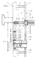
- the fitting according to the first embodiment according to FIGS. 1-7 which cannot be assigned to a door, has an elongated outer door plate 1 and a congruent inner door plate 2. Both can be connected to one another by means of two fastening screws 3 which penetrate the end regions of the inner door plate 2 and which extend from the rear of the outer door plate 1 engage outgoing threaded bushes 4.
- the latter consist of hardened material, have a thread on the outside and are screwed into an unillustrated internal thread of the outer door plate 1.
- the outer door plate 1 has an actuating handle 5 firmly connected to it.
- a threaded bushing 8 is screwed into a rear threaded bore 7 just below the connection point between the actuating handle 5 and the outer door plate 1, which, with a thread-free section, projects beyond the rear surface 1 'of the outer door plate by a few millimeters.
- the threaded sleeve 8 is in turn provided with an internal thread 9 and serves to receive a threaded pin 10 which is located at the free end of a presser pin 11 which is square in cross section. The latter extends beyond the inner door plate 2 and engages in a cross-sectionally adapted square opening 12 of an inner door handle 13, which is connected to the handle pin 11 in a known manner by means of a transverse pin 14.
- the inside door handle 13 in turn forms a bearing neck 15 which is rotatably arranged in a bearing bush 16 of the inside door plate 2.
- the outer door plate 1 is equipped with an oval opening 17 in plan such that its greatest length runs in the longitudinal direction of the outer door plate 1. With the formation of a step 18, the opening 17 continues into an opening area 17 ′ which is enlarged in cross section. The wall thereof runs parallel to that of the opening 17.
- a plate 19 lies in the shape of the opening 17.
- a collar 20 which is equipped with the same material and whose outline shape corresponds to that of the opening area 17 '.
- a spring body 21 comprising the plate 19 and consisting of elastic material, which exerts a load on the plate 19 in the direction of the door plate verder surface.
- the plate 19 inserted into the opening 17 can be turned in its plane, namely around the turning axis W which is perpendicular to the stop surface of the outer door plate 1. This means that both the narrow edges and the longitudinal edges the opening 17 and the plate 19 have the same distance from the turning axis W.
- a chamber 22 is incorporated into it to partially accommodate a profile locking cylinder 23.
- the chamber 22 is composed of a chamber space 25 comprising the circular-cylindrical locking cylinder core region 24 and two radially lying, chamber free spaces 26, 27 extending in the longitudinal center plane of the outer door plate 1, one of which in each case receives the profile cylinder flange 28 in a form-fitting manner.
- the profile cylinder flange 28 extends in the chamber free space 27.
- the profile locking cylinder 23 is connected to the plate 19 in the inserted position.
- grub screws 29 leading into the chamber free space 27.
- Two threaded bores 30, each lying in a common horizontal plane, are assigned to the chamber free spaces 26, 27.
- the grub screws 29 are then assigned only to the chamber space used in order to connect the profile locking cylinder 23 to the plate 19 to form a fixed structural unit.
- the aforementioned threaded bores 30 are machined beyond the collar 20 in the plate 19, so that the grub screws 29 are covered by the spring body 21 in the installed position of the plate 19.
- the chamber space 25 is designed to have a smaller diameter compared to the lock cylinder core area 24 and extends into the plate 19 by a larger amount than the chamber free spaces 26, 27.
- the chamber room 25 sits down with a gradation 31 into a smaller-diameter key insertion opening 32.
- a rotatable protective disk 33 made of particularly resistant material is stored in the chamber space 25 comprising the cylinder core region 24 in front of the facing end face of the profile locking cylinder 23 in the chamber space 25.
- a key insertion slot 34 is provided, which is aligned with the key channel (not shown) of the cylinder core 23 'of the profile locking cylinder 23.
- the protective disk 33 is supported by a rotatably arranged ring 35 which fills the annular gap between the chamber space 25 and the lock cylinder core region 24.
- This has a passage slot 36 for the profile cylinder flange 28, which can be brought into alignment with the chamber free spaces 26, 27. According to the installation position of the plate 19 in FIGS. 1-3, the passage slot 36 is aligned with the chamber free space 27.
- the corresponding end face of the profile locking cylinder 23 supports the plate 19 in such a way that its front side is flush with or slightly protrudes from that of the outside door plate 1.
- the opposite end of the profile locking cylinder 23 passes through a cross-section-adapted recess 37 of a frame 38.
- the latter can be inserted into a frame 39 from the rear of the inner door plate 2.
- the frame 38 is also provided with a rear, circumferential collar 40, which dips into a larger cross-sectional area 39 'of the frame 39.
- the rear surface thereof is supported on the facing door surface. In this position also aligns the front of the frame 38 with the front surface of the inner door plate.
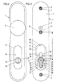
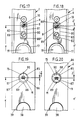
- FIG. 6 show that the recess 37 adapted to the outline shape of the profile locking cylinder 23 is located in the lower region of the frame 38.
- This frame 38 is used when the distance dimension x between the press mandrel 11 and the axis of rotation D of the cylinder core should be 92 mm.
- a surrounding compensating sleeve 41 is assigned to the handle pin 11, so that the handle pin 11 lies in the square opening of a corresponding nut of the mortise lock E, filling the shape.
- Mortise locks with a spacing of 92 mm usually have a square opening, which is larger than that of mortise locks with a spacing of 72 mm.
- the plate 19 must be turned through 180 ° in its plane and into the opening in this turned position before the fitting is installed 17 to use. Due to the offset of the axis of rotation D of the cylinder core to the transverse center plane of the plate or the turning axis W, after turning the plate 19, the axis of rotation D is closer to the square mandrel 11 than in the first installation position described above, in which the distance dimension was 92 mm.
- the profile lock cylinder 23 Before inserting the plate 19 in the turned position in the opening 17, however, the profile lock cylinder 23 is installed so that its profile cylinder flange 28 enters the chamber space 26 to fill the form. Likewise, the grub screws 29 are screwed into the threaded holes 30 opening into the chamber free space 26, capturing the profile locking cylinder 23 to the plate 19. In order to be able to use the profile locking cylinder 23, it is also necessary to close the ring 35 by 180 ° turn so that its passage slot 36 is aligned with the chamber clearance 26.
- a frame 42 which is identical in its outer shape to the frame 38 is to be inserted into the surround 39 of the inner door plate 2.
- This frame 42 is provided with a recess 43 which is offset upwards by the difference between the two distance dimensions x, y.
- the nut of the mortise lock E ' is generally provided with a square opening of smaller cross section, which is matched to that of the handle pin 11.
- the compensating sleeve 41 is not required.
- a corresponding offset of the chamber 22 to the turning axis W bridges a difference of 20 mm between the two distances by appropriate installation of the plate 19. It is understandable that differently dimensioned distance dimensions, such as are available in different countries, relocate another offset of the chamber 22 to the turning axis W.
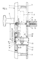
- the fitting also has an elongated outer door plate 44, which, in contrast to that the first embodiment is designed trough-shaped by a peripheral outer edge 45. Threaded bushings 47 directed inwards from the end regions of the trough base 46 for receiving fastening screws (not illustrated) which connect the inside door plate to the outside door plate.
- the outer door shield 44 has a handle 48 that is firmly connected to it on the outside.
- a nut 49 lying on the inside of the tub is used to fix the handle 48, and the handle neck 51 is screwed onto a threaded extension 50 passing through the tub 46.
- the thread extension 50 forms an internal thread and serves to receive a press mandrel, not shown.
- the trough bottom 46 of the outer door plate 44 is provided with an opening 52 which is elongated in plan, the greatest length of which likewise runs in the longitudinal direction of the outer door plate 44.
- the opening 52 there is a plate 54 fitted with a collar 53 that is equipped with the same material.
- the plate 54 can be turned in its plane around the turning axis W running perpendicular to the stop surface of the outer door plate 44.
- the collar 53 of the plate 54 is supported directly on the inner surface of the tub floor 46.
- the narrow edges 55 of the collar 53 lie against mutually facing flats 56 of screw-in sleeves 57, which start from the trough base 46 in the same material, but end at a distance from the stop face of the outer door plate 44.
- the collar 53 is lined with a spacer frame 58. Its frame opening 59 is chosen so large that the plate 54 can pass through it in a shape-fitting manner.
- spacer frame 58 slightly projects beyond one end of the screw-in sleeves 57, the flats 56 of which also lie flush against the narrow edges of the spacer frame 58.
- Tensioning screws 61 engaging in the internal thread 60 of the screwing-in bushes clamp the collar 53 against the trough bottom 46 via the spacing frame 58. This is done via the heads 61 'of the tensioning screws 61 which protrude with an edge region over the flats 56 of the screw-in bushings and with press their rear surface against the spacer frame 58, cf. 11 and 12 in particular. It can also be seen from these figures that the heads 61 'of the tensioning screws 61 do not protrude beyond the stop surface of the outer door plate 44.
- the plate protrudes over the front surface of the outer door plate 46.
- a chamber 62 is incorporated into this for receiving the corresponding front end of the profile locking cylinder 23 shown in broken lines.
- This chamber 62 is also composed of a chamber space 63 comprising the circular cylindrical locking cylinder core area 24 and two chamber free spaces 64, 65 lying radially to it and extending in the longitudinal center plane of the outer door shield 44.
- a chamber space 63 comprising the circular cylindrical locking cylinder core area 24 and two chamber free spaces 64, 65 lying radially to it and extending in the longitudinal center plane of the outer door shield 44.
- One of these accommodates the profile cylinder flange 28 in a form-fitting manner.
- the profile cylinder flange 28 is located in the chamber free space 65.
- a threaded bore 66 is used which is arranged centrally to the chamber free spaces 64, 65 and penetrates the plate 54 over its entire thickness Chamber clearances 64, 65, on the other hand, end at a short distance in front of the front of the plate 54.
- a bushing 67 with an external thread is rotatably seated in the chamber space 63 designed as a threaded bore 66.
- a thread pitch of 1 mm is selected.
- Resistant material is used for the sleeve 67 and also for the plate 54.
- the length of the sleeve 67 is slightly less than the total thickness of the door outer plate.
- a bore 68 is machined, which extends only over a partial length of the sleeve. With the formation of a step 69, the bore 68 merges into a bore section 70 of smaller diameter.
- the wall of the sleeve 67 is provided with a receiving slot 71 which is open at the edge and extends from the rear end of the sleeve and extends only over a partial length thereof.
- the width of the receiving slot 71 corresponds to the width of the chamber free spaces 64, 65 or that of the profile cylinder flange 28.
- a spacer sleeve 72 inserted into the bore 68 positively surrounds the circular-cylindrical locking cylinder core region 24.
- the spacer sleeve 72 is pressed into the clamp seat or glued to the sleeve 67, so that they form a coherent, rotatable structural unit.
- a radial slot 73 of the same is aligned with the receiving slot 71 of the sleeve 67.
- the aforementioned spacer sleeve 72 extends with its inner end up to a cylinder core protective disk 74 accommodated in the sleeve 67.
- the protective disk 74 which is made of hard-drilling material, has a smaller-diameter section 75, which is located in the bore section 70 of the sleeve 67 is rotatably supported.
- the section 75 continues into a larger-diameter collar 76, the diameter of which corresponds to the bushing bore 68.
- the protective disk 74 forms a receiving recess 77 for the protrusion of the cylinder core 23 'over the corresponding end of the lock cylinder.
- the protective disk 74 is equipped with a correspondingly large radial slot 78.
- a distance dimension x of 92 mm between the press mandrel and the axis of rotation D of the cylinder core 23 ' is realized.
- a distance dimension y according to FIG. 13 can be set by rotating the plate 54 in its plane around the turning axis W by 180 °. It is understandable that the clamping screws 61 have to be loosened for this purpose.
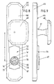
- a recess 80 extending in the longitudinal direction in the longitudinal direction is machined in the rear of the door outer plate 1.
- This is composed of the lower section 80 'and the subsequent flatter section 80''. At least the bottom of the flatter section 80 'runs parallel to the stop surface 1' of the outer door plate 1.
- a carriage 81 lies on the bottom of the flatter section 80 ''. Its width corresponds to that of the recess 80.
- the length of the slide 81 is, however, chosen to be shorter. In the upper area, the slide 81 is penetrated by a threaded hole 7 ', into which the threaded bushing 8 is now screwed.
- the threaded bushing 8 is also provided with an internal thread 9 into which the threaded pin 10 of the presser pin 11 is immersed. From Figure 16 it can also be seen that the threaded bushing 8 protrudes into the deeper section 80 'of the recess 80 such that the slide 81 - seen in the longitudinal direction of the outer door plate - has a play which is at least as great as the length difference between the recess 80 and the slide 81.
- An elongated hole 82 is machined in the slide 81 below the threaded bore 7 '. This is designed in such a way that it can accommodate the head of a countersunk screw 83. Its shaft engages in a threaded hole 84 in the outer door plate 1.
- the position of the slide 81 can be fixed by means of this countersunk screw 83. According to FIG. 16, the position of the slide 81 is selected so that the distance between the handle mandrel axis and the cylinder core axis of rotation D is 92 mm.
- the inner door handle 13 protrudes with its bearing neck 15 into the bore 85 of a bearing bush 86.
- the bearing bush bore 85 is arranged eccentrically to the center of the bearing bush M. In the exemplary embodiment, the eccentricity is one millimeter.
- the bearing bush 86 is rotatably seated in a receiving bore 87 of the inner door plate 2.
- the bearing bush 86 On the outer circumference, the bearing bush 86 carries a longitudinal web 88 which, according to FIG. 19, extends into a starting bore 87 Recess 89 engages. The latter extends at the level of the longitudinal axis of the inner door plate 2. A noticeable locking of the bearing bush 86 is achieved through this recess 89.
- a further recess 90 is provided in a diametrical opposite to the recess 89.
- the longitudinal web 88 engages in this when the bearing bush 86 is rotated by 180 °.
- the distance dimension is 92 mm. If the same is to be reduced to 90 mm, the countersunk screw 83 must be loosened on the outside door plate 1 before the same and the slide 81 displaced in the direction of the cylinder core axis of rotation D. The carriage displacement is limited in that the countersunk screw 83 acts on the corresponding transverse edge of the recess 80. Then the carriage 81 has traveled a distance of z equal to 2 mm. There is then a distance dimension of x 'between the handle mandrel axis of rotation D and the cylinder core axis of rotation, ie 90 mm, cf. Fig. 18. So that the carriage 81 remains in this set position, the countersunk screw 83 must be brought into the clamping position.
- the bearing bush 86 of the inner door plate 2 is to be turned through 180 °. Since the eccentricity is 1 mm, it corresponds to z-half. After 180 ° rotation, the handle mandrel axis of rotation has moved z equal to 2 mm in the direction of the cylinder core axis of rotation, realizing the distance dimension x ', which is 90 mm, cf. Fig. 20.
- This process described above can also be carried out when the distance between the handle mandrel axis of rotation and the cylinder core axis of rotation is 72 mm. This makes it possible to change the distance from 72 mm to 70 mm to reduce. It is therefore possible to implement four possible spacing measures using one and the same fitting.
Landscapes
- Hinges (AREA)
- Lock And Its Accessories (AREA)
- Supports Or Holders For Household Use (AREA)
- Support Devices For Sliding Doors (AREA)
- Joining Of Corner Units Of Frames Or Wings (AREA)
- Mutual Connection Of Rods And Tubes (AREA)
- Clamps And Clips (AREA)
Priority Applications (5)
| Application Number | Priority Date | Filing Date | Title |
|---|---|---|---|
| DE9016768U DE9016768U1 (de) | 1990-08-03 | 1990-12-12 | Beschlag für mit Einsteckschlössern und Schließzylindern ausgerüstete Türen |
| DE9116761U DE9116761U1 (de) | 1990-02-10 | 1991-02-08 | Beschlag für mit Einsteckschlössern und Profil-Schließzylindern ausgerüstete Türen |
| DE91101720T DE59100410D1 (de) | 1990-02-10 | 1991-02-08 | Beschlag fuer mit einsteckschloessern und profil-schliesszylindern ausgeruestete tueren. |
| EP19910101720 EP0442384B1 (fr) | 1990-02-10 | 1991-02-08 | Ferrure pour portes équipées de serrure encastrée à cylindre profilé |
| AT91101720T ATE95269T1 (de) | 1990-02-10 | 1991-02-08 | Beschlag fuer mit einsteckschloessern und profilschliesszylindern ausgeruestete tueren. |
Applications Claiming Priority (4)
| Application Number | Priority Date | Filing Date | Title |
|---|---|---|---|
| DE4004113 | 1990-02-10 | ||
| DE4004113 | 1990-02-10 | ||
| DE4014581A DE4014581A1 (de) | 1990-02-10 | 1990-05-07 | Beschlag fuer mit einsteckschloessern und profil-schliesszylindern ausgeruestete tueren |
| DE4014581 | 1990-05-07 |
Publications (3)
| Publication Number | Publication Date |
|---|---|
| EP0442047A2 true EP0442047A2 (fr) | 1991-08-21 |
| EP0442047A3 EP0442047A3 (en) | 1991-12-11 |
| EP0442047B1 EP0442047B1 (fr) | 1994-05-18 |
Family
ID=25889965
Family Applications (1)
| Application Number | Title | Priority Date | Filing Date |
|---|---|---|---|
| EP90121932A Expired - Lifetime EP0442047B1 (fr) | 1990-02-10 | 1990-11-16 | Ferrure pour portes équipées de serrure encastrée à cylindre profilé |
Country Status (3)
| Country | Link |
|---|---|
| EP (1) | EP0442047B1 (fr) |
| AT (1) | ATE105906T1 (fr) |
| DE (3) | DE4014581A1 (fr) |
Cited By (11)
| Publication number | Priority date | Publication date | Assignee | Title |
|---|---|---|---|---|
| EP0592385A1 (fr) * | 1992-10-06 | 1994-04-13 | Roto Frank Eisenwarenfabrik Aktiengesellschaft | Ferrure de poignée de porte |
| EP0694661A1 (fr) * | 1994-07-07 | 1996-01-31 | Hans Dieter Niemann | Rosette de sécurité pour serrure cylindrique |
| US5489655A (en) * | 1993-07-26 | 1996-02-06 | General Electric Company | Thermosetting resin compositions with low shrinkage |
| US5762884A (en) * | 1995-09-08 | 1998-06-09 | Mitsubishi Jukogyo Kabushiki Kaisha | Flue gas treating system |
| EP1070812A1 (fr) * | 1999-07-23 | 2001-01-24 | Bricard Societe Anonyme | Serrure comprenant un dispositif de protection contre les tentatives d'effraction |
| NL1019991C2 (nl) * | 2002-02-18 | 2003-08-19 | Comari Holland B V | Veiligheidsbeslag voor een deurslot. |
| WO2008003977A1 (fr) * | 2006-07-07 | 2008-01-10 | Peter Heeley | Ensemble de plaquettes pour loquet de porte |
| FR2929975A1 (fr) * | 2008-04-11 | 2009-10-16 | Dt 2000 Sa Sa | Dispositif de poignees de porte avec modules de trous de fonctions interchangeables |
| ITMC20090222A1 (it) * | 2009-10-27 | 2011-04-28 | Alessandro Cirilli | Attrezzatura modulare per la realizzazione di una maniglia per porte ed infissi, associata o meno ad un rispettivo chiavistello di sicurezza. |
| GB2616059A (en) * | 2022-02-25 | 2023-08-30 | Gretsch Unitas Ltd | A Door Handle Arrangement |
| AU2024203506B2 (en) * | 2018-05-30 | 2026-02-12 | Assa Abloy New Zealand Limited | A lock assembly |
Families Citing this family (3)
| Publication number | Priority date | Publication date | Assignee | Title |
|---|---|---|---|---|
| DE19754767C2 (de) * | 1997-11-28 | 2002-06-20 | Obst Gmbh | Kernschutzbeschlag für Profil-Schließzylinder |
| GB0005753D0 (en) * | 2000-03-11 | 2000-05-03 | Banham Patent Locks Ltd | Lock |
| DE10256724B4 (de) * | 2002-12-05 | 2016-08-18 | Friedrich Kurz Gmbh | Beschlag für mit Schließanlagen ausgerüsteten Türen |
Family Cites Families (3)
| Publication number | Priority date | Publication date | Assignee | Title |
|---|---|---|---|---|
| DE3234512C2 (de) * | 1982-09-17 | 1985-07-18 | Jans, Franz Werner, 6050 Offenbach | Türschild für ein Türschloß |
| DE3741228A1 (de) * | 1987-09-23 | 1989-04-13 | Melchert Beschlaege | Beschlag fuer tueren oder dergleichen |
| DE8914633U1 (de) * | 1989-12-08 | 1990-02-08 | Ikon AG Präzisionstechnik, 1000 Berlin | Schutzbeschlag |
-
1990
- 1990-05-07 DE DE4014581A patent/DE4014581A1/de not_active Withdrawn
- 1990-11-16 AT AT90121932T patent/ATE105906T1/de not_active IP Right Cessation
- 1990-11-16 EP EP90121932A patent/EP0442047B1/fr not_active Expired - Lifetime
- 1990-11-16 DE DE59005750T patent/DE59005750D1/de not_active Expired - Fee Related
-
1991
- 1991-02-08 DE DE91101720T patent/DE59100410D1/de not_active Expired - Fee Related
Cited By (14)
| Publication number | Priority date | Publication date | Assignee | Title |
|---|---|---|---|---|
| EP0592385A1 (fr) * | 1992-10-06 | 1994-04-13 | Roto Frank Eisenwarenfabrik Aktiengesellschaft | Ferrure de poignée de porte |
| US5489655A (en) * | 1993-07-26 | 1996-02-06 | General Electric Company | Thermosetting resin compositions with low shrinkage |
| EP0694661A1 (fr) * | 1994-07-07 | 1996-01-31 | Hans Dieter Niemann | Rosette de sécurité pour serrure cylindrique |
| US5762884A (en) * | 1995-09-08 | 1998-06-09 | Mitsubishi Jukogyo Kabushiki Kaisha | Flue gas treating system |
| EP1070812A1 (fr) * | 1999-07-23 | 2001-01-24 | Bricard Societe Anonyme | Serrure comprenant un dispositif de protection contre les tentatives d'effraction |
| FR2796667A1 (fr) * | 1999-07-23 | 2001-01-26 | Bricard Sa | Serrure comportant un dispositif de protection contre les tentatives d'effraction |
| NL1019991C2 (nl) * | 2002-02-18 | 2003-08-19 | Comari Holland B V | Veiligheidsbeslag voor een deurslot. |
| WO2008003977A1 (fr) * | 2006-07-07 | 2008-01-10 | Peter Heeley | Ensemble de plaquettes pour loquet de porte |
| GB2453893A (en) * | 2006-07-07 | 2009-04-22 | Peter Heeley | Door latch face plate assembly |
| GB2453893B (en) * | 2006-07-07 | 2011-08-03 | Peter Heeley | Door latch face plate assembly |
| FR2929975A1 (fr) * | 2008-04-11 | 2009-10-16 | Dt 2000 Sa Sa | Dispositif de poignees de porte avec modules de trous de fonctions interchangeables |
| ITMC20090222A1 (it) * | 2009-10-27 | 2011-04-28 | Alessandro Cirilli | Attrezzatura modulare per la realizzazione di una maniglia per porte ed infissi, associata o meno ad un rispettivo chiavistello di sicurezza. |
| AU2024203506B2 (en) * | 2018-05-30 | 2026-02-12 | Assa Abloy New Zealand Limited | A lock assembly |
| GB2616059A (en) * | 2022-02-25 | 2023-08-30 | Gretsch Unitas Ltd | A Door Handle Arrangement |
Also Published As
| Publication number | Publication date |
|---|---|
| ATE105906T1 (de) | 1994-06-15 |
| DE59005750D1 (de) | 1994-06-23 |
| EP0442047B1 (fr) | 1994-05-18 |
| DE4014581A1 (de) | 1991-08-14 |
| EP0442047A3 (en) | 1991-12-11 |
| DE59100410D1 (de) | 1993-11-04 |
Similar Documents
| Publication | Publication Date | Title |
|---|---|---|
| EP0442047B1 (fr) | Ferrure pour portes équipées de serrure encastrée à cylindre profilé | |
| CH672939A5 (fr) | ||
| EP2284335A2 (fr) | Dispositif de palier et rosette formant une partie d'une garniture de poignée | |
| WO1999054574A1 (fr) | Systeme de securite a encastrer et clef pour serrure de securite | |
| EP0442384B1 (fr) | Ferrure pour portes équipées de serrure encastrée à cylindre profilé | |
| DE3229732C1 (de) | Scharnier | |
| EP0495361B1 (fr) | Ferrure pour portes équipées de serrures encastrées à cylindre profilé | |
| DE102008036151A1 (de) | Scharnierband mit einer Unterkonstruktion zur Befestigung an einem Türblatt | |
| DE8717477U1 (de) | Beschlag für Türen o.dgl. | |
| DE102020128079B4 (de) | Beschlag mit variablen Befestigungselementen | |
| DE3042207A1 (de) | Verstellbares tuerband | |
| DE8008675U1 (de) | Mit einem schliesszylinder ausgeruestetes bauelement | |
| CH690450A5 (de) | Zylinderschloss. | |
| DE9116761U1 (de) | Beschlag für mit Einsteckschlössern und Profil-Schließzylindern ausgerüstete Türen | |
| DE3305209C3 (de) | Türschloß | |
| DE8209457U1 (de) | Tuerdruecker-garnitur mit holzdrueckern | |
| EP0118113A2 (fr) | Serrure avec dispositif d'entrebâillement | |
| DE9016768U1 (de) | Beschlag für mit Einsteckschlössern und Schließzylindern ausgerüstete Türen | |
| DE9410913U1 (de) | Sicherheitsrosette für Schließzylinder | |
| EP0430185A2 (fr) | Dispositif de fixation de carré de poignée pour l'actionnement d'une porte ou similaire | |
| AT393865B (de) | Drueckergarnitur | |
| DE3506870A1 (de) | Tuerverschluss mit hebelfoermiger versenkbarer handhabe, insbesondere an schaltschranktueren | |
| DE8717418U1 (de) | Beschlag für Türen o.dgl. | |
| DE19947864A1 (de) | An einer Zarge, einem Stock od. dgl. befestigbarer Beschlag | |
| EP1320654A1 (fr) | Bande de porte |
Legal Events
| Date | Code | Title | Description |
|---|---|---|---|
| PUAI | Public reference made under article 153(3) epc to a published international application that has entered the european phase |
Free format text: ORIGINAL CODE: 0009012 |
|
| AK | Designated contracting states |
Kind code of ref document: A2 Designated state(s): AT BE CH DE FR GB IT LI NL |
|
| PUAL | Search report despatched |
Free format text: ORIGINAL CODE: 0009013 |
|
| AK | Designated contracting states |
Kind code of ref document: A3 Designated state(s): AT BE CH DE FR GB IT LI NL |
|
| 17P | Request for examination filed |
Effective date: 19920212 |
|
| 17Q | First examination report despatched |
Effective date: 19930803 |
|
| GRAA | (expected) grant |
Free format text: ORIGINAL CODE: 0009210 |
|
| AK | Designated contracting states |
Kind code of ref document: B1 Designated state(s): AT BE CH DE FR GB IT LI NL |
|
| PG25 | Lapsed in a contracting state [announced via postgrant information from national office to epo] |
Ref country code: IT Free format text: LAPSE BECAUSE OF FAILURE TO SUBMIT A TRANSLATION OF THE DESCRIPTION OR TO PAY THE FEE WITHIN THE PRESCRIBED TIME-LIMIT;WARNING: LAPSES OF ITALIAN PATENTS WITH EFFECTIVE DATE BEFORE 2007 MAY HAVE OCCURRED AT ANY TIME BEFORE 2007. THE CORRECT EFFECTIVE DATE MAY BE DIFFERENT FROM THE ONE RECORDED. Effective date: 19940518 Ref country code: GB Effective date: 19940518 |
|
| REF | Corresponds to: |
Ref document number: 105906 Country of ref document: AT Date of ref document: 19940615 Kind code of ref document: T |
|
| REF | Corresponds to: |
Ref document number: 59005750 Country of ref document: DE Date of ref document: 19940623 |
|
| ET | Fr: translation filed | ||
| GBV | Gb: ep patent (uk) treated as always having been void in accordance with gb section 77(7)/1977 [no translation filed] |
Effective date: 19940518 |
|
| PLBE | No opposition filed within time limit |
Free format text: ORIGINAL CODE: 0009261 |
|
| STAA | Information on the status of an ep patent application or granted ep patent |
Free format text: STATUS: NO OPPOSITION FILED WITHIN TIME LIMIT |
|
| 26N | No opposition filed | ||
| PGFP | Annual fee paid to national office [announced via postgrant information from national office to epo] |
Ref country code: FR Payment date: 19960926 Year of fee payment: 7 |
|
| PGFP | Annual fee paid to national office [announced via postgrant information from national office to epo] |
Ref country code: AT Payment date: 19971016 Year of fee payment: 8 Ref country code: CH Payment date: 19971016 Year of fee payment: 8 |
|
| PG25 | Lapsed in a contracting state [announced via postgrant information from national office to epo] |
Ref country code: FR Free format text: THE PATENT HAS BEEN ANNULLED BY A DECISION OF A NATIONAL AUTHORITY Effective date: 19971130 |
|
| REG | Reference to a national code |
Ref country code: FR Ref legal event code: ST |
|
| PG25 | Lapsed in a contracting state [announced via postgrant information from national office to epo] |
Ref country code: AT Free format text: LAPSE BECAUSE OF NON-PAYMENT OF DUE FEES Effective date: 19981116 |
|
| PG25 | Lapsed in a contracting state [announced via postgrant information from national office to epo] |
Ref country code: LI Free format text: LAPSE BECAUSE OF NON-PAYMENT OF DUE FEES Effective date: 19981130 Ref country code: CH Free format text: LAPSE BECAUSE OF NON-PAYMENT OF DUE FEES Effective date: 19981130 |
|
| REG | Reference to a national code |
Ref country code: CH Ref legal event code: PL |
|
| PGFP | Annual fee paid to national office [announced via postgrant information from national office to epo] |
Ref country code: NL Payment date: 20051130 Year of fee payment: 16 |
|
| PGFP | Annual fee paid to national office [announced via postgrant information from national office to epo] |
Ref country code: BE Payment date: 20051220 Year of fee payment: 16 |
|
| PG25 | Lapsed in a contracting state [announced via postgrant information from national office to epo] |
Ref country code: BE Free format text: LAPSE BECAUSE OF NON-PAYMENT OF DUE FEES Effective date: 20061130 |
|
| PGFP | Annual fee paid to national office [announced via postgrant information from national office to epo] |
Ref country code: DE Payment date: 20070531 Year of fee payment: 17 |
|
| PG25 | Lapsed in a contracting state [announced via postgrant information from national office to epo] |
Ref country code: NL Free format text: LAPSE BECAUSE OF NON-PAYMENT OF DUE FEES Effective date: 20070601 |
|
| NLV4 | Nl: lapsed or anulled due to non-payment of the annual fee |
Effective date: 20070601 |
|
| BERE | Be: lapsed |
Owner name: *ASSA RUKO SICHERHEITSSYSTEME G.M.B.H. Effective date: 20061130 |
|
| PG25 | Lapsed in a contracting state [announced via postgrant information from national office to epo] |
Ref country code: DE Free format text: LAPSE BECAUSE OF NON-PAYMENT OF DUE FEES Effective date: 20080603 |