EP0442047B1 - Ferrure pour portes équipées de serrure encastrée à cylindre profilé - Google Patents
Ferrure pour portes équipées de serrure encastrée à cylindre profilé Download PDFInfo
- Publication number
- EP0442047B1 EP0442047B1 EP90121932A EP90121932A EP0442047B1 EP 0442047 B1 EP0442047 B1 EP 0442047B1 EP 90121932 A EP90121932 A EP 90121932A EP 90121932 A EP90121932 A EP 90121932A EP 0442047 B1 EP0442047 B1 EP 0442047B1
- Authority
- EP
- European Patent Office
- Prior art keywords
- plate
- cylinder
- door plate
- furniture according
- profile
- Prior art date
- Legal status (The legal status is an assumption and is not a legal conclusion. Google has not performed a legal analysis and makes no representation as to the accuracy of the status listed.)
- Expired - Lifetime
Links
- 238000003780 insertion Methods 0.000 claims abstract description 7
- 230000001681 protective effect Effects 0.000 claims description 17
- 239000000463 material Substances 0.000 claims description 9
- 230000037431 insertion Effects 0.000 claims description 6
- 238000006073 displacement reaction Methods 0.000 claims description 2
- 230000002093 peripheral effect Effects 0.000 claims description 2
- 230000013011 mating Effects 0.000 claims 1
- 230000002441 reversible effect Effects 0.000 abstract description 5
- 238000009434 installation Methods 0.000 description 22
- 125000006850 spacer group Chemical group 0.000 description 19
- 230000015572 biosynthetic process Effects 0.000 description 3
- 230000001427 coherent effect Effects 0.000 description 2
- 238000005553 drilling Methods 0.000 description 2
- 230000002349 favourable effect Effects 0.000 description 2
- 238000004519 manufacturing process Methods 0.000 description 2
- 230000007423 decrease Effects 0.000 description 1
- 238000011161 development Methods 0.000 description 1
- 230000018109 developmental process Effects 0.000 description 1
- 239000013013 elastic material Substances 0.000 description 1
- 230000001771 impaired effect Effects 0.000 description 1
- 238000000034 method Methods 0.000 description 1
- 230000003287 optical effect Effects 0.000 description 1
- 230000006641 stabilisation Effects 0.000 description 1
- 238000011105 stabilization Methods 0.000 description 1
Images


Classifications
-
- E—FIXED CONSTRUCTIONS
- E05—LOCKS; KEYS; WINDOW OR DOOR FITTINGS; SAFES
- E05B—LOCKS; ACCESSORIES THEREFOR; HANDCUFFS
- E05B15/00—Other details of locks; Parts for engagement by bolts of fastening devices
- E05B15/02—Striking-plates; Keepers; Bolt staples; Escutcheons
-
- E—FIXED CONSTRUCTIONS
- E05—LOCKS; KEYS; WINDOW OR DOOR FITTINGS; SAFES
- E05B—LOCKS; ACCESSORIES THEREFOR; HANDCUFFS
- E05B15/00—Other details of locks; Parts for engagement by bolts of fastening devices
- E05B15/16—Use of special materials for parts of locks
- E05B15/1614—Use of special materials for parts of locks of hard materials, to prevent drilling
- E05B2015/1628—Free-rotating protecting covers or discs
-
- E—FIXED CONSTRUCTIONS
- E05—LOCKS; KEYS; WINDOW OR DOOR FITTINGS; SAFES
- E05B—LOCKS; ACCESSORIES THEREFOR; HANDCUFFS
- E05B63/00—Locks or fastenings with special structural characteristics
- E05B63/0056—Locks with adjustable or exchangeable lock parts
Definitions
- the invention relates to a fitting for mortise equipped with mortise locks and profile lock cylinders according to the preamble of the main claim.
- Such a fitting is known from DE-GM 87 10 518, the plate forming a circumferential collar at the rear being inserted into the shape-matched opening of the outer door plate.
- a distance between the handle mandrel and the cylinder core axis of rotation of 72 or 92 mm can be realized.
- the distance dimension of 92 mm is selected for front doors or apartment doors, while a dimension of 72 mm is preferred for interior doors. It is therefore necessary, depending on the distance, to manufacture, store and sell appropriate door signs combined with increased effort in this regard.
- the older EP application 431 717 shows a version in which the outer door plate can be changed to different spacing dimensions between the handle mandrel and the cylinder core axis of rotation in that an opening is provided in the outer door plate, which is designed in a geometrically similar shape to the profile locking cylinder, so that the locking cylinder core area is different Heights can be moved. If he sits closest to the door handle, the profile flange in the actual door outer plate is no longer gripped on the side; there are free spaces between the side wall of the profile cylinder flange and the side walls of the opening in the outer door plate. These free spaces are covered by a thin cover that can be placed on the outside of the door plate from the outside and screwed on from the back. The shape is such that you can turn it over.
- the object of the invention is based on the design of a fitting of the type in question in a technically simple manner so that it can accommodate the profile locking cylinder in two different positions in the correct position.
- the profile cylinder flange protrudes into one of the two chamber spaces, while the lock cylinder core area is always in the chamber space surrounding it.
- a chamber free space therefore remains unused. However, this is not visible from the outside of the door's outside plate. Only the key insertion opening remains free, so that the usual appearance of the fitting is not is changed.
- the outer door sign should be set to the standardized spacing dimensions of 72 and 92 mm, the turning axis of the plate extends on the middle of the difference in distance between the two possible spacing dimensions.
- the configuration according to the invention even permits a rotatable protective disk made of hardened material and having the key insertion slot. This can be used with advantage in the chamber space comprising the cylinder core area.
- the disc in particular prevents the cylinder core from being torn out according to the corkscrew principle. It also serves as protection against drilling. So that the protective disk remains in its position, it is supported by the ring which is rotatably arranged in the chamber space. Depending on the installation position or the selected spacing between the pusher mandrel and the axis of rotation of the cylinder core, this is to be turned so that the annular passage slot is in alignment with the corresponding chamber clearance and allows the cylinder flange to pass through. If only a single inner door plate is to be used despite two installation positions, two lock cylinder frames are assigned to it.
- One frame can then be inserted in the one installation position of the plate and the other frame in the other installation position of the plate in the associated version of the inner door plate.
- the application area of the fitting is further optimized by the fact that the plate carries a threaded bushing equipped with a cylinder core protective disk and is assigned to a spacer frame. This can be converted from a relining position to the collar of the plate into a relining position of the plate. In this way, it is possible in a simple manner to compensate for certain thickness tolerances of the door, so that there is an overall extensive adjustment of the fitting.
- the distance frame fulfills the task of one Coarse adjustment, while the fine adjustment is carried out via the threaded bush.
- the cylinder core protective disk can be brought in close proximity to the cylinder core face and fulfills a supporting function there.
- the protective disk and sleeve are preferably designed so that the end face of the profile locking cylinder, which is concentric with the cylinder core end face, is supported on the protective disk.
- the spacer frame is brought to the collar in the relining position when the thickness of the door decreases.
- the backfeeding position is selected when the door is thicker. Coarse and fine adjustment are accordingly adjusted to one another in such a way that after the fitting has been struck, it also has an optically favorable appearance.
- Fitting plate, plate and spacer frame form a coherent structural unit in that the plate or spacer frame is overlapped by clamping screws, the heads of which protrude beyond the outer surface of screw-in sleeves of the fitting plate.
- This unit is manufactured before the fitting is installed. This proves to be easier when mounting the fitting plate.
- the heads of the clamping screws do not protrude beyond the stop surface of the fitting plate, they only press the assembly consisting of a plate and spacer frame against the inside of the fitting plate.
- This measure also combines the fitting with all the individual parts to form a fixed structural unit, so that there are also advantages in terms of storage or transport.
- the thickness of the frame and the thread adjustment area are coordinated so that the frame thickness is smaller than the thread adjustment area of the bush.
- distance between the handle mandrel and the cylinder core axis of 70 or 90 can be achieved in that the outer door plate has a movable in its longitudinal direction, lockable carriage for receiving the handle mandrel. After the plate has been appropriately turned over, the slide must then be moved and then fixed to achieve the desired distance. It is not necessary to replace components. This also applies to the bearing of the inside door handle receiving the handle mandrel. A change only requires turning the bearing bush, whereby due to the eccentric arrangement of the bearing bush bore, the change in distance from the axis of rotation of the cylinder core takes place. Should z. B. the distance measure vary by 2 mm, an eccentricity of one millimeter must be carried out. In order to change the distance dimension by 2 mm, the bearing bush must be turned 180 °. The rotary positions of the bearing bush can be indicated by locking means.
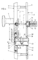
- the fitting according to the first embodiment according to FIGS. 1-7 which cannot be assigned to a door, has an elongated outer door plate 1 and a congruent inner door plate 2. Both can be connected to one another by means of two fastening screws 3 which penetrate the end regions of the inner door plate 2 and which are in from the rear of the outer door plate 1 engage outgoing threaded bushes 4.
- the latter consist of hardened material, have a thread on the outside and are screwed into an unillustrated internal thread of the outer door plate 1.
- the outer door plate 1 carries an actuating handle 5 firmly connected to it.
- a threaded bushing 8 is screwed into a rear threaded bore 7 just below the connection point between the actuating handle 5 and the outer door plate 1, which, with a thread-free section, projects a few millimeters beyond the rear surface 1 'of the outer door plate.
- the threaded bushing 8 is in turn provided with an internal thread 9 and serves to receive a threaded pin 10 which is located at the free end of a presser mandrel 11 which is square in cross section. The latter extends beyond the inner door plate 2 and engages in a cross-sectionally adapted square opening 12 of an inner door handle 13, which is connected to the handle pin 11 in a known manner by means of a transverse pin 14.
- the inside door handle 13 in turn forms a bearing neck 15 which is rotatably arranged in a bearing bush 16 of the inside door plate 2.
- the outer door plate 1 is equipped with an oval opening 17 in plan such that its greatest length runs in the longitudinal direction of the outer door plate 1. With the formation of a step 18, the opening 17 continues into an opening area 17 ′ which is enlarged in cross section. The wall thereof runs parallel to that of the opening 17.
- a plate 19 lies in the shape of the opening 17. At the rear, the same is provided with a collar 20 which is of uniform material and whose outline shape corresponds to that of the opening area 17 '. Between collar 20 and step 18 there extends a spring body 21 comprising plate 19 and made of elastic material, which exerts a load on plate 19 against the direction of the front face of the door plate.
- the plate 19 inserted into the opening 17 is reversible in its plane, namely around the turning axis W which is perpendicular to the stop surface of the outer door plate 1. This means that both the narrow edges and the longitudinal edges the opening 17 and the plate 19 have the same distance from the turning axis W.
- a chamber 22 is incorporated into it to partially accommodate a profile locking cylinder 23.
- the chamber 22 is composed of a chamber space 25 comprising the circular-cylindrical locking cylinder core region 24 and two radially located chamber free spaces 26, 27 extending in the longitudinal center plane of the outer door plate 1, one of which in each case receives the profile cylinder flange 28 in a form-fitting manner.
- the profile cylinder flange 28 extends in the chamber free space 27.
- the profile locking cylinder 23 is connected to the plate 19 in the inserted position.
- grub screws 29 opening into the chamber free space 27.
- Two threaded bores 30, each lying in a common horizontal plane, are assigned to the chamber free spaces 26, 27.
- the grub screws 29 are then assigned only to the chamber space used in order to connect the profile locking cylinder 23 to the plate 19 to form a fixed structural unit.
- the aforementioned threaded bores 30 are machined into the plate 19 beyond the collar 20, so that the grub screws 29 are covered by the spring body 21 in the installed position of the plate 19.
- the chamber space 25 is designed to have a smaller diameter compared to the lock cylinder core region 24 and extends into the plate 19 by a larger amount than the chamber free spaces 26, 27.
- the chamber room 25 sits down with the formation of a gradation 31 into a smaller-diameter key insertion opening 32.
- a rotatable protective disk 33 made of particularly resistant material is stored in the chamber space 25 comprising the cylinder core region 24 in front of the facing end face of the profile locking cylinder 23 in the chamber space 25.
- a key insertion slot 34 is provided, which is aligned with the key channel (not shown) of the cylinder core 23 'of the profile locking cylinder 23.
- the protective disk 33 is supported by a rotatably arranged ring 35 which fills the annular gap between the chamber space 25 and the lock cylinder core region 24.
- This has a passage slot 36 for the profile cylinder flange 28 which can be brought into alignment with the chamber free spaces 26, 27. According to the installation position of the plate 19 in FIGS. 1-3, the passage slot 36 is aligned with the chamber free space 27.
- the corresponding end face of the profile locking cylinder 23 supports the plate 19 in such a way that its front side is flush with or slightly protrudes from that of the outside door plate 1.
- the opposite end of the profile locking cylinder 23 passes through a cross-section-adapted recess 37 of a frame 38.
- the latter can be inserted into a frame 39 from the rear of the inner door plate 2.
- the frame 38 is also provided with a rear, circumferential collar 40, which dips into a larger cross-sectional area 39 'of the frame 39.
- the rear surface thereof is supported on the facing door surface. In this position also aligns the front of the frame 38 with the front surface of the inner door plate.
- FIG. 6 show that the recess 37 adapted to the outline shape of the profile locking cylinder 23 is located in the lower region of the frame 38.
- This frame 38 is used when the distance dimension x between the press mandrel 11 and the axis of rotation D of the cylinder core should be 92 mm.
- a compensating sleeve 41 is assigned to the handle pin 11, so that the handle pin 11 lies in the square opening of a corresponding nut of the mortise lock E to fill the shape.
- Mortise locks with a distance of 92 mm usually have a square opening, which is larger than that of mortise locks with a distance of 72 mm.
- the plate 19 must be turned through 180 ° in its plane and into the opening in this turned position before the fitting is installed 17 to use. Due to the offset of the axis of rotation D of the cylinder core to the transverse central plane of the plate or the turning axis W, after turning the plate 19, the axis of rotation D is closer to the square mandrel 11 than in the first installation position described above, in which the distance dimension was 92 mm.
- the profile lock cylinder 23 Before inserting the plate 19 in the turned position in the opening 17, however, the profile lock cylinder 23 is installed so that its profile cylinder flange 28 enters the chamber space 26 to fill the form. Likewise, the grub screws 29 are to be screwed into the threaded holes 30 opening into the chamber free space 26, capturing the profile locking cylinder 23 to the plate 19. In order to be able to use the profile locking cylinder 23, it is also necessary to close the ring 35 by 180 ° turn so that its passage slot 36 is aligned with the chamber clearance 26.
- a frame 42 which is identical in its outer shape to the frame 38 is to be inserted into the surround 39 of the inner door plate 2.
- This frame 42 is provided with a recess 43 which is offset upwards by the difference between the two distance dimensions x, y.
- the nut of the mortise lock E ' is generally provided with a square opening of smaller cross section, which is adapted to that of the handle pin 11.
- the compensating sleeve 41 is not required.
- a corresponding offset of the chamber 22 to the turning axis W bridges a difference of 20 mm between the two distances by appropriate installation of the plate 19. It is understandable that differently dimensioned spacing dimensions, as they exist in different countries, relocate a different offset of the chamber 22 to the turning axis W.
- the fitting also has an elongated outer door plate 44, which in contrast to that the first embodiment is designed trough-shaped by a peripheral outer edge 45. Threaded bushings 47 directed inwards from the end of the trough base 46 for receiving fastening screws (not illustrated) which connect the inside door plate to the outside door plate.
- the outside door shield 44 has a handle 48 that is firmly connected to it on the outside.
- a nut 49 which is located on the inside of the tub and is screwed onto a threaded extension 50 passing through the tub bottom 46, is used to fix the handle 48 to the handle neck 51.
- the thread extension 50 forms an internal thread and serves to receive a press mandrel, not shown.
- the trough base 46 of the door outer plate 44 is provided with an opening 52 which is elongated in plan, the greatest length of which likewise runs in the longitudinal direction of the door outer plate 44.
- the opening 52 there is a plate 54 fitted with a collar 53 that is equipped with the same material.
- the plate 54 is reversible in its plane around the turning axis W running perpendicular to the stop surface of the outer door plate 44.
- the collar 53 of the plate 54 is supported directly on the inner surface of the tub floor 46.
- the narrow edges 55 of the collar 53 lie against mutually facing flats 56 of screw-in sleeves 57, which start from the trough base 46 in the same material, but end at a distance from the stop face of the door outer plate 44.
- the collar 53 is back-lined by a spacer frame 58. Its frame opening 59 is chosen so large that the plate 54 can pass through it in a shape-fitting manner.
- spacer frame 58 slightly projects beyond one end of the screw-in sleeves 57, the flats 56 of which also lie flush against the narrow edges of the spacer frame 58.
- Tensioning screws 61 engaging in the internal thread 60 of the screwing-in bushes clamp the collar 53 against the trough bottom 46 via the spacing frame 58. This is done via the heads 61 'of the tensioning screws 61, which protrude with an edge region over the flats 56 of the screw-in bushings and with press their rear surface against the spacer frame 58, cf. 11 and 12 in particular. It can also be seen from these figures that the heads 61 'of the tensioning screws 61 do not protrude beyond the stop surface of the outer door plate 44.
- the plate protrudes over the front surface of the outer door plate 46.
- a chamber 62 for receiving the corresponding front end of the profile locking cylinder 23 shown in broken lines is incorporated into this.
- This chamber 62 is also composed of a chamber space 63 comprising the circular cylindrical locking cylinder core region 24 and two chamber free spaces 64, 65 lying radially to it and extending in the longitudinal center plane of the outer door shield 44.
- One of these in each case accommodates the profile cylinder flange 28 in a form-fitting manner.
- the profile cylinder flange 28 is located in the chamber free space 65.
- a threaded bore 66 is used which is arranged centrally to the chamber free spaces 64, 65 and penetrates the plate 54 over its entire thickness Chamber clearances 64, 65, on the other hand, end at a short distance in front of the front of the plate 54.
- a bush 67 provided with an external thread is rotatably seated in the chamber space 63 designed as a threaded bore 66.
- a thread pitch of 1 mm is selected.
- Resistant material is used for the sleeve 67 and also for the plate 54.
- the length of the sleeve 67 is slightly less than the total thickness of the door outer plate.
- a bore 68 is machined, which extends only over a partial length of the sleeve. With the formation of a step 69, the bore 68 merges into a bore section 70 of smaller diameter.
- the wall of the sleeve 67 is provided with a receiving slot 71 which is open at the edge and extends from the rear end of the sleeve and extends only over a partial length thereof.
- the width of the receiving slot 71 corresponds to the width of the chamber free spaces 64, 65 or that of the profile cylinder flange 28.
- a spacer sleeve 72 inserted into the bore 68 positively surrounds the circular-cylindrical locking cylinder core region 24.
- the spacer sleeve 72 is pressed into the clamp seat or glued to the sleeve 67, so that they form a coherent, rotatable structural unit.
- a radial slot 73 of the same is aligned with the receiving slot 71 of the sleeve 67.
- the aforesaid spacer sleeve 72 protrudes with its inner end up to a cylinder core protective disk 74 accommodated in the sleeve 67.
- the protective disk 74 which is made of hard-drilling material, has a smaller-diameter section 75, which is located in the bore section 70 of the sleeve 67 rotatably.
- the section 75 continues into a larger diameter collar 76, the diameter of which corresponds to the bushing bore 68.
- the protective disk 74 forms a receiving recess 77 for the protrusion of the cylinder core 23 'over the corresponding end surface of the lock cylinder.
- the protective disk 74 is equipped with a correspondingly large radial slot 78.
- a distance dimension x of 92 mm is realized between the press mandrel and the axis of rotation D of the cylinder core 23 '.
- a distance dimension y according to FIG. 13 can be set by rotating the plate 54 in its plane around the turning axis W by 180 °. It is understandable that the clamping screws 61 have to be loosened for this purpose.
- a recess 80 running in the longitudinal direction is machined in the longitudinal direction on the rear side of the outer door plate 1.
- This is composed of the lower section 80 'and the subsequent flatter section 80''. At least the bottom of the flatter section 80 'runs parallel to the stop surface 1' of the outer door plate 1.
- a slide 81 lies on the bottom of the flatter section 80 ''. Its width corresponds to that of the recess 80. The length of the slide 81 is, however, chosen to be shorter. In the upper area, the slide 81 is penetrated by a threaded hole 7 ', into which the threaded bushing 8 is now screwed.
- the threaded bushing 8 is also provided with an internal thread 9 into which the threaded pin 10 of the presser pin 11 is immersed. From Figure 16 it can also be seen that the threaded bushing 8 protrudes into the deeper section 80 'of the recess 80 in such a way that the slide 81 - seen in the longitudinal direction of the outer door plate - has a play which is at least as great as the length difference between the recess 80 and the slide 81.
- An elongated hole 82 is machined below the threaded hole 7 'in the slide 81. This is designed in such a way that it can accommodate the head of a countersunk screw 83. Its shaft engages in a threaded hole 84 in the outer door plate 1.
- the position of the slide 81 can be fixed by means of this countersunk screw 83. According to FIG. 16, the position of the slide 81 is selected so that the distance between the pusher mandrel axis and the cylinder core axis of rotation D is 92 mm.
- the inner door handle 13 protrudes with its bearing neck 15 into the bore 85 of a bearing bush 86.
- the bearing bush bore 85 is arranged eccentrically to the center of the bearing bush M. In the exemplary embodiment, the eccentricity is one millimeter.
- the bearing bush 86 is rotatably seated in a receiving bore 87 in the inner door key 2.
- the bearing bush 86 On the outer circumference, the bearing bush 86 carries a longitudinal web 88 which, according to FIG. 19, extends into a starting bore 87 Recess 89 engages. The latter extends at the level of the longitudinal axis of the inner door plate 2. A noticeable locking of the bearing bush 86 is achieved through this recess 89.
- a further recess 90 is provided in a diametrically opposed position to the recess 89.
- the longitudinal web 88 engages in this when the bearing bush 86 is rotated by 180 °.
- the distance dimension is 92 mm. If the same is to be reduced to 90 mm, the countersunk screw 83 must be loosened on the outside door plate 1 before the same and the slide 81 displaced in the direction of the cylinder core axis of rotation D. The carriage displacement is limited in that the countersunk screw 83 acts on the corresponding transverse edge of the recess 80. Then the carriage 81 has traveled a distance of z equal to 2 mm. There is then a distance dimension of x 'between the handle mandrel axis of rotation D and the cylinder core axis of rotation, ie 90 mm, cf. Fig. 18. So that the carriage 81 remains in this set position, the countersunk screw 83 must be brought into the clamping position.
- the bearing bush 86 of the inner door plate 2 is to be turned through 180 °. Since the eccentricity is 1 mm, it corresponds to z-half. After 180 ° rotation, the handle mandrel axis of rotation has moved z equal to 2 mm in the direction of the cylinder core axis of rotation, realizing the distance dimension x ', which is 90 mm, cf. Fig. 20.
- This process described above can also be carried out if the distance between the handle mandrel axis of rotation and the cylinder core axis of rotation is 72 mm. This makes it possible to change the distance from 72 mm to 70 mm to reduce. Four possible spacing measures can therefore be realized by means of one and the same fitting.
Landscapes
- Hinges (AREA)
- Lock And Its Accessories (AREA)
- Supports Or Holders For Household Use (AREA)
- Support Devices For Sliding Doors (AREA)
- Joining Of Corner Units Of Frames Or Wings (AREA)
- Mutual Connection Of Rods And Tubes (AREA)
- Clamps And Clips (AREA)
Claims (10)
- Ferrure pour portes équipées de serrures à larder (E, E'), pouvant être actionnée par une poignée de porte, et de cylindres de fermeture profilés (23), avec un panneau extérieur de porte (1, 44) pouvant être modifié pour s'adapter à différents entraxes (x) entre le mandrin de poignée (11) et l'axe de rotation (D) du fouillot, et qui présente, inséré dans une ouverture (17, 52), avec ajustement de forme, une garniture, entourant la zone du fouillot (24) du cylindre de fermeture et l'appendice de cylindre de fermeture (28) en s'en écartant radialement, de telle façon que le fouillot de cylindre (23') portant le canal de clé soit décalé par rapport au plan médian transversal de la garniture, l'ouverture (17) se prolongeant, en constituant un étagement (18), en une zone d'ouverture (17') à section transversale agrandie, caractérisée par la combinaison des caractéristiques suivantes :a. la garniture est maintenue, à titre de plaque (19, 54) insérée de l'arrière dans le panneau extérieur de porte,a1. plaque présentant une collerette formée d'un seul tenant dans la même matière et dont la forme du contour correspond à celle de la zone d'ouverture (17'),b. la plaque comporte, en partant de l'espace de chambre (25, respectivement 63) entourant la zone de fouillot (24) du cylindre de fermeture, deux espaces libres de chambre (26; 27, respectivement 64, 65), quib1. recouvrent la face frontale du cylindre de fermeture profilé, tout en laissant libre une ouverture d'enfichage de clé, et dontb2. chaque fois l'un reçoit l'appendice (28) du cylindre profilé, l'autre restant libre dans la direction de l'espace libre (26 ou 27, respectivement 64 ou 65) présentant le mandrin de poignée.
- Ferrure selon la revendication 1, caractérisée en ce qu'une rondelle de protection (33, respectivement 74), susceptible de pouvoir tourner et présentant la fente d'introduction de clé (34 respectivement 78), est disposée dans l'espace de chambre (25, 63) entourant la zone de fouillot de cylindre (24).
- Ferrure selon une ou plusieurs des revendications précédentes, caractérisée en ce que la rondelle de protection (33, 74) est soutenue au moyen d'une bague (35, respectivement 72) disposée de façon à pouvoir tourner, présentant une fente de passage (36, respectivement 73), destinée à l'appendice de cylindre profilé (28) et pouvant être placée en position alignée par rapport aux espaces libres de chambre (26, 27, respectivement 64, 65),
- Ferrure selon une ou plusieurs des revendications précédentes, caractérisée en ce qu'à un panneau intérieur de porte (2) sont associé des cadres de cylindre de fermeture (38, 42), de telle manière qu'un premier cadre (38) puisse être inséré dans une position de montage de la plaque (19) et que le deuxième cadre (42) puisse être inséré dans l'autre position de montage de la plaque (19), dans une monture (39) afférente du panneau intérieur de porte (2).
- Ferrure selon une ou plusieurs des revendications précédentes, caractérisée en ce que la plaque (54) porte une douille (67) déplaçable par un filetage et équipée d'une rondelle de protection de fouillot (74) et est associée à un cadre d'espacement (58), pouvant être converti, d'une position de garnissage sous-jacent par rapport à la collerette (53) de la plaque (54) à une position de garnissage arrière de la plaque (54).
- Ferrure selon une ou plusieurs des revendications précédentes, caractérisée en ce que la plaque (54) ou le cadre d'espacement (58) sont saisis par le dessus par des vis de serrage (61), dont les têtes (60') font saillies au-dessus de la surface d'enveloppe de douilles à vissage de vis (57) du panneau extérieur de porte (44).
- Ferrure selon une ou plusieurs des revendications précédentes, caractérisée en ce que l'épaisseur du cadre d'espacement (58) est quelque peu inférieure à la plage de réglage par vissage de la douille (67).
- Ferrure selon une ou plusieurs des revendications précédentes, caractérisée en ce que les douilles à vissage de vis (57) appuient, par des méplats (56) tournés les uns vers les autres, sur les petits côtés du cadre d'espacement (58) et de la collerette (53).
- Ferrure selon une ou plusieurs des revendications précédentes, caractérisée en ce que le panneau extérieur de porte (1) comporte un coulisseau (81), déplaçable en direction longitudinale et pouvant être bloqué, en vue de recevoir le mandrin de poignée (11).
- Ferrure selon une ou plusieurs des revendications précédentes, caractérisée en ce que le panneau intérieur de porte (2) reçoit dans une douille de palier (86) le col de palier (15) d'une poignée intérieure de porte (13), l'alésage de douille de palier (85) étant disposé excentré par rapport au centre (M) de douille de palier.
Priority Applications (5)
| Application Number | Priority Date | Filing Date | Title |
|---|---|---|---|
| DE9016768U DE9016768U1 (de) | 1990-08-03 | 1990-12-12 | Beschlag für mit Einsteckschlössern und Schließzylindern ausgerüstete Türen |
| DE9116761U DE9116761U1 (de) | 1990-02-10 | 1991-02-08 | Beschlag für mit Einsteckschlössern und Profil-Schließzylindern ausgerüstete Türen |
| DE91101720T DE59100410D1 (de) | 1990-02-10 | 1991-02-08 | Beschlag fuer mit einsteckschloessern und profil-schliesszylindern ausgeruestete tueren. |
| EP19910101720 EP0442384B1 (fr) | 1990-02-10 | 1991-02-08 | Ferrure pour portes équipées de serrure encastrée à cylindre profilé |
| AT91101720T ATE95269T1 (de) | 1990-02-10 | 1991-02-08 | Beschlag fuer mit einsteckschloessern und profilschliesszylindern ausgeruestete tueren. |
Applications Claiming Priority (4)
| Application Number | Priority Date | Filing Date | Title |
|---|---|---|---|
| DE4004113 | 1990-02-10 | ||
| DE4004113 | 1990-02-10 | ||
| DE4014581A DE4014581A1 (de) | 1990-02-10 | 1990-05-07 | Beschlag fuer mit einsteckschloessern und profil-schliesszylindern ausgeruestete tueren |
| DE4014581 | 1990-05-07 |
Publications (3)
| Publication Number | Publication Date |
|---|---|
| EP0442047A2 EP0442047A2 (fr) | 1991-08-21 |
| EP0442047A3 EP0442047A3 (en) | 1991-12-11 |
| EP0442047B1 true EP0442047B1 (fr) | 1994-05-18 |
Family
ID=25889965
Family Applications (1)
| Application Number | Title | Priority Date | Filing Date |
|---|---|---|---|
| EP90121932A Expired - Lifetime EP0442047B1 (fr) | 1990-02-10 | 1990-11-16 | Ferrure pour portes équipées de serrure encastrée à cylindre profilé |
Country Status (3)
| Country | Link |
|---|---|
| EP (1) | EP0442047B1 (fr) |
| AT (1) | ATE105906T1 (fr) |
| DE (3) | DE4014581A1 (fr) |
Families Citing this family (14)
| Publication number | Priority date | Publication date | Assignee | Title |
|---|---|---|---|---|
| AT398453B (de) * | 1992-10-06 | 1994-12-27 | Roto Frank Eisenwaren | Türdrückerbeschlagsgarnitur |
| US5489655A (en) * | 1993-07-26 | 1996-02-06 | General Electric Company | Thermosetting resin compositions with low shrinkage |
| DE9410913U1 (de) * | 1994-07-07 | 1995-11-09 | Niemann, Hans Dieter, 50169 Kerpen | Sicherheitsrosette für Schließzylinder |
| JP3015718B2 (ja) * | 1995-09-08 | 2000-03-06 | 三菱重工業株式会社 | 排煙処理システム |
| DE19754767C2 (de) * | 1997-11-28 | 2002-06-20 | Obst Gmbh | Kernschutzbeschlag für Profil-Schließzylinder |
| FR2796667B1 (fr) * | 1999-07-23 | 2002-12-13 | Bricard Sa | Serrure comportant un dispositif de protection contre les tentatives d'effraction |
| GB0005753D0 (en) * | 2000-03-11 | 2000-05-03 | Banham Patent Locks Ltd | Lock |
| NL1019991C2 (nl) * | 2002-02-18 | 2003-08-19 | Comari Holland B V | Veiligheidsbeslag voor een deurslot. |
| DE10256724B4 (de) * | 2002-12-05 | 2016-08-18 | Friedrich Kurz Gmbh | Beschlag für mit Schließanlagen ausgerüsteten Türen |
| GB0613587D0 (en) * | 2006-07-07 | 2006-08-16 | Heeley Peter | Door latch face plate assembly |
| FR2929975A1 (fr) * | 2008-04-11 | 2009-10-16 | Dt 2000 Sa Sa | Dispositif de poignees de porte avec modules de trous de fonctions interchangeables |
| IT1395997B1 (it) * | 2009-10-27 | 2012-11-09 | Cirilli | Attrezzatura modulare per la realizzazione di una maniglia per porte ed infissi, associata o meno ad un rispettivo chiavistello di sicurezza |
| AU2019203732A1 (en) * | 2018-05-30 | 2019-12-19 | Assa Abloy New Zealand Limited | A lock assembly |
| GB2616059A (en) * | 2022-02-25 | 2023-08-30 | Gretsch Unitas Ltd | A Door Handle Arrangement |
Family Cites Families (3)
| Publication number | Priority date | Publication date | Assignee | Title |
|---|---|---|---|---|
| DE3234512C2 (de) * | 1982-09-17 | 1985-07-18 | Jans, Franz Werner, 6050 Offenbach | Türschild für ein Türschloß |
| DE3741228A1 (de) * | 1987-09-23 | 1989-04-13 | Melchert Beschlaege | Beschlag fuer tueren oder dergleichen |
| DE8914633U1 (de) * | 1989-12-08 | 1990-02-08 | Ikon AG Präzisionstechnik, 1000 Berlin | Schutzbeschlag |
-
1990
- 1990-05-07 DE DE4014581A patent/DE4014581A1/de not_active Withdrawn
- 1990-11-16 AT AT90121932T patent/ATE105906T1/de not_active IP Right Cessation
- 1990-11-16 EP EP90121932A patent/EP0442047B1/fr not_active Expired - Lifetime
- 1990-11-16 DE DE59005750T patent/DE59005750D1/de not_active Expired - Fee Related
-
1991
- 1991-02-08 DE DE91101720T patent/DE59100410D1/de not_active Expired - Fee Related
Also Published As
| Publication number | Publication date |
|---|---|
| ATE105906T1 (de) | 1994-06-15 |
| DE59005750D1 (de) | 1994-06-23 |
| DE4014581A1 (de) | 1991-08-14 |
| EP0442047A3 (en) | 1991-12-11 |
| EP0442047A2 (fr) | 1991-08-21 |
| DE59100410D1 (de) | 1993-11-04 |
Similar Documents
| Publication | Publication Date | Title |
|---|---|---|
| EP0442047B1 (fr) | Ferrure pour portes équipées de serrure encastrée à cylindre profilé | |
| CH672939A5 (fr) | ||
| EP1040245B1 (fr) | Tourniquet pour portes, volets ou similaires a paroi epaisse | |
| EP0442384B1 (fr) | Ferrure pour portes équipées de serrure encastrée à cylindre profilé | |
| EP0495361B1 (fr) | Ferrure pour portes équipées de serrures encastrées à cylindre profilé | |
| EP2284342A2 (fr) | Charnière avec surface d'appui encochée | |
| DE8717477U1 (de) | Beschlag für Türen o.dgl. | |
| DE3042207A1 (de) | Verstellbares tuerband | |
| EP0930411B1 (fr) | Penture de porte ou de fenêtre | |
| DE9116761U1 (de) | Beschlag für mit Einsteckschlössern und Profil-Schließzylindern ausgerüstete Türen | |
| DE8008675U1 (de) | Mit einem schliesszylinder ausgeruestetes bauelement | |
| DE3741967C2 (fr) | ||
| DE3305209C3 (de) | Türschloß | |
| AT393865B (de) | Drueckergarnitur | |
| DE8209457U1 (de) | Tuerdruecker-garnitur mit holzdrueckern | |
| DE9410913U1 (de) | Sicherheitsrosette für Schließzylinder | |
| DE9016768U1 (de) | Beschlag für mit Einsteckschlössern und Schließzylindern ausgerüstete Türen | |
| EP0118113A2 (fr) | Serrure avec dispositif d'entrebâillement | |
| EP0430185A2 (fr) | Dispositif de fixation de carré de poignée pour l'actionnement d'une porte ou similaire | |
| DE8717418U1 (de) | Beschlag für Türen o.dgl. | |
| EP0943757B1 (fr) | Rosette de sécurité pour serrure cylindrique | |
| DE69409929T2 (de) | Scharnier | |
| DE3506870A1 (de) | Tuerverschluss mit hebelfoermiger versenkbarer handhabe, insbesondere an schaltschranktueren | |
| DE4405360A1 (de) | Beschlag zur schwenkbaren Befestigung des Flügels einer Tür oder eines Fensters an einem Rahmen | |
| DE29719468U1 (de) | Tür- oder Fensterband |
Legal Events
| Date | Code | Title | Description |
|---|---|---|---|
| PUAI | Public reference made under article 153(3) epc to a published international application that has entered the european phase |
Free format text: ORIGINAL CODE: 0009012 |
|
| AK | Designated contracting states |
Kind code of ref document: A2 Designated state(s): AT BE CH DE FR GB IT LI NL |
|
| PUAL | Search report despatched |
Free format text: ORIGINAL CODE: 0009013 |
|
| AK | Designated contracting states |
Kind code of ref document: A3 Designated state(s): AT BE CH DE FR GB IT LI NL |
|
| 17P | Request for examination filed |
Effective date: 19920212 |
|
| 17Q | First examination report despatched |
Effective date: 19930803 |
|
| GRAA | (expected) grant |
Free format text: ORIGINAL CODE: 0009210 |
|
| AK | Designated contracting states |
Kind code of ref document: B1 Designated state(s): AT BE CH DE FR GB IT LI NL |
|
| PG25 | Lapsed in a contracting state [announced via postgrant information from national office to epo] |
Ref country code: IT Free format text: LAPSE BECAUSE OF FAILURE TO SUBMIT A TRANSLATION OF THE DESCRIPTION OR TO PAY THE FEE WITHIN THE PRESCRIBED TIME-LIMIT;WARNING: LAPSES OF ITALIAN PATENTS WITH EFFECTIVE DATE BEFORE 2007 MAY HAVE OCCURRED AT ANY TIME BEFORE 2007. THE CORRECT EFFECTIVE DATE MAY BE DIFFERENT FROM THE ONE RECORDED. Effective date: 19940518 Ref country code: GB Effective date: 19940518 |
|
| REF | Corresponds to: |
Ref document number: 105906 Country of ref document: AT Date of ref document: 19940615 Kind code of ref document: T |
|
| REF | Corresponds to: |
Ref document number: 59005750 Country of ref document: DE Date of ref document: 19940623 |
|
| ET | Fr: translation filed | ||
| GBV | Gb: ep patent (uk) treated as always having been void in accordance with gb section 77(7)/1977 [no translation filed] |
Effective date: 19940518 |
|
| PLBE | No opposition filed within time limit |
Free format text: ORIGINAL CODE: 0009261 |
|
| STAA | Information on the status of an ep patent application or granted ep patent |
Free format text: STATUS: NO OPPOSITION FILED WITHIN TIME LIMIT |
|
| 26N | No opposition filed | ||
| PGFP | Annual fee paid to national office [announced via postgrant information from national office to epo] |
Ref country code: FR Payment date: 19960926 Year of fee payment: 7 |
|
| PGFP | Annual fee paid to national office [announced via postgrant information from national office to epo] |
Ref country code: AT Payment date: 19971016 Year of fee payment: 8 Ref country code: CH Payment date: 19971016 Year of fee payment: 8 |
|
| PG25 | Lapsed in a contracting state [announced via postgrant information from national office to epo] |
Ref country code: FR Free format text: THE PATENT HAS BEEN ANNULLED BY A DECISION OF A NATIONAL AUTHORITY Effective date: 19971130 |
|
| REG | Reference to a national code |
Ref country code: FR Ref legal event code: ST |
|
| PG25 | Lapsed in a contracting state [announced via postgrant information from national office to epo] |
Ref country code: AT Free format text: LAPSE BECAUSE OF NON-PAYMENT OF DUE FEES Effective date: 19981116 |
|
| PG25 | Lapsed in a contracting state [announced via postgrant information from national office to epo] |
Ref country code: LI Free format text: LAPSE BECAUSE OF NON-PAYMENT OF DUE FEES Effective date: 19981130 Ref country code: CH Free format text: LAPSE BECAUSE OF NON-PAYMENT OF DUE FEES Effective date: 19981130 |
|
| REG | Reference to a national code |
Ref country code: CH Ref legal event code: PL |
|
| PGFP | Annual fee paid to national office [announced via postgrant information from national office to epo] |
Ref country code: NL Payment date: 20051130 Year of fee payment: 16 |
|
| PGFP | Annual fee paid to national office [announced via postgrant information from national office to epo] |
Ref country code: BE Payment date: 20051220 Year of fee payment: 16 |
|
| PG25 | Lapsed in a contracting state [announced via postgrant information from national office to epo] |
Ref country code: BE Free format text: LAPSE BECAUSE OF NON-PAYMENT OF DUE FEES Effective date: 20061130 |
|
| PGFP | Annual fee paid to national office [announced via postgrant information from national office to epo] |
Ref country code: DE Payment date: 20070531 Year of fee payment: 17 |
|
| PG25 | Lapsed in a contracting state [announced via postgrant information from national office to epo] |
Ref country code: NL Free format text: LAPSE BECAUSE OF NON-PAYMENT OF DUE FEES Effective date: 20070601 |
|
| NLV4 | Nl: lapsed or anulled due to non-payment of the annual fee |
Effective date: 20070601 |
|
| BERE | Be: lapsed |
Owner name: *ASSA RUKO SICHERHEITSSYSTEME G.M.B.H. Effective date: 20061130 |
|
| PG25 | Lapsed in a contracting state [announced via postgrant information from national office to epo] |
Ref country code: DE Free format text: LAPSE BECAUSE OF NON-PAYMENT OF DUE FEES Effective date: 20080603 |