EP0442090A1 - Système de freinage hydraulique à double circuit - Google Patents
Système de freinage hydraulique à double circuit Download PDFInfo
- Publication number
- EP0442090A1 EP0442090A1 EP19900124340 EP90124340A EP0442090A1 EP 0442090 A1 EP0442090 A1 EP 0442090A1 EP 19900124340 EP19900124340 EP 19900124340 EP 90124340 A EP90124340 A EP 90124340A EP 0442090 A1 EP0442090 A1 EP 0442090A1
- Authority
- EP
- European Patent Office
- Prior art keywords
- brake
- valve
- wheel
- pressure
- pump
- Prior art date
- Legal status (The legal status is an assumption and is not a legal conclusion. Google has not performed a legal analysis and makes no representation as to the accuracy of the status listed.)
- Withdrawn
Links
- 239000012530 fluid Substances 0.000 claims description 18
- 230000000903 blocking effect Effects 0.000 claims description 3
- 230000001419 dependent effect Effects 0.000 claims description 2
- 238000011144 upstream manufacturing Methods 0.000 claims 1
- 238000009987 spinning Methods 0.000 abstract description 5
- 238000010586 diagram Methods 0.000 description 4
- 230000005284 excitation Effects 0.000 description 2
- 238000000034 method Methods 0.000 description 2
- 238000011161 development Methods 0.000 description 1
- 230000018109 developmental process Effects 0.000 description 1
- 230000010354 integration Effects 0.000 description 1
Images

Classifications
-
- B—PERFORMING OPERATIONS; TRANSPORTING
- B60—VEHICLES IN GENERAL
- B60T—VEHICLE BRAKE CONTROL SYSTEMS OR PARTS THEREOF; BRAKE CONTROL SYSTEMS OR PARTS THEREOF, IN GENERAL; ARRANGEMENT OF BRAKING ELEMENTS ON VEHICLES IN GENERAL; PORTABLE DEVICES FOR PREVENTING UNWANTED MOVEMENT OF VEHICLES; VEHICLE MODIFICATIONS TO FACILITATE COOLING OF BRAKES
- B60T8/00—Arrangements for adjusting wheel-braking force to meet varying vehicular or ground-surface conditions, e.g. limiting or varying distribution of braking force
- B60T8/32—Arrangements for adjusting wheel-braking force to meet varying vehicular or ground-surface conditions, e.g. limiting or varying distribution of braking force responsive to a speed condition, e.g. acceleration or deceleration
- B60T8/34—Arrangements for adjusting wheel-braking force to meet varying vehicular or ground-surface conditions, e.g. limiting or varying distribution of braking force responsive to a speed condition, e.g. acceleration or deceleration having a fluid pressure regulator responsive to a speed condition
- B60T8/48—Arrangements for adjusting wheel-braking force to meet varying vehicular or ground-surface conditions, e.g. limiting or varying distribution of braking force responsive to a speed condition, e.g. acceleration or deceleration having a fluid pressure regulator responsive to a speed condition connecting the brake actuator to an alternative or additional source of fluid pressure, e.g. traction control systems
- B60T8/4809—Traction control, stability control, using both the wheel brakes and other automatic braking systems
- B60T8/4827—Traction control, stability control, using both the wheel brakes and other automatic braking systems in hydraulic brake systems
- B60T8/4863—Traction control, stability control, using both the wheel brakes and other automatic braking systems in hydraulic brake systems closed systems
- B60T8/4872—Traction control, stability control, using both the wheel brakes and other automatic braking systems in hydraulic brake systems closed systems pump-back systems
-
- B—PERFORMING OPERATIONS; TRANSPORTING
- B60—VEHICLES IN GENERAL
- B60T—VEHICLE BRAKE CONTROL SYSTEMS OR PARTS THEREOF; BRAKE CONTROL SYSTEMS OR PARTS THEREOF, IN GENERAL; ARRANGEMENT OF BRAKING ELEMENTS ON VEHICLES IN GENERAL; PORTABLE DEVICES FOR PREVENTING UNWANTED MOVEMENT OF VEHICLES; VEHICLE MODIFICATIONS TO FACILITATE COOLING OF BRAKES
- B60T8/00—Arrangements for adjusting wheel-braking force to meet varying vehicular or ground-surface conditions, e.g. limiting or varying distribution of braking force
- B60T8/32—Arrangements for adjusting wheel-braking force to meet varying vehicular or ground-surface conditions, e.g. limiting or varying distribution of braking force responsive to a speed condition, e.g. acceleration or deceleration
- B60T8/34—Arrangements for adjusting wheel-braking force to meet varying vehicular or ground-surface conditions, e.g. limiting or varying distribution of braking force responsive to a speed condition, e.g. acceleration or deceleration having a fluid pressure regulator responsive to a speed condition
- B60T8/343—Systems characterised by their lay-out
- B60T8/344—Hydraulic systems
- B60T8/348—4 Channel systems
-
- B—PERFORMING OPERATIONS; TRANSPORTING
- B60—VEHICLES IN GENERAL
- B60T—VEHICLE BRAKE CONTROL SYSTEMS OR PARTS THEREOF; BRAKE CONTROL SYSTEMS OR PARTS THEREOF, IN GENERAL; ARRANGEMENT OF BRAKING ELEMENTS ON VEHICLES IN GENERAL; PORTABLE DEVICES FOR PREVENTING UNWANTED MOVEMENT OF VEHICLES; VEHICLE MODIFICATIONS TO FACILITATE COOLING OF BRAKES
- B60T8/00—Arrangements for adjusting wheel-braking force to meet varying vehicular or ground-surface conditions, e.g. limiting or varying distribution of braking force
- B60T8/32—Arrangements for adjusting wheel-braking force to meet varying vehicular or ground-surface conditions, e.g. limiting or varying distribution of braking force responsive to a speed condition, e.g. acceleration or deceleration
- B60T8/34—Arrangements for adjusting wheel-braking force to meet varying vehicular or ground-surface conditions, e.g. limiting or varying distribution of braking force responsive to a speed condition, e.g. acceleration or deceleration having a fluid pressure regulator responsive to a speed condition
- B60T8/40—Arrangements for adjusting wheel-braking force to meet varying vehicular or ground-surface conditions, e.g. limiting or varying distribution of braking force responsive to a speed condition, e.g. acceleration or deceleration having a fluid pressure regulator responsive to a speed condition comprising an additional fluid circuit including fluid pressurising means for modifying the pressure of the braking fluid, e.g. including wheel driven pumps for detecting a speed condition, or pumps which are controlled by means independent of the braking system
- B60T8/4013—Fluid pressurising means for more than one fluid circuit, e.g. separate pump units used for hydraulic booster and anti-lock braking
-
- B—PERFORMING OPERATIONS; TRANSPORTING
- B60—VEHICLES IN GENERAL
- B60T—VEHICLE BRAKE CONTROL SYSTEMS OR PARTS THEREOF; BRAKE CONTROL SYSTEMS OR PARTS THEREOF, IN GENERAL; ARRANGEMENT OF BRAKING ELEMENTS ON VEHICLES IN GENERAL; PORTABLE DEVICES FOR PREVENTING UNWANTED MOVEMENT OF VEHICLES; VEHICLE MODIFICATIONS TO FACILITATE COOLING OF BRAKES
- B60T8/00—Arrangements for adjusting wheel-braking force to meet varying vehicular or ground-surface conditions, e.g. limiting or varying distribution of braking force
- B60T8/32—Arrangements for adjusting wheel-braking force to meet varying vehicular or ground-surface conditions, e.g. limiting or varying distribution of braking force responsive to a speed condition, e.g. acceleration or deceleration
- B60T8/34—Arrangements for adjusting wheel-braking force to meet varying vehicular or ground-surface conditions, e.g. limiting or varying distribution of braking force responsive to a speed condition, e.g. acceleration or deceleration having a fluid pressure regulator responsive to a speed condition
- B60T8/42—Arrangements for adjusting wheel-braking force to meet varying vehicular or ground-surface conditions, e.g. limiting or varying distribution of braking force responsive to a speed condition, e.g. acceleration or deceleration having a fluid pressure regulator responsive to a speed condition having expanding chambers for controlling pressure, i.e. closed systems
- B60T8/4275—Pump-back systems
Definitions
- the invention is based on a hydraulic dual-circuit brake system with a diagonal brake circuit division, anti-lock system (ABS) and traction control system (ASR) for motor vehicles, in particular cars, of the type defined in the preamble of claim 1.
- ABS anti-lock system
- ASR traction control system
- ABS anti-lock braking system
- the wheel brake cylinders are connected to the return line, with the brake fluid flowing out of the wheel brake cylinders being returned from the return pump to the master brake cylinder per brake circuit.
- All solenoid valves are controlled by an ABS control electronics in accordance with the slip detected by means of slip sensors on the wheels, the solenoid valves for the wheel brake cylinders of the two rear wheels generally being controlled together, so that the same brake pressure prevails in the rear wheels.
- Small brake fluid reservoirs are usually switched on in the return, which can temporarily hold a brake fluid volume of approx. 2 cm3 per brake circuit when the pressure is reduced.
- DE 36 33 687 A1 discloses a hydraulic two-circuit brake system with a diagonal brake circuit division, anti-lock braking system (ABS) and anti-slip control (ASR) for motor vehicles of the type mentioned at the outset, in which such a four-channel hydraulic unit is used (see FIGS. 3 and 8 there ).
- ABS anti-lock braking system
- ASR anti-slip control
- the two pressure pistons of an auxiliary brake cylinder which are designed as tandem pistons, are actuated via a piston rod by a spring accumulator, which is released when at least one drive wheel occurs when wheel slip occurs, the tensioned return spring displacing the pressure pistons.
- the two central valves are switched over either hydraulically (FIG. 3) or electrically (FIG.
- the two pressure pistons now apply brake pressure to the wheel brake cylinders of the drive wheels controlled.
- the control electronics control the control valves, whereby the spinning drive wheel is braked until it is slip-free.
- the brake fluid introduced into the wheel brake cylinder is then conveyed back into the cylinder space of the additional brake cylinder by the pump element of the return pump.
- the spring accumulator is tensioned by a low-pressure pump, which pumps brake fluid into the storage space of the spring accumulator until the spring-loaded piston has reached its end position and opens a switch in the circuit of the low-pressure pump.
- a two-circuit brake system with a brake circuit division "front-rear", an anti-lock system and a traction control system is known, in which the return pump has a total of three separate pump elements.
- Two pump elements are used to return the brake fluid from the wheel brake cylinders to the master brake cylinder in order to reduce the brake pressure during normal braking, while the third pump element ensures the brake pressure supply during traction control.
- the third pump element is connected on the input side to the brake fluid reservoir on the master brake cylinder and on the output side to a pressure reservoir.
- the brake fluid pressure built up in the pressure accumulator is applied via a 3/2-way valve with hydraulic control input to the ABS control valve designed here as a 3/2-way solenoid valve for the driven rear wheels, in such a way that this pressure is applied in the excited brake pressure reduction position of the ABS control valve is controlled in the wheel brake cylinder.
- the 3/2-way valve is switched by the brake pressure generated by the master brake cylinder, so that the connection between the pressure accumulator and the control valve is shut off.
- the control valve is switched so that the wheel brake cylinders are connected to the pressure accumulator via the 3/2-way valve.
- a 2/2-way solenoid valve is switched on between the output of the control valve and the wheel brake cylinder.
- the control electronics switch over the 2/2-way solenoid valve that is assigned to the drive wheel that shows no slip.
- the wheel brake cylinder of this drive wheel is thus decoupled from the pressure accumulator, so that the pressure build-up takes place only in the wheel brake cylinder of the slipping drive wheel.
- the hydraulic dual-circuit brake system according to the invention with the characterizing features of claim 1 has the advantage that in a dual-circuit brake system with diagonal brake circuit division, in which the drive wheels belong to different brake circuits, similar to a dual-circuit brake system with a brake circuit division "front-rear", in which the drive wheels are the same Belong to brake circuit, the brake pressure supply for ASR operation can be realized with relatively little effort.
- the third pump element of the return pump designed as a self-priming high-pressure pump, feeds directly into the wheel brake cylinders of the drive wheels in ASR operation via a pressure relief valve and the solenoid valve arrangement.
- the closed brake circuits with their well-known reliability remain untouched by the integration of the traction control system (ASR).
- the high-pressure pump preferably only generates a brake supply pressure at ASR and does not interfere with the ABS.
- ASR in a dual-circuit brake system with diagonal brake circuit distribution, in which the brake pressure is supplied via an additional brake cylinder, there are no hysteresis problems.
- the direct feeding of the brake pressure in the ASR case into the wheel brake cylinder avoids a series connection of control valves and solenoid valve arrangement with the known pressure gradient problems.
- the brake pressure supply by the high-pressure pump only with ASR is realized according to an advantageous embodiment of the invention in that an electromagnetically operated changeover valve is connected between the outlet and the inlet of the high-pressure pump, which bypasses the pressure relief valve in its deenergized basic position and only becomes effective in its energized working position leaves.
- the high-pressure pump which is also operated in ABS mode with the high-pressure switch in the basic position, delivers in unpressurized circulation and only generates the high brake pressure after switching over the switch valve with traction control.
- the solenoid valve arrangement can be realized by two 2/2-way solenoid valves or by a 3/3-way solenoid valve. In both cases, the solenoid valves are controlled by the control electronics together with the control valves assigned to the drive wheels and the changeover valve, which also switches on the electric motor for driving the high-pressure pump.
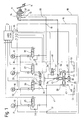
- the hydraulic dual-circuit brake system shown in the drawing in the block diagram with diagonal brake circuit division, anti-lock braking system (ABS) and traction control system (ASR), also called propulsion control, is suitable for front and rear wheel drive vehicles and is explained here using the example of a rear wheel drive passenger car.
- the wheels of the motor vehicle are labeled VL (front left) HR (rear right), HL (rear left) and VR (front right).
- the wheel brake cylinders assigned to these wheels are designated by 10.
- the wheel brake cylinders 10 of the wheels VL and HR on the one hand and the wheel brake cylinders of the wheels HL and VR on the other hand are each arranged in a brake circuit.
- the dual-circuit brake system includes, in a manner known per se, a master brake cylinder 11, with or without vacuum booster 37, which has two separate brake circuit outputs 12, 13 for connecting one of the two brake circuits and is connected to a brake fluid reservoir 14.
- a brake pedal 15 When a brake pedal 15 is actuated, an equal brake pressure is controlled in the brake circuits via the two brake circuit outputs 12, 13.
- the dual-circuit brake system also includes a four-channel hydraulic unit 16 which has two inlet channels 17, 18 and four outlet channels 21-24.
- the two inlet channels 17, 18 are connected via supply lines 19, 20 to the two brake circuit outputs 12, 13 of the master brake cylinder 11, while the wheel brake cylinders 10 are connected to the outlet channels 21 - 24 via brake lines.
- Each outlet channel 21-24 is assigned a control valve 25-28 designed as a 3/3-way solenoid valve with spring return, which is controlled by control electronics 30 in a known manner as a function of a slip sensed on the assigned wheel and thus a brake pressure dependent on the wheel slip in the associated wheel brake cylinder 10 builds.
- two control valves 25, 26 and 27, 28 are connected to an inlet duct 17 and 18 and thus belong to the same brake circuit.
- the four-channel hydraulic unit 16 also includes a return pump 29, which has two separate pump elements 43, 44, which are driven together by an electric motor 46.
- the pump elements 43 and 44 serve to return brake fluid when the brake pressure is reduced in the wheel brake cylinders 10 to the master brake cylinder 11, in each case in a brake circuit.
- the pump elements 43, 44 are each on the input side via a pump inlet valve 49 and a return line 47 or 48 Control valves 25, 26 and 27, 28 of the two brake circuits and connected on the outlet side to the associated inlet duct 17 and 18 via a pump outlet valve 50.
- Low-pressure accumulators 51 in the return lines 47, 48 are switched on to absorb the volume of brake fluid from the wheel brake cylinders 10 when the brake pressure is reduced.
- the control valves 25-28 are designed in a known manner so that in their first, non-energized position there is an unhindered passage from the inlet channel 17 or 18 to the outlet channels 21-24. In the second position, excited with half the maximum current, this passage is interrupted so that the brake pressure applied in the wheel brake cylinders 10 is kept constant. In the third position, excited with maximum current, the outlet channels 21-24, and thus the wheel brake cylinders 10, are connected to the return lines 47 and 48, the brake fluid from the wheel brake cylinders 10 being released into the low-pressure accumulator 51.
- the control valves 25, 28 assigned to the outlet channels 21, 24 for the wheel brake cylinders 10 of the non-driven wheels VL, VR are connected in parallel. For reasons of brake pressure build-up in the traction control system (ASR) to be described, these check valves are missing on the control valves 26, 27 for the drive wheels HR, HL.
- ASR traction control system
- a third pump element 45 is arranged on the return pump 29 and is driven by the electric motor 46 together with the two pump elements 43, 44.
- This is designed as a self-priming high-pressure pump and connected on the input side via a pump inlet valve 55 to the brake fluid reservoir 14 and on the outlet side via a pump outlet valve 54 and a solenoid valve arrangement 31 to the outlet channels 22, 23 for the wheel brake cylinders 10 of the drive wheels HR, HL.
- Pump inlet and Outlet valve 55, 54 of high-pressure pump 45 are connected to one another via a changeover valve 56 which is designed as a 2/2-way solenoid valve with spring return and is controlled by control electronics 30.
- the changeover valve 56 is designed so that it allows an unimpeded flow between the pump inlet and outlet valve 55, 54 in its unexcited basic position and switches on a pressure limiting valve 57 in between in its excited working position.
- This pressure relief valve 57 limits the pressure of the high pressure pump to approximately 100 bar.
- the pressure limiting valve 57 can - as shown in FIG. 1 - be integrated in the changeover valve 56 or be connected in parallel with the changeover valve 56. Then the changeover valve 56 only disconnects the connection between the valve inlet and outlet which is in the de-energized rest position.
- the solenoid valve arrangement 31 consists of two 2/2-way solenoid valves 32, 33 with spring return, one of which is assigned to an outlet channel 22 or 23 for the wheel brake cylinder 10 of the drive wheels HR and HL. From each 2/2-way solenoid valve 32 or 33, a working connection is connected to the associated outlet channel 22 or 23. In the excited working position of the 2/2-way solenoid valves 32, 33 there is an unimpeded flow from the high pressure pump 45 to the outlet channels 22, 23, in the unexcited basic position this passage is blocked.
- the two 2/2-way solenoid valves 32, 33 are controlled by the control electronics 30 when a wheel slip is sensed on the respective drive wheel HR, HL.
- the mode of operation of the anti-lock system in the dual-circuit brake system described is known and will not be described further here.
- the operation of the traction control system is as follows: If at least one of the two drive wheels HL or HR spins, this is communicated to the control electronics 30 via wheel speed sensors or slip sensors, which are not shown, and which trigger the automatic traction control system. In this case, a switching signal is output to the changeover valve 56, which switches the pressure limiting valve 57 between the pump inlet and outlet valve 55, 54 of the high pressure pump 45.
- the high pressure pump 45 is switched on and generates a brake fluid pressure which is limited to approximately 100 bar by the pressure limiting valve 57. This brake fluid pressure is present at the 2/2-way solenoid valves 32, 33.
- the 2/2-way solenoid valve 32 which is assigned to the outlet channel 22 for the wheel brake cylinder 10 of the slipping drive wheel HR, is switched by the control electronics 30 and at the same time the control valve assigned to this outlet channel 22 26 transferred to its middle position.
- the high-pressure pump 46 now controls braking pressure into the wheel brake cylinder 10 of the slipping drive wheel HR.
- the other 2/2-way solenoid valve 33 which is assigned to the outlet channel 23 for the wheel brake cylinder 10 of the non-slipping drive wheel HL, remains unaffected by the control electronics 30 as well as the other control valves 25, 27, 28.
- the brake pressure control on the slipping drive wheel HR is carried out by switching the control valve 26 from its central position into its end position and vice versa, with excessive brake pressure being reduced via the low-pressure accumulator 51 in the end position.
- the 2/2-way solenoid valve 32 is also switched into its blocking position.
- the 3/3-way solenoid valve 34 is designed such that the first working connection is connected to the second working connection (outlet channel 22) in the unexcited basic position and to the third working connection (outlet channel 23) in its end position brought about by maximum current excitation. In the by excitement with All working connections are blocked off at half maximum current.
- the check valve 35 is set to a predetermined opening pressure and ensures that, in ABS operation, the third pump element (high-pressure pump 45), which is driven by the electric motor 46, does not convey to the 3/3-way solenoid valve 34, but rather into the pressureless circulation via the changeover valve 56 If the check valve 35 is omitted, the 3/3-way solenoid valve 34 would have to be switched to its central position in ABS operation.
- the mode of operation of the dual-circuit brake system with traction control is the same as that described for FIG. 1.
- the 3/3-way solenoid valve 34 is not energized or is energized with maximum current.
- the brake pressure generated by actuation of the changeover valve 56 by the high-pressure pump 45 thus passes into the wheel brake cylinder 10 of the spinning drive wheel HR or HL, which is braked thereby.
- the control valves 26 or 27 are activated as described.
- the 3/3-way solenoid valve 34 is moved into its central position. The brake pressure is reduced via the control valves 26 or 27.
- the outlet channels 22 and 23 are to be connected to the wheel brake cylinders 10 of the front wheels VL and VR and the outlet channels 21 and 24 are to be connected to the wheel brake cylinders 10 of the rear wheels HR and HL.
- the changeover valve 56 can be replaced by a permanently installed pressure relief valve, which takes over the function of the pressure relief valve 57.
- the changeover valve 56 with the possibility of short-circuiting the pressure relief valve 57 in its unexcited basic position has the advantage that in ABS operation, in which the return pump 29 is activated, the third pump element 45 driven with it is depressurized.
Landscapes
- Engineering & Computer Science (AREA)
- Physics & Mathematics (AREA)
- Fluid Mechanics (AREA)
- Transportation (AREA)
- Mechanical Engineering (AREA)
- Regulating Braking Force (AREA)
Applications Claiming Priority (2)
| Application Number | Priority Date | Filing Date | Title |
|---|---|---|---|
| DE4004123 | 1990-02-10 | ||
| DE4004123A DE4004123A1 (de) | 1990-02-10 | 1990-02-10 | Hydraulische zweikreisbremsanlage |
Publications (1)
| Publication Number | Publication Date |
|---|---|
| EP0442090A1 true EP0442090A1 (fr) | 1991-08-21 |
Family
ID=6399888
Family Applications (1)
| Application Number | Title | Priority Date | Filing Date |
|---|---|---|---|
| EP19900124340 Withdrawn EP0442090A1 (fr) | 1990-02-10 | 1990-12-15 | Système de freinage hydraulique à double circuit |
Country Status (5)
| Country | Link |
|---|---|
| US (1) | US5080450A (fr) |
| EP (1) | EP0442090A1 (fr) |
| JP (1) | JPH04215552A (fr) |
| BR (1) | BR9100511A (fr) |
| DE (1) | DE4004123A1 (fr) |
Families Citing this family (4)
| Publication number | Priority date | Publication date | Assignee | Title |
|---|---|---|---|---|
| US5234264A (en) * | 1990-03-23 | 1993-08-10 | Robert Bosch Gmbh | Brake system |
| JP3115909B2 (ja) * | 1991-07-05 | 2000-12-11 | 曙ブレーキ工業株式会社 | 車両用アンチロックブレーキおよびトラクションコントロールシステム用油圧モジュレータ |
| DE4142948A1 (de) * | 1991-12-24 | 1993-07-01 | Teves Gmbh Alfred | Bremsdruckregelvorrichtung fuer eine hydraulische kraftfahrzeugbremsanlage |
| DE19644883B4 (de) * | 1996-10-29 | 2009-09-24 | Robert Bosch Gmbh | Hydraulische Fahrzeugbremsanlage mit einer Schlupfregeleinrichtung und/oder einer Fahrdynamikregeleinrichtung |
Citations (8)
| Publication number | Priority date | Publication date | Assignee | Title |
|---|---|---|---|---|
| DE3021116A1 (de) * | 1980-06-04 | 1981-12-10 | Robert Bosch Gmbh, 7000 Stuttgart | Einrichtung zur vortriebsregelung bei einem kraftfahrzeug mit blockierschutzsystem |
| DE3633687A1 (de) * | 1986-10-03 | 1988-04-14 | Bosch Gmbh Robert | Automatische antriebsschlupfregeleinheit |
| DE3736010A1 (de) * | 1986-10-24 | 1988-04-28 | Nippon Abs Ltd | Bremseinstelleinrichtung fuer fahrzeuge |
| DE3821225A1 (de) * | 1987-06-27 | 1989-02-02 | Aisin Seiki | Hydraulisches bremssystem fuer ein kraftfahrzeug |
| EP0303019A2 (fr) * | 1987-08-10 | 1989-02-15 | ALFRED TEVES GmbH | Installation de freinage pour véhicules à moteur |
| DE3737726A1 (de) * | 1987-11-06 | 1989-05-18 | Teves Gmbh Alfred | Bremsdruckregelvorrichtung |
| EP0321700A2 (fr) * | 1987-12-21 | 1989-06-28 | Robert Bosch Gmbh | Système de freinage hydraulique pour véhicules |
| DE3807552A1 (de) * | 1988-03-08 | 1989-09-21 | Teves Gmbh Alfred | Blockiergeschuetzte bremsanlage |
Family Cites Families (5)
| Publication number | Priority date | Publication date | Assignee | Title |
|---|---|---|---|---|
| GB2111149B (en) * | 1981-09-18 | 1985-06-26 | Daimler Benz Ag | Charging a pressure accumulator in anti-skid and anti-spin brake system |
| DE3534443C1 (de) * | 1985-09-27 | 1986-11-13 | Daimler-Benz Ag, 7000 Stuttgart | Vortriebsregeleinrichtung fuer ein Kraftfahrzeug |
| US4865397A (en) * | 1987-07-22 | 1989-09-12 | Toyota Jidosha Kabushiki Kaisha & Nippondenso Co., Ltd. | Anti-lock braking system for a vehicle having a traction control module |
| DE3839178A1 (de) * | 1988-01-26 | 1989-08-03 | Daimler Benz Ag | Antiblockiersystem |
| DE3816073C2 (de) * | 1988-05-11 | 1997-04-24 | Bosch Gmbh Robert | Blockierschutz- und Antriebsschlupfregelanlage |
-
1990
- 1990-02-10 DE DE4004123A patent/DE4004123A1/de not_active Withdrawn
- 1990-12-05 US US07/622,684 patent/US5080450A/en not_active Expired - Fee Related
- 1990-12-15 EP EP19900124340 patent/EP0442090A1/fr not_active Withdrawn
-
1991
- 1991-02-06 JP JP3015395A patent/JPH04215552A/ja active Pending
- 1991-02-07 BR BR919100511A patent/BR9100511A/pt unknown
Patent Citations (8)
| Publication number | Priority date | Publication date | Assignee | Title |
|---|---|---|---|---|
| DE3021116A1 (de) * | 1980-06-04 | 1981-12-10 | Robert Bosch Gmbh, 7000 Stuttgart | Einrichtung zur vortriebsregelung bei einem kraftfahrzeug mit blockierschutzsystem |
| DE3633687A1 (de) * | 1986-10-03 | 1988-04-14 | Bosch Gmbh Robert | Automatische antriebsschlupfregeleinheit |
| DE3736010A1 (de) * | 1986-10-24 | 1988-04-28 | Nippon Abs Ltd | Bremseinstelleinrichtung fuer fahrzeuge |
| DE3821225A1 (de) * | 1987-06-27 | 1989-02-02 | Aisin Seiki | Hydraulisches bremssystem fuer ein kraftfahrzeug |
| EP0303019A2 (fr) * | 1987-08-10 | 1989-02-15 | ALFRED TEVES GmbH | Installation de freinage pour véhicules à moteur |
| DE3737726A1 (de) * | 1987-11-06 | 1989-05-18 | Teves Gmbh Alfred | Bremsdruckregelvorrichtung |
| EP0321700A2 (fr) * | 1987-12-21 | 1989-06-28 | Robert Bosch Gmbh | Système de freinage hydraulique pour véhicules |
| DE3807552A1 (de) * | 1988-03-08 | 1989-09-21 | Teves Gmbh Alfred | Blockiergeschuetzte bremsanlage |
Also Published As
| Publication number | Publication date |
|---|---|
| BR9100511A (pt) | 1991-10-29 |
| DE4004123A1 (de) | 1991-08-14 |
| JPH04215552A (ja) | 1992-08-06 |
| US5080450A (en) | 1992-01-14 |
Similar Documents
| Publication | Publication Date | Title |
|---|---|---|
| DE4035527C2 (de) | Hydraulische Bremsanlage | |
| DE3410083C3 (de) | Blockiergeschützte hydraulische Bremsanlage für Kraftfahrzeuge | |
| DE3438401A1 (de) | Antriebs- und bremsschlupfgeregelte bremsanlage | |
| DE4110851A1 (de) | Kraftfahrzeugbremsanlage mit bremsschlupf- und antriebsschlupfabhaengiger regelung des bremsdruckes | |
| DE4010410A1 (de) | Hydraulische zweikreisbremsanlage | |
| DE4036940A1 (de) | Bremsanlage fuer ein fahrzeug | |
| DE68907473T2 (de) | Hydraulischer Bremskreis für Kraftfahrzeuge mit Antiblockier- und Antischlupfeinrichtung. | |
| DE4029407A1 (de) | Hydraulische zweikreisbremsanlage | |
| DE3404135C2 (fr) | ||
| DE3420686A1 (de) | Bremskraftverstaeker | |
| DE4017873A1 (de) | Hydraulische zweikreisbremsanlage | |
| DE4011329A1 (de) | Hydraulische zweikreisbremsanlage | |
| DE4037464A1 (de) | Zweikreisbremsanlage | |
| EP0464375A1 (fr) | Système de freinage hydraulique | |
| EP0459117A1 (fr) | Système de freinage hydraulique à double circuit | |
| DE4014295A1 (de) | Hydraulische zweikreisbremsanlage | |
| DE4017874A1 (de) | Hydraulische zweikreisbremsanlage | |
| EP0450172A1 (fr) | Système de freinage hydraulique à double circuit | |
| EP0442090A1 (fr) | Système de freinage hydraulique à double circuit | |
| WO2001014193A1 (fr) | Procede pour faire fonctionner un systeme de freinage de vehicule presentant une regulation antipatinage | |
| EP0447796B1 (fr) | Système à freinage hydraulique à double circuit | |
| DE4427379C1 (de) | Bremsdruck-Steuereinrichtung | |
| DE4004126A1 (de) | Hydraulische zweikreisbremsanlage | |
| DE4437701A1 (de) | Schlupfgeregelte hydraulische Bremsanlage | |
| DE4009303A1 (de) | Hydraulische zweikreisbremsanlage |
Legal Events
| Date | Code | Title | Description |
|---|---|---|---|
| PUAI | Public reference made under article 153(3) epc to a published international application that has entered the european phase |
Free format text: ORIGINAL CODE: 0009012 |
|
| AK | Designated contracting states |
Kind code of ref document: A1 Designated state(s): DE FR GB IT SE |
|
| RAP3 | Party data changed (applicant data changed or rights of an application transferred) |
Owner name: ROBERT BOSCH GMBH |
|
| 17P | Request for examination filed |
Effective date: 19920114 |
|
| STAA | Information on the status of an ep patent application or granted ep patent |
Free format text: STATUS: THE APPLICATION HAS BEEN WITHDRAWN |
|
| 18W | Application withdrawn |
Withdrawal date: 19921207 |