EP0442128A2 - Verfahren zum Herstellen von Mehrschichtformkörpern - Google Patents
Verfahren zum Herstellen von Mehrschichtformkörpern Download PDFInfo
- Publication number
- EP0442128A2 EP0442128A2 EP90125212A EP90125212A EP0442128A2 EP 0442128 A2 EP0442128 A2 EP 0442128A2 EP 90125212 A EP90125212 A EP 90125212A EP 90125212 A EP90125212 A EP 90125212A EP 0442128 A2 EP0442128 A2 EP 0442128A2
- Authority
- EP
- European Patent Office
- Prior art keywords
- film
- injection
- cavity
- mold
- pressure
- Prior art date
- Legal status (The legal status is an assumption and is not a legal conclusion. Google has not performed a legal analysis and makes no representation as to the accuracy of the status listed.)
- Granted
Links
- 238000004519 manufacturing process Methods 0.000 title claims abstract description 4
- 238000002347 injection Methods 0.000 claims abstract description 46
- 239000007924 injection Substances 0.000 claims abstract description 46
- 238000001746 injection moulding Methods 0.000 claims abstract description 18
- 239000011347 resin Substances 0.000 claims abstract description 9
- 229920005989 resin Polymers 0.000 claims abstract description 9
- 239000012530 fluid Substances 0.000 claims abstract description 7
- 238000000465 moulding Methods 0.000 claims abstract description 6
- 238000000034 method Methods 0.000 claims description 12
- 229920001169 thermoplastic Polymers 0.000 claims description 5
- 229920001187 thermosetting polymer Polymers 0.000 claims description 5
- 239000004416 thermosoftening plastic Substances 0.000 claims description 5
- 230000000630 rising effect Effects 0.000 claims 1
- IJGRMHOSHXDMSA-UHFFFAOYSA-N Atomic nitrogen Chemical compound N#N IJGRMHOSHXDMSA-UHFFFAOYSA-N 0.000 abstract description 8
- 229910052757 nitrogen Inorganic materials 0.000 abstract description 4
- 238000007789 sealing Methods 0.000 description 5
- 239000000155 melt Substances 0.000 description 3
- 238000009423 ventilation Methods 0.000 description 3
- XKRFYHLGVUSROY-UHFFFAOYSA-N Argon Chemical compound [Ar] XKRFYHLGVUSROY-UHFFFAOYSA-N 0.000 description 2
- 230000009969 flowable effect Effects 0.000 description 2
- 239000011888 foil Substances 0.000 description 2
- 239000000463 material Substances 0.000 description 2
- 239000000203 mixture Substances 0.000 description 2
- 239000004033 plastic Substances 0.000 description 2
- 229920003023 plastic Polymers 0.000 description 2
- 239000002985 plastic film Substances 0.000 description 2
- 229920006255 plastic film Polymers 0.000 description 2
- 238000005245 sintering Methods 0.000 description 2
- ABJSOROVZZKJGI-OCYUSGCXSA-N (1r,2r,4r)-2-(4-bromophenyl)-n-[(4-chlorophenyl)-(2-fluoropyridin-4-yl)methyl]-4-morpholin-4-ylcyclohexane-1-carboxamide Chemical compound C1=NC(F)=CC(C(NC(=O)[C@H]2[C@@H](C[C@@H](CC2)N2CCOCC2)C=2C=CC(Br)=CC=2)C=2C=CC(Cl)=CC=2)=C1 ABJSOROVZZKJGI-OCYUSGCXSA-N 0.000 description 1
- 239000004433 Thermoplastic polyurethane Substances 0.000 description 1
- 229910052786 argon Inorganic materials 0.000 description 1
- 230000015556 catabolic process Effects 0.000 description 1
- 239000007795 chemical reaction product Substances 0.000 description 1
- 150000001875 compounds Chemical class 0.000 description 1
- 238000006731 degradation reaction Methods 0.000 description 1
- 239000001307 helium Substances 0.000 description 1
- 229910052734 helium Inorganic materials 0.000 description 1
- SWQJXJOGLNCZEY-UHFFFAOYSA-N helium atom Chemical compound [He] SWQJXJOGLNCZEY-UHFFFAOYSA-N 0.000 description 1
- 239000011261 inert gas Substances 0.000 description 1
- 239000004413 injection moulding compound Substances 0.000 description 1
- 239000007788 liquid Substances 0.000 description 1
- 239000004417 polycarbonate Substances 0.000 description 1
- 229920000515 polycarbonate Polymers 0.000 description 1
- 229920006289 polycarbonate film Polymers 0.000 description 1
- 229920002803 thermoplastic polyurethane Polymers 0.000 description 1
Images






Classifications
-
- B—PERFORMING OPERATIONS; TRANSPORTING
- B29—WORKING OF PLASTICS; WORKING OF SUBSTANCES IN A PLASTIC STATE IN GENERAL
- B29C—SHAPING OR JOINING OF PLASTICS; SHAPING OF MATERIAL IN A PLASTIC STATE, NOT OTHERWISE PROVIDED FOR; AFTER-TREATMENT OF THE SHAPED PRODUCTS, e.g. REPAIRING
- B29C45/00—Injection moulding, i.e. forcing the required volume of moulding material through a nozzle into a closed mould; Apparatus therefor
- B29C45/17—Component parts, details or accessories; Auxiliary operations
- B29C45/1703—Introducing an auxiliary fluid into the mould
-
- B—PERFORMING OPERATIONS; TRANSPORTING
- B29—WORKING OF PLASTICS; WORKING OF SUBSTANCES IN A PLASTIC STATE IN GENERAL
- B29C—SHAPING OR JOINING OF PLASTICS; SHAPING OF MATERIAL IN A PLASTIC STATE, NOT OTHERWISE PROVIDED FOR; AFTER-TREATMENT OF THE SHAPED PRODUCTS, e.g. REPAIRING
- B29C45/00—Injection moulding, i.e. forcing the required volume of moulding material through a nozzle into a closed mould; Apparatus therefor
- B29C45/14—Injection moulding, i.e. forcing the required volume of moulding material through a nozzle into a closed mould; Apparatus therefor incorporating preformed parts or layers, e.g. injection moulding around inserts or for coating articles
- B29C45/1418—Injection moulding, i.e. forcing the required volume of moulding material through a nozzle into a closed mould; Apparatus therefor incorporating preformed parts or layers, e.g. injection moulding around inserts or for coating articles the inserts being deformed or preformed, e.g. by the injection pressure
-
- B—PERFORMING OPERATIONS; TRANSPORTING
- B29—WORKING OF PLASTICS; WORKING OF SUBSTANCES IN A PLASTIC STATE IN GENERAL
- B29C—SHAPING OR JOINING OF PLASTICS; SHAPING OF MATERIAL IN A PLASTIC STATE, NOT OTHERWISE PROVIDED FOR; AFTER-TREATMENT OF THE SHAPED PRODUCTS, e.g. REPAIRING
- B29C45/00—Injection moulding, i.e. forcing the required volume of moulding material through a nozzle into a closed mould; Apparatus therefor
- B29C45/14—Injection moulding, i.e. forcing the required volume of moulding material through a nozzle into a closed mould; Apparatus therefor incorporating preformed parts or layers, e.g. injection moulding around inserts or for coating articles
- B29C45/1418—Injection moulding, i.e. forcing the required volume of moulding material through a nozzle into a closed mould; Apparatus therefor incorporating preformed parts or layers, e.g. injection moulding around inserts or for coating articles the inserts being deformed or preformed, e.g. by the injection pressure
- B29C2045/14213—Injection moulding, i.e. forcing the required volume of moulding material through a nozzle into a closed mould; Apparatus therefor incorporating preformed parts or layers, e.g. injection moulding around inserts or for coating articles the inserts being deformed or preformed, e.g. by the injection pressure deforming by gas or fluid pressure in the mould cavity
Definitions
- the invention relates to a method for producing multilayer molded articles from a deformable film and a thermoplastic or thermosetting resin, the film being deformed in the cavity of a molding tool by means of a fluid medium under a pressure of at least 20 bar and back-injected with the resin.
- This method is known from DE 38 40 542 C1.
- This is in particular a printed plastic film, for example polycarbonate film, the print being applied before the deformation and should be placed exactly after the deformation.
- Injection molding of the deformed film serves its higher stability. This creates a multi-layer molded body.
- the film is deformed in a first mold, which has a cavity corresponding to the desired geometry of the deformed film.
- the back injection takes place in a second, separate, injection mold.
- the task is to simplify the process described at the outset for producing multilayer moldings and to reduce the reject rate.
- Liquid or gaseous media are suitable as pressure media, preference being given to the gaseous ones, such as compressed air or inert gases, such as nitrogen, helium, argon.
- gaseous ones such as compressed air or inert gases, such as nitrogen, helium, argon.
- Polycarbonate is particularly suitable as a film material. Further suitable plastic films or film materials are described in DE 38 40 542 C1. Highly stretchable metallic foils are also suitable.
- Thermoplastics and thermosets for back injection are all those which are injection moldable and which correspond to the properties required by the end product.
- the deformation of the film by the printing medium takes place very quickly, so that one can speak of an abrupt deformation, especially when using higher pressures.
- the pressure prevailing in the cavity during injection molding can be lower or higher than the pressure required for the deformation of the film, provided that it is only sufficient to hold the deformed film in position until injection molding and during injection molding.
- the pressure applied to deform the film is preferably maintained during the back injection, the pressure increasing due to the back injection process being reduced in a controlled manner.
- This controlled degradation takes place, for example, by a closing force applied in a defined manner to the injection mold, so that excess pressure medium is passed through the gap between the mold halves in the Dimensions can escape as it is displaced by the injected plastic mass.
- pressure relief can be achieved by means of a pressure relief valve in a ventilation line connected to the cavity.
- the pressure medium is introduced through the injection nozzle of an injection molding unit assigned to the injection mold.
- the fluid pressure medium flows, for example, into the nozzle duct via a branch duct, which can be shut off by means of a slide or piston.
- the fluid medium is introduced through a special feed channel that can be sealed against the ingress of resin.
- the disadvantage of a second opening in the cavity has to be accepted, but on the other hand, the mouth of this channel in the cavity can be placed in a suitable place, so that inclusions of pressure medium during back injection can be excluded with certainty.
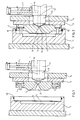
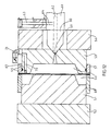
- a first mold half 1 of an injection mold is arranged on a first clamping plate 2 and a second mold half 3 on a second clamping plate 4.
- the mold half 1 has a cavity 5, over which a film 6 to be deformed (FIG. 1) is placed.
- the mold half 3 is provided with hold-down 7. It also has an injection channel 8 which is connected to an indicated injection molding unit 11 via a nozzle opening 9 of an injection nozzle 10.
- This injection nozzle 10 has a channel 12, into which a supply channel 14 for a gaseous pressure medium opens, which can be shut off by means of a sealing piston 13.
- the channel 12 is connected to the melt chamber (not shown) of an injection molding unit 11.
- the mold halves 1 and 3 are moved together, the mold half 3 holds the film 6 in position with its hold-down devices 7 and the injection nozzle 10 is attached. In this position, the seal 18 seals the cavity 5.
- Compressed air of 50 bar is then introduced via the feed channel 14 and the nozzle opening 9, as a result of which the film 6 suddenly deforms and assumes the desired geometry of the cavity 5, as shown in FIG. 3.
- the air behind the film 6 is pressed out by suitable ventilation channels (not shown) or by sintered inserts.
- thermoplastic mass 15 thermoplastic polyurethane
- injection molding unit 11 a flowable thermoplastic mass 15 (thermoplastic polyurethane) is injected by means of the injection molding unit 11, the pressure which further builds up being relieved by the pressure medium escaping through the mold gap 16 between the two mold halves 1 and 3.
- FIG. 4 shows the injection mold with the cavity 5 filled.
- FIG. 5 shows the molding tool opened for removing the multi-layer molded body 17.
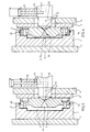
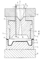
- a first mold half 21 of an injection mold is arranged on a first clamping plate 22 and a second mold half 23 on a second clamping plate 24.
- the mold half 21 has one Cavity 25, over which a film 26 to be deformed is placed.
- the upper mold half 23 is provided with an annular hold-down device 27, in which a displaceable core 38 is arranged.
- This core 38 has an injection channel 28, which is connected to an indicated injection molding unit 31 via a nozzle opening 29 of an injection nozzle 30.
- This injection nozzle 30 has a channel 32, which is connected to the melt chamber (not shown) of the injection molding unit 31.
- a separate feed channel 34 for compressed air can be shut off by means of a sealing piston 33.
- Fig. 7 the mold halves 21 and 23 are moved together, the hold-down 27 holds the film 26 in position and the injection nozzle 30 is attached.
- Compressed air of 300 bar is then introduced via the feed channel 34, as a result of which the film 26 suddenly deforms and assumes the desired geometry of the cavity 25, as shown in FIG. 8.
- the air behind the film is pressed out through suitable ventilation channels or sintering inserts, not shown.
- thermosetting compound 35 is injected into the cavity 25 by means of the injection molding unit 31.
- the pressure in the cavity 25 is controlled, which is determined by the mold clamping force and the injection pressure.
- Nitrogen is used as the pressure medium, which is gradually completely displaced by the thermosetting composition 35.
- the injection mold can be seen from FIG. 9 with the cavity filled.
- FIG. 10 shows the molding tool opened for removing the finished multilayer molded body 37.
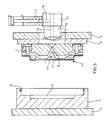
- a mold half 51 of an injection mold is arranged on a platen 52 and a second mold half 53 on a second platen 54.
- the mold half 51 forms, together with a clamping frame part 68, a cavity 55 (FIG. 12).
- a film 56 is clamped between this clamping frame part 68 and a clamping frame part 57.
- the mold half 53 has a gating channel 58 which, via a nozzle opening 59, connects an injection nozzle 60 to an indicated injection molding unit 61.
- This injection nozzle 60 has a channel 62, into which opens via a feed channel 64 for a gaseous pressure medium that can be shut off by means of a sealing piston 63.
- the channel 62 is connected to the melt chamber (not shown) of an indicated injection molding unit 61.
- Fig. 12 the injection mold is shown closed.
- the film 55 is held in position by the tenter frame part 57.
- a flowable thermoplastic composition 65 is injected through the channel 62 into the cavity 55 by means of the injection molding unit 61, the pressure being kept constant by a sintering insert 69, a channel 70 and a pressure-maintaining valve 71.
- the injection mold is shown with the cavity 55 filled in FIG. 14.
- FIG. 15 shows the injection mold that is open for removing the multilayer molded body 67. After the clamping frame parts 57 and 68 have been taken apart, the multilayer molded body 67 formed can be removed.
Landscapes
- Engineering & Computer Science (AREA)
- Manufacturing & Machinery (AREA)
- Mechanical Engineering (AREA)
- Injection Moulding Of Plastics Or The Like (AREA)
Abstract
Description
- Die Erfindung betrifft ein Verfahren zum Herstellen von Mehrschichtformkörpern aus einer verformbaren Folie und einem thermoplastischen oder duroplastischen Harz, wobei die Folie in der Kavität eines Formwerkzeuges mittels eines fluiden Mediums unter einem Druck von mindestens 20 bar verformt wird und mit dem Harz hinterspritzt wird.
- Dieses Verfahren ist aus DE 38 40 542 C1 bekannt. Hier handelt es sich insbesondere um eine bedruckte Kunststoffolie, z.B. Polycarbonatfolie, wobei der Aufdruck vor der Verformung aufgebracht wird und nach der Verformung exakt plaziert sein soll. Das Hinterspritzen der verformten Folie dient deren höheren Stabilität. Dabei entsteht ein Mehrschichtformkörper. Das Verformen der Folie erfolgt in einem ersten Formwerkzeug, welches eine der gewünschten Geometrie der verformten Folie entsprechende Kavität aufweist. Das Hinterspritzen findet in einem zweiten, separaten, Spritzgießformwerkzeug statt.
- Da zwei Formwerkzeuge benötigt werden, sind manuelle oder automatische Zwischenschritte zum Entnehmen der verformten Folie aus dem ersten Formwerkzeug und zum Transportieren und Einlegen in das zweite Formwerkzeug notwendig. Weil die verformte Folie relativ instabil ist, ist das Plazieren im zweiten Formwerkzeug sehr zeitraubend und durch Verrutschen der Folie entsteht immer wieder Ausschuß.
- Es besteht die Aufgabe, das eingangs beschriebene Verfahren zum Herstellen von Mehrschichtformkörpern zu vereinfachen und die Ausschußquote zu senken.
- Dies wird dadurch erreicht, daß die Verformung der Folie in der Kavität eines Spritzgießformwerkzeuges durchgeführt wird und daß die Folie direkt anschließend in dieser Kavität hinterspritzt wird, wobei während des Hinterspritzens ein die verformte Folie in Position haltender Druck aufrechterhalten wird.
- Durch die Verwendung desselben Spritzgießformwerkzeuges sowohl für die Verformung der Folie als auch für deren Hinterspritzen mit einem Harz verringert sich der maschinelle und manuelle Aufwand erheblich und die Ausschußquote verringert sich. Als Druckmedien eignen sich flüssige oder gasförmige, wobei den gasförmigen, wie Druckluft oder Inertgase, wie Stickstoff, Helium, Argon, der Vorzug zu geben ist. Als Folienmaterial eignet sich besonders gut Polycarbonat. Weitere geeignete Kunststoffolien bzw. Folienwerkstoffe sind in DE 38 40 542 C1 beschrieben. Aber auch hochstreckfähige metallische Folien sind geeignet.
- Für das neue Verfahren ist es ohne Belang, ob die Folien bedruckt oder unbedruckt sind. Als Thermoplaste und Duroplaste für das Hinterspritzen kommen alle solchen in Frage, welche spritzgießfähig sind und welche den vom Endprodukt geforderten Eigenschaften entsprechen. Die Verformung der Folie durch das Druckmedium findet sehr schnell statt, so daß man von einer schlagartigen Verformung sprechen kann, insbesondere, wenn man höhere Drücke anwendet. Der beim Spritzgießen in der Kavität herrschende Druck kann niedriger oder höher sein als der für die Verformung der Folie benötigte Druck, sofern er nur ausreichend ist, die verformte Folie bis zum Spritzgießen und während des Spritzgießens in Position zu halten. Da die verformte Folie durch diesen Druck an der Wandung der Kavität haften bleibt, kann beim Hinterspritzen auch keine Spritzgießmasse zwischen die Folie und die Wandung der Kavität eindringen und durch die exakte Plazierung der Folie kann auch kein Ausschuß entstehen, wie er bei schlecht oder falsch plazierter Folie auftritt.
- Vorzugsweise wird während des Hinterspritzens der zur Verformung der Folie aufgebrachte Druck aufrechterhalten, wobei der durch den Hinterspritzvorgang ansteigende Druck kontrolliert abgebaut wird.
- Dieser kontrollierte Abbau erfolgt beispielsweise durch eine auf das Spritzgießformwerkzeug definiert aufgebrachte Schließkraft, so daß überschüssiges Druckmedium durch den Spalt zwischen den Formwerkzeughälften in dem Maße entweichen kann, wie es durch die eingespritzte Kunststoffmasse verdrängt wird. Alternativ und noch besser steuerbar ist eine Druckentlastung durch ein Überdruckventil in einer mit der Kavität verbundenen Entlüftungsleitung.
- Gemäß einer besonderen Durchführungsform des neuen Verfahrens wird das Druckmedium durch die Einspritzdüse einer dem Spritzgießformwerkzeug zugeordneten Spritzgießeinheit eingeführt.
- Dies hat den Vorteil, daß in der Kavität keine zusätzliche Öffnung vorhanden sein muß. Das fluide Druckmedium strömt dabei beispielsweise über einen Stichkanal, welcher mittels eines Schiebers oder Kolbens absperrbar ist, in den Düsenkanal.
- Alternativ wird das fluide Medium durch einen besonderen, gegen Eindringen von Harz abdichtbaren Zuführkanal eingebracht.
- Hier ist zwar der Nachteil einer zweiten Öffnung in der Kavität in Kauf zu nehmen, aber andererseits kann man die Mündung dieses Kanals in der Kavität an eine geeignete Stelle legen, so daß Einschlüsse von Druckmedium beim Hinterspritzen mit Sicherheit ausgeschlossen werden.
- Schließlich ist es auch möglich, das Druckmedium durch einen zwischen der Einspritzdüse und deren Ansatztrichter am Spritzgießformwerkzeug belassenen Ringspalt einzuführen und die Einspritzdüse erst nach dem Einbringen des Druckmediums abdichtend an diesen Ansatztrichter anzusetzen, um dann die Kunststoffmasse einzuspritzen.
- In der Zeichnung sind drei geeignete Spritgießformwerkzeuge den einzelnen Verfahrensschritten entsprechend im Schnitt dargestellt und nachstehend näher erläutert.
- Es zeigen:
- Fig. 1 bis 5
- den Verfahrensablauf in einem ersten Spritzgießformwerkzeug,
- Fig. 6 bis 10
- den Verfahrensablauf in einem zweiten Spritzgießformwerkzeug und
- Fig. 11 bis 15
- den Verfahrensablauf in einem dritten Spritzgießformwerkzeug.
- In Fig. 1 bis 5 sind eine erste Formhälfte 1 eines Spritzgießformwerkzeuges auf einer ersten Aufspannplatte 2 und eine zweite Formhälfte 3 auf einer zweiten Aufspannplatte 4 angeordnet. Die Formhälfte 1 weist eine Kavität 5 auf, über welche eine zu verformende Folie 6 (Fig. 1) gelegt ist. Die Formhälfte 3 ist mit Niederhaltern 7 versehen. Sie weist außerdem einen Einspritzkanal 8 auf, welcher über eine Düsenöffnung 9 einer Einspritzdüse 10 mit einer angedeuteten Spritzgießeinheit 11 in Verbindung steht. Diese Einspritzdüse 10 weist einen Kanal 12 auf, in welchen ein mittels eines Verschlußkolbens 13 absperrbarer Zuführkanal 14 für ein gasförmiges Druckmedium mündet. Der Kanal 12 ist mit dem nicht dargestellten Schmelzeraum einer Spritzgießeinheit 11 verbunden.
- In Fig. 2 sind die Formhälften 1 und 3 zusammengefahren, die Formhälfte 3 hält mit ihren Niederhaltern 7 die Folie 6 in Position und die Einspritzdüse 10 ist angesetzt. In dieser Stellung dichtet die Dichtung 18 die Kavität 5 ab.
- Sodann wird über den Zuführkanal 14 und die Düsenöffnung 9 Druckluft von 50 bar eingeleitet, wodurch sich die Folie 6 schlagartig verformt und die gewünschte Geometrie der Kavität 5 annimmt, wie in Fig. 3 dargestellt. Die Luft hinter der Folie 6 wird durch nicht dargestellte geeignete Entlüftungskanäle oder durch Sintereinsätze herausgepreßt.
- Direkt anschließend wird mittels der Spritzgießeinheit 11 eine fließfähige thermoplastische Masse 15 (thermoplastisches Polyurethan) eingespritzt, wobei der dabei weiter aufbauende Druck durch Entweichen des Druckmediums durch den Formspalt 16 zwischen den beiden Formhälften 1 und 3 abgebaut wird.
- In Figur 4 ist das Spritzgießformwerkzeug mit gefüllter Kavität 5 dargestellt.
- In Fig. 5 schließlich ist das zum Entnehmen des Mehrschichtformkörpers 17 geöffnete Formwerkzeug gezeigt.
- In Fig. 6 bis 11 sind eine erste Formhälfte 21 eines Spritzgießformwerkzeuges auf einer ersten Aufspannplatte 22 und eine zweite Formhälfte 23 auf einer zweiten Aufspannplatte 24 angeordnet. Die Formhälfte 21 weist eine Kavität 25 auf, über welche eine zu verformende Folie 26 gelegt ist. Die obere Formhälfte 23 ist mit einem ringförmigen Niederhalter 27 versehen, in welchem ein verschiebbarer Kern 38 angeordnet ist. Dieser Kern 38 weist einen Einspritzkanal 28 auf, welcher über eine Düsenöffnung 29 einer Einspritzdüse 30 mit einer angedeuteten Spritzgießeinheit 31 in Verbindung steht. Diese Einspritzdüse 30 weist einen Kanal 32 auf, welcher mit dem nicht dargestellten Schmelzeraum der Spritzgießeinheit 31 verbunden ist. Ein gesonderter Zuführkanal 34 für Druckluft ist mittels eines Verschlußkolbens 33 absperrbar.
- In Fig. 7 sind die Formhälften 21 und 23 zusammengefahren, der Niederhalter 27 hält die Folie 26 in Position und die Einspritzdüse 30 ist angesetzt.
- Dann wird über den Zuführkanal 34 Druckluft von 300 bar eingeleitet, wodurch sich die Folie 26 schlagartig verformt und die gewünschte Geometrie der Kavität 25 annimmt, wie in Fig. 8 dargestellt. Die Luft hinter der Folie wird durch nicht dargestellte geeignete Entlüftungskanäle oder Sintereinsätze herausgepreßt.
- Direkt anschließend wird der Zuführkanal 34 mittels des Verschlußkolbens 33 verschlossen und mittels der Spritzgießeinheit 31 wird eine duroplastische Masse 35 in die Kavität 25 eingespritzt. Dabei wird der Druck in der Kavität 25 kontrolliert, der durch die Formzuhaltekraft und den Einspritzdruck bestimmt wird.
- Als Druckmedium wird hier Stickstoff verwendet, welcher nach und nach von der duroplastischen Masse 35 völlig verdrängt wird.
- Das Spritzgießformwerkzeug ist mit gefüllter Kavität aus Fig. 9 ersichtlich.
- In Fig. 10 schließlich ist das zum Entnehmen des fertigen Mehrschichtformkörpers 37 geöffnete Formwerkzeug dargestellt.
- In Fig. 11 bis 15 sind eine Formhälfte 51 eines Spritzgießformwerkzeuges auf einer Aufspannplatte 52 und eine zweite Formhälfte 53 auf einer zweiten Aufspannplatte 54 angeordnet. Die Formhälfte 51 bildet zusammen mit einem Spannrahmenteil 68 eine Kavität 55 (Fig. 12). Zwischen diesem Spannrahmenteil 68 und einem Spannrahmenteil 57 ist eine Folie 56 eingespannt. Die Formhälfte 53 weist einen Anspritzkanal 58 auf, welcher über eine Düsenöffnung 59 eine Einspritzdüse 60 mit einer angedeuteten Spritzgießeinheit 61 in Verbindung steht. Diese Einspritzdüse 60 weist einen Kanal 62 auf, in welchen über ein mittels eines Verschlußkolbens 63 absperrbarer Zuführkanal 64 für ein gasförmiges Druckmedium mündet.
- Der Kanal 62 ist mit dem nicht dargestellten Schmelzeraum einer angedeuteten Spritzgießeinheit 61 verbunden.
- In Fig. 12 ist das Spritzgießformwerkzeug geschlossen dargestellt. Die Folie 55 wird durch den Spannrahmenteil 57 in Position gehalten.
- Sodann wird über den Zuführkanal 64 und die Düsenöffnung 59 Stickstoff von 200 bar eingeleitet, wodurch sich die Folie 56 schlagartig verformt und die gewünschte Geometrie der Kavität 55 annimmt, wie in Fig. 13 dargestellt. Die Luft hinter der Folie 56 entweicht durch den Spalt zwischen der Formhälfte 51 und dem Spannrahmenteil 68.
- Direkt anschließend wird mittels der Spritzgießeinheit 61 eine fließfähige thermoplastische Masse 65 durch den Kanal 62 in die Kavität 55 eingespritzt, wobei der Druck durch einen Sintereinsatz 69, einen Kanal 70 und ein Druckhalteventil 71 konstant gehalten wird. Das Spritzgießformwerkzeug ist mit gefüllter Kavität 55 in Fig. 14 dargestellt.
- In Fig. 15 schließlich ist das zum Entnehmen des Mehrschichtformkörpers 67 geöffnete Spritzgießformwerkzeug gezeigt. Nach Auseinandernehmen der Spannrahmenteile 57 und 68 läßt sich der gebildete Mehrschichtformkörper 67 entnehmen.
Claims (4)
- Verfahren zum Herstellen von Mehrschichtformkörpern (17, 37, 67) aus einer verformbaren Folie (6, 26, 56) und einem thermoplastischen oder duroplastischen Harz (15, 35, 65), wobei die Folie (6, 26, 56) in der Kavität (5, 25, 55) eines Formwerkzeuges mittels eines fluiden Mediums unter einem Druck von mindestens 20 bar verformt und anschließend mit dem Harz (15, 35, 65) hinterspritzt wird, dadurch gekennzeichnet, daß die Verformung der Folie (6, 26, 56) in der Kavität (5, 25, 55) eines Spritzgießformwerkzeuges durchgeführt wird und daß die Folie (6, 26, 56) direkt anschließend in dieser Kavität (5, 25, 55) hinterspritzt wird, wobei während des Hinterspritzens ein die verformte Folie (6, 26, 56) in Position haltender Druck aufrechterhalten wird.
- Verfahren nach Anspruch 1, dadurch gekennzeichnet, daß während des Hinterspritzens der zur Verformung der Folie (6, 26, 56) aufgebrachte Druck aufrechterhalten wird, wobei der beim Hinterspritzen ansteigende Druck kontrolliert abgebaut wird.
- Verfahren nach Anspruch 1 oder 2, dadurch gekennzeichnet, daß das fluide Medium durch die Einspritzdüse (10, 60) einer dem Spritzgießformwerkzeug zugeordneten Spritzgießeinheit (11, 61) zugeführt wird.
- Verfahren nach Anspruch 1 oder 2, dadurch gekennzeichnet, daß das fluide Medium durch einen besonderen, gegen Eindringen von Harz abdichtbaren Zuführkanal (34) eingebracht wird.
Applications Claiming Priority (2)
| Application Number | Priority Date | Filing Date | Title |
|---|---|---|---|
| DE4004029 | 1990-02-10 | ||
| DE4004029 | 1990-02-10 |
Publications (3)
| Publication Number | Publication Date |
|---|---|
| EP0442128A2 true EP0442128A2 (de) | 1991-08-21 |
| EP0442128A3 EP0442128A3 (en) | 1992-01-15 |
| EP0442128B1 EP0442128B1 (de) | 1997-07-09 |
Family
ID=6399825
Family Applications (1)
| Application Number | Title | Priority Date | Filing Date |
|---|---|---|---|
| EP90125212A Expired - Lifetime EP0442128B1 (de) | 1990-02-10 | 1990-12-21 | Verfahren zum Herstellen von Mehrschichtformkörpern |
Country Status (5)
| Country | Link |
|---|---|
| US (1) | US5236657A (de) |
| EP (1) | EP0442128B1 (de) |
| JP (1) | JP3083333B2 (de) |
| DE (1) | DE59010734D1 (de) |
| ES (1) | ES2103265T3 (de) |
Cited By (5)
| Publication number | Priority date | Publication date | Assignee | Title |
|---|---|---|---|---|
| EP0584042A1 (de) * | 1992-08-04 | 1994-02-23 | Emery I. Valyi | Verfahren und Vorrichtung zur Herstellung eines farbbeschichteten Gegenstandes |
| EP0890424A1 (de) * | 1997-07-11 | 1999-01-13 | IBS Brocke GmbH & Co. KG | Verfahren zur Herstellung von hinterspritzten Kunststoffformteilen |
| NL1012957C2 (nl) * | 1998-09-01 | 2000-03-02 | Corell Resin Technology Bv | Werkwijze voor het vervaardigen van een kunststof voorwerp, alsmede spuitgietmatrijs. |
| WO2000012282A1 (en) * | 1998-09-01 | 2000-03-09 | Corell Resin Technology B.V. | Method for manufacturing a plastic object, and an injection mould |
| WO2000073038A1 (de) * | 1999-06-01 | 2000-12-07 | Packtech Limited | Verfahren und vorrichtung zur herstellung von zumindest zweischichtigen formkörpern aus kunststoffen |
Families Citing this family (7)
| Publication number | Priority date | Publication date | Assignee | Title |
|---|---|---|---|---|
| DE19500790A1 (de) * | 1995-01-13 | 1996-07-18 | Bayer Ag | Verfahren und Vorrichtung zur Herstellung von Kunststoff/Metallverbundkörpern |
| IL117538A (en) * | 1996-03-18 | 2001-08-26 | Lotemplast Plastic Product Com | In-mold decorated plastic articles |
| US6113827A (en) | 1996-11-05 | 2000-09-05 | Styczynski; Robert J. | Method for molding and curing silicone |
| GB2408960B (en) * | 2003-12-12 | 2008-01-30 | Nokia Corp | In-mould labelling |
| CN101274464A (zh) * | 2007-03-29 | 2008-10-01 | 鸿富锦精密工业(深圳)有限公司 | 模具 |
| CN101279487B (zh) * | 2007-04-05 | 2010-11-10 | 康准电子科技(昆山)有限公司 | 模具 |
| JP6766734B2 (ja) * | 2017-04-03 | 2020-10-14 | トヨタ自動車株式会社 | ヒートシンクの製造方法 |
Family Cites Families (9)
| Publication number | Priority date | Publication date | Assignee | Title |
|---|---|---|---|---|
| DE1729368A1 (de) * | 1967-10-13 | 1971-06-09 | Per Thorkildsen | Verfahren und Vorrichtung zur Herstellung von dekorierten,spritzgegossenen Plastgegenstaenden |
| US4418033A (en) * | 1979-06-20 | 1983-11-29 | Yoshiharu Hatakeyama | Method of manufacturing a decorated forming article |
| US4545752A (en) * | 1982-08-17 | 1985-10-08 | Dai Nippon Insatsu Kabushiki Kaisha | Device for injection molding articles while simultaneously forming patterns thereon |
| JPS6089318A (ja) * | 1983-10-24 | 1985-05-20 | Toshiba Mach Co Ltd | 射出成形方法 |
| US4781554A (en) * | 1987-07-09 | 1988-11-01 | Michael Ladney | Apparatus for the injection molding of thermoplastics |
| US4942006A (en) * | 1988-12-01 | 1990-07-17 | Michael Ladney | Method of and apparatus for injection molding with pressurized-fluid assist |
| JPH02199426A (ja) * | 1989-01-30 | 1990-08-07 | Seiko Epson Corp | 液晶表示装置 |
| US4917594A (en) * | 1989-02-28 | 1990-04-17 | Mold-Masters Limited | Injection molding system with gas flow through valve gate |
| US5000903A (en) * | 1989-04-06 | 1991-03-19 | Libbey-Owens-Ford Co. | Method of molding plastic products having chemically bonded protective coatings |
-
1990
- 1990-12-21 ES ES90125212T patent/ES2103265T3/es not_active Expired - Lifetime
- 1990-12-21 EP EP90125212A patent/EP0442128B1/de not_active Expired - Lifetime
- 1990-12-21 DE DE59010734T patent/DE59010734D1/de not_active Expired - Fee Related
-
1991
- 1991-01-25 US US07/645,815 patent/US5236657A/en not_active Expired - Lifetime
- 1991-02-07 JP JP03036494A patent/JP3083333B2/ja not_active Expired - Lifetime
Cited By (6)
| Publication number | Priority date | Publication date | Assignee | Title |
|---|---|---|---|---|
| EP0584042A1 (de) * | 1992-08-04 | 1994-02-23 | Emery I. Valyi | Verfahren und Vorrichtung zur Herstellung eines farbbeschichteten Gegenstandes |
| EP0890424A1 (de) * | 1997-07-11 | 1999-01-13 | IBS Brocke GmbH & Co. KG | Verfahren zur Herstellung von hinterspritzten Kunststoffformteilen |
| NL1012957C2 (nl) * | 1998-09-01 | 2000-03-02 | Corell Resin Technology Bv | Werkwijze voor het vervaardigen van een kunststof voorwerp, alsmede spuitgietmatrijs. |
| WO2000012282A1 (en) * | 1998-09-01 | 2000-03-09 | Corell Resin Technology B.V. | Method for manufacturing a plastic object, and an injection mould |
| WO2000073038A1 (de) * | 1999-06-01 | 2000-12-07 | Packtech Limited | Verfahren und vorrichtung zur herstellung von zumindest zweischichtigen formkörpern aus kunststoffen |
| CH693562A5 (de) * | 1999-06-01 | 2003-10-15 | Packtech Ltd | Verfahren und Vorrichtung zur Herstellung eines zumindest zweischichtigen Formkörpers aus Kunststoff und nach dem Verfahren hergestellten Formkörper. |
Also Published As
| Publication number | Publication date |
|---|---|
| ES2103265T3 (es) | 1997-09-16 |
| EP0442128B1 (de) | 1997-07-09 |
| DE59010734D1 (de) | 1997-08-14 |
| US5236657A (en) | 1993-08-17 |
| JPH04212823A (ja) | 1992-08-04 |
| JP3083333B2 (ja) | 2000-09-04 |
| EP0442128A3 (en) | 1992-01-15 |
Similar Documents
| Publication | Publication Date | Title |
|---|---|---|
| DE3853192T2 (de) | Verfahren zum Spritzgiessen, Vorrichtung dafür und danach hergestellte Formteile. | |
| DE3850543T3 (de) | Verfahren zum Spritzgiessen | |
| DE69115265T2 (de) | Verfahren und vorrichtung zum spritzgiessen von kunststoffgegenständen mit hilfe von gas. | |
| EP0393315B1 (de) | Verfahren zum Spritzgiessen fluidgefüllter Kunststoffkörper und Vorrichtung zur Durchführung des Verfahrens | |
| EP2089207B1 (de) | Verfahren und Vorrichtung zur Herstellung eines Verbundbauteils, insbesondere umfassend ein Spritzgussteil mit einer Polyurethan-Beschichtung | |
| DE69202709T2 (de) | Verfahren zur Herstellung eines geformten Hohlkörpers. | |
| DE102012023608B4 (de) | Verfahren und Vorrichtung zum Herstellen eines Formteils | |
| DE69226270T2 (de) | Verfahren zum spritzgiessen von holen plastikgegenständen | |
| EP0671249B1 (de) | Verfahren und Vorrichtung zur Herstellung optischen Linsen | |
| DE69224900T2 (de) | Verfahren und system zum spritzgiessen unter verwendung einer druckgasquelle in einem raum in der form | |
| EP0442128B1 (de) | Verfahren zum Herstellen von Mehrschichtformkörpern | |
| DE3910025C2 (de) | ||
| DE69405373T2 (de) | Verfahren und Vorrichtung zum Giessen von Formkörpern aus Kunststoff unterschiedlicher Dichte | |
| DE19543944A1 (de) | Verfahren und Vorrichtung zum Herstellen von Kunststoffgegenständen | |
| DE202019100162U1 (de) | Spritzgusswerkzeug für die Herstellung von Behältern aus Kunststoff | |
| DE102007037748B3 (de) | Formwerkzeug und Verfahren zum Tiefziehen von Behältern aus einer erwärmten Folienbahn aus thermoplastischem Kunststoff | |
| DE10355300A1 (de) | Verfahren zum Spritzgießen von Kunststoffmaterialien unter Verwendung von Gashaltedruck in der Form | |
| EP0754533B1 (de) | Verfahren zum Verarbeiten von Kunststoff | |
| DE60213641T2 (de) | Form und verfahren zum transferspritzen von kunstharz ("r.t.m.") | |
| DE2348006C2 (de) | Verfahren und Vorrichtung zur Herstellung von Formteilen aus treibmittelhaltigem, thermoplastischem Kunststoff | |
| DE3880993T3 (de) | Verfahren zum Spritzgiessen und dafür angewandte Düse. | |
| DE19832807A1 (de) | Verfahren und Vorrichtung zur Herstellung von Spritzgießteilen | |
| EP0673746A1 (de) | Verfahren und Vorrichtung zur Herstellung von Formteilen aus Mehrkomponenetenkunststoffen | |
| DE10001229C1 (de) | Spritzgießwerkzeug zum Fertigen eines Kunststoffteils | |
| DE2203814B2 (de) | Verfahren und Vorrichtung zur Herstellung von Spritzgußgegenständen aus zwei unterschiedlichen Kunststoffmaterialien |
Legal Events
| Date | Code | Title | Description |
|---|---|---|---|
| PUAI | Public reference made under article 153(3) epc to a published international application that has entered the european phase |
Free format text: ORIGINAL CODE: 0009012 |
|
| 17P | Request for examination filed |
Effective date: 19901221 |
|
| AK | Designated contracting states |
Kind code of ref document: A2 Designated state(s): DE ES FR GB IT |
|
| PUAL | Search report despatched |
Free format text: ORIGINAL CODE: 0009013 |
|
| AK | Designated contracting states |
Kind code of ref document: A3 Designated state(s): DE ES FR GB IT |
|
| 17Q | First examination report despatched |
Effective date: 19930723 |
|
| GRAG | Despatch of communication of intention to grant |
Free format text: ORIGINAL CODE: EPIDOS AGRA |
|
| GRAH | Despatch of communication of intention to grant a patent |
Free format text: ORIGINAL CODE: EPIDOS IGRA |
|
| GRAH | Despatch of communication of intention to grant a patent |
Free format text: ORIGINAL CODE: EPIDOS IGRA |
|
| GRAA | (expected) grant |
Free format text: ORIGINAL CODE: 0009210 |
|
| AK | Designated contracting states |
Kind code of ref document: B1 Designated state(s): DE ES FR GB IT |
|
| GBT | Gb: translation of ep patent filed (gb section 77(6)(a)/1977) |
Effective date: 19970709 |
|
| REF | Corresponds to: |
Ref document number: 59010734 Country of ref document: DE Date of ref document: 19970814 |
|
| REG | Reference to a national code |
Ref country code: ES Ref legal event code: FG2A Ref document number: 2103265 Country of ref document: ES Kind code of ref document: T3 |
|
| ITF | It: translation for a ep patent filed | ||
| ET | Fr: translation filed | ||
| PLBE | No opposition filed within time limit |
Free format text: ORIGINAL CODE: 0009261 |
|
| STAA | Information on the status of an ep patent application or granted ep patent |
Free format text: STATUS: NO OPPOSITION FILED WITHIN TIME LIMIT |
|
| 26N | No opposition filed | ||
| REG | Reference to a national code |
Ref country code: GB Ref legal event code: IF02 |
|
| PGFP | Annual fee paid to national office [announced via postgrant information from national office to epo] |
Ref country code: FR Payment date: 20081212 Year of fee payment: 19 Ref country code: ES Payment date: 20090120 Year of fee payment: 19 |
|
| PGFP | Annual fee paid to national office [announced via postgrant information from national office to epo] |
Ref country code: DE Payment date: 20081219 Year of fee payment: 19 |
|
| PGFP | Annual fee paid to national office [announced via postgrant information from national office to epo] |
Ref country code: GB Payment date: 20081217 Year of fee payment: 19 |
|
| PGFP | Annual fee paid to national office [announced via postgrant information from national office to epo] |
Ref country code: IT Payment date: 20081229 Year of fee payment: 19 |
|
| GBPC | Gb: european patent ceased through non-payment of renewal fee |
Effective date: 20091221 |
|
| REG | Reference to a national code |
Ref country code: FR Ref legal event code: ST Effective date: 20100831 |
|
| PG25 | Lapsed in a contracting state [announced via postgrant information from national office to epo] |
Ref country code: FR Free format text: LAPSE BECAUSE OF NON-PAYMENT OF DUE FEES Effective date: 20091231 |
|
| PG25 | Lapsed in a contracting state [announced via postgrant information from national office to epo] |
Ref country code: DE Free format text: LAPSE BECAUSE OF NON-PAYMENT OF DUE FEES Effective date: 20100701 |
|
| PG25 | Lapsed in a contracting state [announced via postgrant information from national office to epo] |
Ref country code: GB Free format text: LAPSE BECAUSE OF NON-PAYMENT OF DUE FEES Effective date: 20091221 |
|
| PG25 | Lapsed in a contracting state [announced via postgrant information from national office to epo] |
Ref country code: IT Free format text: LAPSE BECAUSE OF NON-PAYMENT OF DUE FEES Effective date: 20091221 |
|
| REG | Reference to a national code |
Ref country code: ES Ref legal event code: FD2A Effective date: 20110408 |
|
| PG25 | Lapsed in a contracting state [announced via postgrant information from national office to epo] |
Ref country code: ES Free format text: LAPSE BECAUSE OF NON-PAYMENT OF DUE FEES Effective date: 20110328 |
|
| PG25 | Lapsed in a contracting state [announced via postgrant information from national office to epo] |
Ref country code: ES Free format text: LAPSE BECAUSE OF NON-PAYMENT OF DUE FEES Effective date: 20091222 |