EP0442161B1 - Dispositif pour la projection d'image de télévision - Google Patents
Dispositif pour la projection d'image de télévision Download PDFInfo
- Publication number
- EP0442161B1 EP0442161B1 EP90203387A EP90203387A EP0442161B1 EP 0442161 B1 EP0442161 B1 EP 0442161B1 EP 90203387 A EP90203387 A EP 90203387A EP 90203387 A EP90203387 A EP 90203387A EP 0442161 B1 EP0442161 B1 EP 0442161B1
- Authority
- EP
- European Patent Office
- Prior art keywords
- arm
- lcd
- adjustment
- shaped
- light
- Prior art date
- Legal status (The legal status is an assumption and is not a legal conclusion. Google has not performed a legal analysis and makes no representation as to the accuracy of the status listed.)
- Expired - Lifetime
Links
- 230000008878 coupling Effects 0.000 claims description 13
- 238000010168 coupling process Methods 0.000 claims description 13
- 238000005859 coupling reaction Methods 0.000 claims description 13
- 230000000994 depressogenic effect Effects 0.000 claims description 12
- 238000006073 displacement reaction Methods 0.000 description 12
- 238000010276 construction Methods 0.000 description 5
- 239000000463 material Substances 0.000 description 2
- 239000003086 colorant Substances 0.000 description 1
- 238000001816 cooling Methods 0.000 description 1
- 230000007423 decrease Effects 0.000 description 1
- 239000000428 dust Substances 0.000 description 1
- 238000003780 insertion Methods 0.000 description 1
- 230000037431 insertion Effects 0.000 description 1
- 239000004973 liquid crystal related substance Substances 0.000 description 1
- 230000006798 recombination Effects 0.000 description 1
- 238000005215 recombination Methods 0.000 description 1
- 230000000630 rising effect Effects 0.000 description 1
Images

Classifications
-
- H—ELECTRICITY
- H04—ELECTRIC COMMUNICATION TECHNIQUE
- H04N—PICTORIAL COMMUNICATION, e.g. TELEVISION
- H04N5/00—Details of television systems
- H04N5/74—Projection arrangements for image reproduction, e.g. using eidophor
-
- H—ELECTRICITY
- H04—ELECTRIC COMMUNICATION TECHNIQUE
- H04N—PICTORIAL COMMUNICATION, e.g. TELEVISION
- H04N9/00—Details of colour television systems
- H04N9/12—Picture reproducers
- H04N9/31—Projection devices for colour picture display, e.g. using electronic spatial light modulators [ESLM]
- H04N9/3141—Constructional details thereof
- H04N9/317—Convergence or focusing systems
-
- Y—GENERAL TAGGING OF NEW TECHNOLOGICAL DEVELOPMENTS; GENERAL TAGGING OF CROSS-SECTIONAL TECHNOLOGIES SPANNING OVER SEVERAL SECTIONS OF THE IPC; TECHNICAL SUBJECTS COVERED BY FORMER USPC CROSS-REFERENCE ART COLLECTIONS [XRACs] AND DIGESTS
- Y10—TECHNICAL SUBJECTS COVERED BY FORMER USPC
- Y10S—TECHNICAL SUBJECTS COVERED BY FORMER USPC CROSS-REFERENCE ART COLLECTIONS [XRACs] AND DIGESTS
- Y10S353/00—Optics: image projectors
- Y10S353/05—Transparency holder accessories
Definitions
- the invention relates to a device for projecting television pictures, provided with a light source and dichroic mirrors which separate the light into three channels, the light being guided through an LCD in each channel, after which the light transmitted by the LCDs in the different channels is united by means of dichroic mirrors into a single channel to be supplied to a projection systems, each LCD being mounted to a common support member.
- Such a device is known from JP-A-63-116123.
- the light coming from a light source is separated into different colour components, such as red, green and blue, in three separate channels by means of dichroic mirrors.
- the light beams of different colours running in different channels and obtained in this way are then conducted through liquid crystal display units having two polaroids (referred to as LCDs hereinafter), which are known per se.
- LCDs are controlled by control means which are known per se, which are immaterial to the invention, and which will therefore not be described any further, in such a way that only desired portions of the light beams are transmitted in the various channels.
- the light beams thus transmitted by the LCDs are merged together again by means of dichroic mirrors into a single channel, and the combined light beam thus obtained is fed to a projection system for projecting the desired picture.
- the LCDs are mounted to a common support member or housing in which the light beams passing through the LCDs are to be combined by means of dichroic mirrors positioned in this support member or housing.
- this object can be achieved in that relative to the support member one of the LCDs occupies a fixed position while the two other LCDs are each connected to the support member by means of three adjustment members, the three adjustment members coupled to an LCD making contact with the relevant LCD in three coupling points which, seen in the movement of direction of the light through the relevant LCD, are staggered through subsequent angles of 90° relative to one another, so that each LCD is adjustable by means of each of the three adjustment members, one adjustment member for adjustment in a direction parallel to the direction of movement of the light through the relevant LCD, the other two adjustment members for adjustment in two mutually perpendicular directions which are perpendicular to the direction of movement of the light through the relevant LCD.
- a device for projecting television pictures in which light beams through three projection systems are projected in one point on a screen by means of three objectives.
- the device comprises adjustment means for mirrors, LCDs and lenses.
- the light beams are not merged together into a single channel. There is no further indication about the adjustment means.
- the LCD fixedly connected to the support member may be used as a reference member relative to which the other LCDs are brought into the correct position by means of the adjustment members coupled to the relevant LCDs. It has been found in practice that an accurate alignment of the LCDs can be achieved in this way, so that the separate pictures formed at the LCDs can be projected over one another in the correct manner.
- a further aspect of the invention relates to a device for fixing a disc-shaped member relative to a plate-shaped wall portion of a support member enclosing the disc-shaped member.
- the disc-shaped member or mirror can be inserted in the slot and a swivel movement of the finger-shaped member can be achieved through deformation of the two connection parts enclosing an angle with one another, in such a way that the free end of the said finger-shaped member presses the disc-shaped member against the bounding edge of the slot positioned opposite the free end of the finger-shaped member.
- a fixation of the disc-shaped member relative to the plate-shaped wall portion is thereby obtained in a simple manner owing to the permanent deformation of the connection parts enclosing an angle with one another without additional fastening means, which often form inconvenient obstacles, being necessary for this.
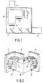
- Fig. 1 shows a rectangular housing 1 to whose side wall a lamp housing 2 is mounted, by means of which light can be radiated into the interior of the housing through an opening provided in the relevant wall.
- Three dichroic mirrors 3, 4 and 5 are positioned one after the other in the housing 1 in the light path of lamp housing 2. In known manner, these mirrors transmit only part of the incident light, while, seen in Fig. 1, part of the light incident on the mirrors in horizontal direction from the lamp housing 2 is deflected in vertical direction so that, for example, an upwardly directed channel of blue light is formed at mirror 3, an upwardly directed channel of green light is formed at mirror 4, and an upwardly directed channel of red light is formed at mirror 5.
- the light coming from the mirror 3 is deflected by a further mirror in the direction of a lens 7.
- the light deflected by the mirrors 4 and 5 is incident on lenses 8 and 9, respectively.
- the parallel centrelines of the lenses 8 and 9 extend in a direction perpendicular to the centreline of the lens 7.
- the lenses 7, 8 and 9 are positioned near wall portions of a housing 10 which is accommodated in the housing 1 and has a more or less L-shaped construction, which wall portions extend parallel to the said lenses.
- this housing 10 also called recombination housing, the light beams transmitted by the lenses 7, 8 and 9 in the housing are joined together again in a way yet to be described below and supplied as a single beam to a projection system 111 mounted to the housing, with which system a picture can be projected.
- LCDs 11-13 are mounted to the wall portions of the housing 10 situated opposite the lenses 7-9.
- the LCD 12 situated opposite the lens 8 occupies a fixed position relative to the housing 10 whereas the LCDs 11 and 13 are adjustable relative to the housing by means of adjustment members 14.
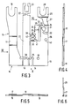
- Three adjustment members 14 are provided for the LCD 11 as well as for the LCD 13, which members are provided on three outer walls of the housing 10 which enclose subsequent angles of 90° with one another.
- the adjustment member comprises a first elongate leg 15 in whose free end a U-shaped recess 16 is provided.
- the width of the leg gradually decreases in the direction of a rectangular intermediate portion 17 of the leg, which portion is slightly depressed relative to the portions of the leg 15 situated on either side of it.
- connection piece 18 which at its side facing away from the leg 15 adjoins a substantially rectangular plate-shape portion 19.
- connection piece 18 is slightly depressed relative to the portions 15 and 19 which are integral with it and are situated on either side of it.
- connection piece By means of a connection ridge 20, whose width is considerably smaller than that of the connection piece 18, the connection piece is connected to the end of a leg 21 which extends substantially parallel to the leg 15 between the leg 15 and the plate-shape portion 19, and whose width is approximately equal to the width of the connection piece 18.
- connection ridge 22 whose dimensions correspond to those of the connection ridge 20
- the free end of the leg 21 is connected to a substantially U-shaped coupling piece 23, which is situated at approximately the same level as the free end of the leg 15 provided with the U-shaped recess 16.
- the leg 21 is in one plane with the portion 18 and will thus lie at a distance from the wall of the housing 10 in the assembled state.
- connection piece 19 a slot 24 extending parallel to the longitudinal direction of the connection piece is provided in the plate-shaped portion 19 near the connection piece 18, so that the plate-shaped portion is in fact only connected to the connection piece via a connection ridge 25, whose dimensions correspond to those of the connection ridges 20 and 22.
- the plate-shape portion has an extension 26 merging into an arm 27, which arm forms a connection between the end of the extension 26 and a plate portion 29 provided with a U-shaped recess 28.
- the arm 27 is again slightly depressed relative to the portions 29 and 26 situated on either side of it.
- a wedge-shaped opening 30 extending from a side of the extension 26 in the direction of the arm 21 is provided in the extension 26. Above this wedge-shaped opening 30, a circular hole 31 is formed in the extension 26, which hole merges into a slot 32 which extends from the boundary of the extension 26 facing the leg 21 to the hole 31.
- a connection piece 33 is formed in this way, connected at one end to the end of the extension 26 by means of a connection ridge 34 of small cross-section and at its other end to the end of a connection arm, which is built up of two portions 36 and 37 depressed relative to one another, by means of a connection ridge 35 of small cross-section.
- the portion 37 here lies in one plane with the depressed portions 18 and 21.
- connection pieces 38 and 39 merge into the end of the connection arm 36, 37 remote from the connection piece 33 via connection ridges 40 and 41, respectively, of comparatively small cross-section at the side of the connection arm facing away from the connection piece 33.
- connection piece 38 is connected to a side of the arm 21 near the centre of this arm by means of a further connection ridge 42 of small cross-section.
- connection piece 39 is connected to an edge of the plate-shaped portion 19 along an edge which extends perpendicularly to the arm 21.
- the plate-shaped portion 19 further accommodates two holes 43 and 44 through which screws, rivets, or the like can be inserted, by means of which the plate-shaped section 19 of the adjustment member 14 manufactured from a plate-shaped piece of material may be mounted to a wall of the housing 10 in the manner represented in Figs. 2 and 7.
- the depressed portion 17 is situated below a U-shaped bracket 45 which straddles this depressed portion 17 and is integral with the wall of the housing 10, against which bracket the depressed portion 17 is forcably pressed owing to the shape of the adjustment member 14.
- the depressed arm 27 is situated below a U-shaped bracket 46 which is integral with the wall of the housing 10, against which bracket the arm 27 is also forcibly pressed.
- one or several bores 47, 48, respectively, is/are provided in the wall of the housing 10 at the level of the U-shaped recesses 16 and 28 for a purpose yet to be described below.
- an adjustable LCD 11 is connected to a connection plate 49 which is surrounded by a dust rising 50.
- the LCD is further screened with transparent cover plates 51 mounted to a cooling frame 52.
- the connection plate 49 is coupled to the relevant three adjustment members 14 by means of bolts 53 which are inserted through the holes provided in the connection plate and screwed into the U-shaped coupling pieces 23, so that the connection plate, and thus the relevant LCD 11 is supported in three coupling points by adjustment members 14, the coupling points being positioned at subsequent angles of 90° relative to one another seen in the direction in which a light beam moves through the LCD.
- adjustment members 14 are provided on the outside of the housing 10, they are easily accessible.
- Such a displacement can be achieved by means of a peg whose diameter corresponds approximately to the width of the recess 16 or 28.
- a pin is provided at the bottom end of this peg in a position eccentric relative to the centreline of the peg and fitting in the bores 47 and 48.
- connection ridge 25 When the free end of the arm 15 is displaced in the direction of arrow A, the arm 15 will rotate relative to the remaining portion of the adjustment member 14 about a pivot point formed by the connection ridge 25.
- the rotation about the pivot point 25 displaces the connection piece 18 and the leg 21 connected to it at least substantially in longitudinal direction of this leg 21, which movement of the leg 21 is made possible in that a hinging movement can also occur in the connection ridges 40 and 42. It will be obvious that a displacement of the leg 21 in its longitudinal direction leads to a corresponding displacement of the coupling point by which the leg 21 is coupled to the connection plate 49 supporting the relevant LCD.
- this plate portion 29 is shifted in one of the two directions of arrow B, this plate portion together with the arm 27 will swivel about a pivot point formed by connection ridge 54 between the hole 31 and the inner end of the wedge-shaped opening 30.
- This movement of the arm 27 is transmitted by the connection piece 33 to the connection arm 36, 37, which will consequently swivel about the pivot point formed by the connection ridge 41.
- This swivel movement of the arm 36, 37 is transmitted again by the connection piece 38 to the leg 21, so that this leg 21 will swivel about the pivot point formed by the connection ridge 20.
- the use of the adjustment member renders it possible to achieve a displacement in two mutually perpendicular directions at the location of the coupling point between the adjustment member 14 and a connection plate 49 supporting a relevant LCD. Since each connection plate 49 supporting an LCD is connected to an adjustment member 14 in three points shifted 90° relative to one another, such a displacement can be achieved in two mutually perpendicular directions in these three points, so that it is possible to set the relevant LCD in any desired position. Thus it is possible to adjust the two adjustable LCDs in such a way that the pictures formed in these LCDs will coincide correctly with the picture formed by the LCD with fixed position, which serves as a reference.
- the design of the adjustment member 14 achieves that the displacement of the free end of the leg 15 causes a considerably smaller displacement of the leg 21 in its longitudinal direction; in the embodiment shown the ratio of these displacements is approximately 1 : 10.
- the displacement of the plate-shaped portion 29 in the direction of arrow B in the chosen embodiment of the adjustment member 14 also results in a considerably smaller displacement of the coupling piece 23; in the embodiment shown the ratio of these displacements is approximately 1 : 10.
- Fig. 8 shows diagrammatically the way in which an edge of a disc-shaped member, such as a mirror 55, may be fixed in a plate-shaped wall 56 of a housing.
- the boundary of the mirror 55 facing away from the wall 56 may, for example, be inserted in brackets or the like which are fastened to a side wall of the relevant housing situated opposite the wall 56.
- the mirror 55 is inserted in a slot 57 provided in the wall 56.
- a recess 58 provided in the wall 56 merges into this slot.
- a finger-shaped member 59 which is integral with the wall 56 and of which only one end is connected to the remaining portion of the plate-shaped member 56 by means of a connection ridge 60.
- the finger-shaped member 59 is further connected to the plate-shaped portion by means of two connection parts 61 and 62 which together enclose an angle and which are also integral with the finger-shaped member 59 and the wall 56.
- the finger-shaped member is provided with a nose 63 extending towards the mirror 55 at its free end facing away from the connection ridge 60. This nose 63 is situated opposite a projection 64 of the boundary of the slot 57, which lies at the side of the mirror 55 facing away from the nose 63.
- That portion of the finger-shaped member 59 which is situated between the connection parts 61 and 62 enclosing an angle with one another on the one hand and the projecting nose 63 on the other hand is of a narrower design over part 65 of its length than the remaining part of the finger-shaped member 59.
- the finger-shaped member 59 with its associated parts will initially be stamped out from the material of the wall 56 in the shape represented in Fig. 8. After insertion of the mirror 55, the two connection pieces enclosing an angle can be deformed with a suitable tool in such a way that the angle enclosed by these parts 61 and 62 will become greater. As a result the finger-shaped member 59 will swivel relative to the wall 56 about the pivot point formed by the connection ridge 60. Thus the nose 63 will be forced towards the mirror 55, so that the mirror 55 is clamped between the nose 63 and the projection 64. Owing to the narrower portion 65 of the finger-shaped member 59, the finger-shaped member 59 will possess a certain resilience, by which the exertion of undesirably high forces on the mirror 55 is prevented.
Landscapes
- Engineering & Computer Science (AREA)
- Multimedia (AREA)
- Signal Processing (AREA)
- Devices For Indicating Variable Information By Combining Individual Elements (AREA)
- Transforming Electric Information Into Light Information (AREA)
- Video Image Reproduction Devices For Color Tv Systems (AREA)
- Projection Apparatus (AREA)
- Liquid Crystal Display Device Control (AREA)
- Liquid Crystal (AREA)
Claims (11)
- Dispositif pour la projection d'images de télévision, muni d'une source lumineuse et de miroirs dichroïques (3,4,5,) qui séparent la lumière en trois canaux, la lumière étant guidée à travers un LCD (11, 12, 13) (dispositif d'affichage par cristal liquide) dans chaque canal, après quoi la lumière transmise par les LCD dans les différents canaux est réunie à l'aide de miroirs dichroiques en un seul canal pour l'amenée à un système de projection (111), chaque LCD (11,12,13) étant monté à un organe de support commun (10), caractérisé en ce que, par rapport à l'organe de support (10), l'un des LCD (12) occupe une position fixe, alors que les deux autres LCD (11, 13) sont reliés chacun à l'organe de support (10) à l'aide de trois éléments de réglage (14), les trois éléments de réglage (14) accouplés à un LCD (11,13) étant en contact avec le LCD (11,13) en question à trois points d'accouplement qui, vus dans la direction de propagation de la lumière à travers le LCD (11,13) en question, sont décalés de façon alternée successive d'angles de 90°, les uns par rapport aux autres, de façon que chaque LCD (11,13) soit réglable à l'aide de chacun des trois éléments de réglage (14), un élément de réglage pour le réglage dans une direction parallèle à la direction de propagation de la lumière à travers le LCD (11,13) en question, les deux autres éléments de réglage pour le réglage dans deux directions perpendiculaires entre elles et par rapport à la direction de propagation de la lumière traversant le LCD (11,13) en question.
- Dispositif selon la revendication 1, caractérisé en ce que les éléments de réglage (14) sont montés à l'extérieur des parois d'un boîtier (10) constituant l'organe de support qui est muni d'ouvertures au niveau auquel sont positionnés les LCD (11,13).
- Dispositif selon la revendication 1 ou 2, caractérisé en ce que l'élément de réglage (14) est muni d'un bras (21) qui s'étend au moins pratiquement parallèlement à la direction de propagation de la lumière à travers le LCD (11,13) accouplé à l'élément de réglage, le bras (21) étant accouplé par une extrémité (23) au LCD (11,13) en question, alors que le bras (21) peut être décalé longitudinalement et être pivoté autour d'un axe de pivotement (20) qui s'étend perpendiculairement à la direction longitudinale du bras (21) à une distance de l'extrémité (23) du bras accouplé au LCD (11,13).
- Dispositif selon la revendication 3, caractérisé en ce que le bras (21) fait partie d'un élément de réglage en forme de plaque (14) et le bras (21) est relié à un 5 deuxième bras (15) qui s'étend parallèlement à ce bras (21), à son extrémité s'écartant de l'extrémité (23) reliée au LCD (11,13) et est relié à une partie (19) de la pièce de raccordement en forme de plaque (14), qui est fixée au boîtier (10) à l'aide d'une crête de raccordement (25) constituant un pivot, alors que l'extrémité libre du deuxième bras (15) est munie de moyens (16) à l'aide desquels le deuxième bras (15) peut être déplacé perpendiculairement à sa direction longitudinale.
- Dispositif selon la revendication 4, caractérisé en ce que le deuxième bras (15) est muni d'une partie enfoncée (17) qui s'applique sous pression contre un étrier (45) qui s'étend de façon écartée sur le deuxième bras (15) et qui est relié au boîtier (10).
- Dispositif selon la revendication 4 ou 5, caractérisé en ce que l'élément de réglage (14) du côté du bras (21) qui est relié par une extrémité (23) au LCD (11,13) et s'écarte du deuxième bras (15) est muni d'un troisième bras (27,29) qui est relié à la partie (19) de l'élément de réglage (14) relié de façon fixe au boîtier (10), à l'aide d'une crête de raccordement (55) constituant un pivot, et qui est également accouplé au bras (21) relié au LCD (11,13) entre les extrémités de ce bras (21) à l'aide de parties de raccordement (33, 42) faisant partie de l'élément de réglage, lequel bras (21) est accouplé d'une façon articulée au deuxième bras près de son extrémité s'écartant du LCD à l'aide d'une crête de raccordement (20) constituant un pivot.
- Dispositif selon la revendication 6, caractérisé en ce que le troisième bras (27, 29) est muni d'une partie enfoncée (27) qui s'applique sous pression contre un étrier (46) qui s'étend de façon écartée sur le troisième bras (27, 29) et qui est fixé au boîtier (10).
- Dispositif selon la revendication 6 ou 7, caractérisé en ce que le troisième bras (27, 29) est relié de façon articulée (34, 35) entre ses extrémités à l'extrémité d'un quatrième bras (36, 37) à l'aide d'une pièce de raccord (33), lequel quatrième bras se situe entre le troisième bras (27, 29) et le bras (21) relié à un LCD (11,13), alors que l'autre extrémité du quatrième bras (36, 37) est reliée d'une façon articulée à la partie (19) de l'élément de réglage fixé au boîtier (10) à l'aide d'une crête de raccordement (41) et le quatrième bras (36, 37) est relié de façon articulée (40, 42) entre ses extrémités au bras (21) relié à un LCD (12,13), à un point situé entre les extrémités de ce bras (21) à l'aide d'une pièce de raccordement (38).
- Dispositif selon l'une des revendications précédentes, dans lequel un élément en forme de disque est fixé par rapport à la partie de paroi en forme de plaque d'un organe de support recevant l'élément en forme de disque, caractérisé en ce qu'une fente (57) est réalisée dans la partie de paroi en forme de plaque (56) pour recevoir l'élément en forme de disque (55) et en ce qu'un élément en forme de doigt oblong (59) réalisé par estampage dans une partie de paroi en forme de plaque (56) au niveau du disque de façon que cet élément en forme de doigt (59) ne soit relié à la partie qui subsiste de la partie de paroi en forme de plaque que par une extrémité (60) et, entre ses extrémités, à deux parties de raccordement (61, 62) qui enferment un angle l'un avec l'autre.
- Dispositif selon la revendication 9, caractérisé en ce que ledit élément en forme de doigt (59) est muni d'un nez saillant (63) qui s'étend dans la direction d'une saillie (64) formée sur un bord opposé de la fente (57).
- Dispositif selon la revendication 9 ou 10, caractérisé en ce que l'élément en forme de doigt est muni d'une partie rétrécie (65) entre son extrémité libre et les parties de raccordement (61, 62).
Applications Claiming Priority (2)
| Application Number | Priority Date | Filing Date | Title |
|---|---|---|---|
| NL9000115 | 1990-01-18 | ||
| NL9000115A NL9000115A (nl) | 1990-01-18 | 1990-01-18 | Inrichting voor het projecteren van televisiebeelden. |
Publications (2)
| Publication Number | Publication Date |
|---|---|
| EP0442161A1 EP0442161A1 (fr) | 1991-08-21 |
| EP0442161B1 true EP0442161B1 (fr) | 1995-04-19 |
Family
ID=19856434
Family Applications (1)
| Application Number | Title | Priority Date | Filing Date |
|---|---|---|---|
| EP90203387A Expired - Lifetime EP0442161B1 (fr) | 1990-01-18 | 1990-12-18 | Dispositif pour la projection d'image de télévision |
Country Status (6)
| Country | Link |
|---|---|
| US (1) | US5092671A (fr) |
| EP (1) | EP0442161B1 (fr) |
| JP (1) | JPH04212589A (fr) |
| KR (1) | KR100222008B1 (fr) |
| DE (1) | DE69018808T2 (fr) |
| NL (1) | NL9000115A (fr) |
Families Citing this family (29)
| Publication number | Priority date | Publication date | Assignee | Title |
|---|---|---|---|---|
| JP3273372B2 (ja) | 1991-02-22 | 2002-04-08 | セイコーエプソン株式会社 | 投射型液晶プロジェクタ |
| US5283599A (en) * | 1991-07-08 | 1994-02-01 | Asahi Kogaku Kogyo Kabushiki Kaisha | Apparatus for combining and projecting images |
| GB9201810D0 (en) * | 1992-01-28 | 1992-03-11 | Rank Brimar Ltd | Positioning mechanism |
| US5624174A (en) * | 1993-08-25 | 1997-04-29 | Kopin Corporation | Display panel mount for projection display system |
| EP0677766B1 (fr) * | 1993-09-30 | 2001-12-12 | Citizen Watch Co. Ltd. | Projecteur a cristaux liquides |
| DE4429060A1 (de) * | 1994-08-17 | 1996-02-22 | Thomson Brandt Gmbh | Anordnung zum Einstellen einer Bilddarstellungseinrichtung mit einem Gehäuse |
| JP3767047B2 (ja) | 1996-04-26 | 2006-04-19 | セイコーエプソン株式会社 | 投写型表示装置 |
| JP3791130B2 (ja) * | 1996-08-19 | 2006-06-28 | セイコーエプソン株式会社 | 投写型表示装置 |
| US5975703A (en) | 1996-09-30 | 1999-11-02 | Digital Optics International | Image projection system |
| KR100239247B1 (ko) * | 1996-11-20 | 2000-01-15 | 김영환 | 엘시디 프로젝터의 엘시디 위치 제어 장치 |
| USRE38194E1 (en) | 1996-12-18 | 2003-07-22 | Seiko Epson Corporation | Projection display device |
| US5722752A (en) * | 1997-01-10 | 1998-03-03 | In Focus Systems, Inc. | Multimedia projection system with image quality correction |
| EP0880287A1 (fr) * | 1997-05-23 | 1998-11-25 | Barco N.V. | Projecteur LCD |
| JP3319996B2 (ja) * | 1997-10-20 | 2002-09-03 | 株式会社日立製作所 | 映像表示機構及び映像表示装置 |
| JP3743145B2 (ja) * | 1997-12-01 | 2006-02-08 | セイコーエプソン株式会社 | 投写型表示装置 |
| US6106120A (en) * | 1998-03-24 | 2000-08-22 | Aurora Systems, Inc. | Mechanical convergence fixture apparatus and method |
| US6456340B1 (en) | 1998-08-12 | 2002-09-24 | Pixonics, Llc | Apparatus and method for performing image transforms in a digital display system |
| US6340994B1 (en) | 1998-08-12 | 2002-01-22 | Pixonics, Llc | System and method for using temporal gamma and reverse super-resolution to process images for use in digital display systems |
| US6157396A (en) * | 1999-02-16 | 2000-12-05 | Pixonics Llc | System and method for using bitstream information to process images for use in digital display systems |
| US6280037B1 (en) * | 1999-02-26 | 2001-08-28 | Intel Corporation | Aligning images of a projection system |
| EP1279296A1 (fr) * | 2000-04-21 | 2003-01-29 | Koninklijke Philips Electronics N.V. | Procede et dispositif de positionnement d'un element de maintien par rapport a un support |
| TW491963B (en) * | 2000-05-11 | 2002-06-21 | Koninkl Philips Electronics Nv | Image display device |
| US6595647B1 (en) * | 2000-08-11 | 2003-07-22 | Taiwan Micro Display Corporation | Micro-display element |
| JP2004516522A (ja) * | 2000-12-18 | 2004-06-03 | コーニンクレッカ フィリップス エレクトロニクス エヌ ヴィ | 表示装置 |
| ITUD20030114A1 (it) * | 2003-05-28 | 2004-11-29 | Gpe Srl | Dispositivo per effettuare microspostamenti di un supporto di immagini digitali. |
| US8721149B2 (en) | 2008-01-30 | 2014-05-13 | Qualcomm Mems Technologies, Inc. | Illumination device having a tapered light guide |
| EP2247978A4 (fr) * | 2008-01-30 | 2012-12-26 | Qualcomm Mems Technologies Inc | Système d éclairage mince |
| JP5417717B2 (ja) * | 2008-02-22 | 2014-02-19 | 株式会社ニコン | 電子機器 |
| JP5168365B2 (ja) * | 2011-01-20 | 2013-03-21 | 株式会社富士通ゼネラル | 空気調和機 |
Family Cites Families (4)
| Publication number | Priority date | Publication date | Assignee | Title |
|---|---|---|---|---|
| CH539315A (de) * | 1971-12-03 | 1973-07-15 | Bbc Brown Boveri & Cie | Informationsträger für Projektionszwecke |
| US4906071A (en) * | 1987-03-31 | 1990-03-06 | Matsushita Electric Industrial Co., Ltd. | Liquid crystal display device and video projector incorporating same with particular driving circuit connection scheme |
| DE68924823T2 (de) * | 1988-08-23 | 1996-05-02 | Citizen Watch Co Ltd | Flüssigkristall-Anzeigevorrichtung. |
| DE8815708U1 (de) * | 1988-12-19 | 1989-06-08 | Grunwald Projektoren AG, Ruggell | Vorrichtung für die Projektion elektronisch erzeugter Bilder |
-
1990
- 1990-01-18 NL NL9000115A patent/NL9000115A/nl not_active Application Discontinuation
- 1990-12-18 DE DE69018808T patent/DE69018808T2/de not_active Expired - Fee Related
- 1990-12-18 EP EP90203387A patent/EP0442161B1/fr not_active Expired - Lifetime
-
1991
- 1991-01-17 KR KR1019910000685A patent/KR100222008B1/ko not_active Expired - Fee Related
- 1991-01-18 US US07/644,182 patent/US5092671A/en not_active Expired - Fee Related
- 1991-01-18 JP JP3041403A patent/JPH04212589A/ja active Pending
Also Published As
| Publication number | Publication date |
|---|---|
| KR100222008B1 (ko) | 1999-10-01 |
| DE69018808T2 (de) | 1995-12-07 |
| DE69018808D1 (de) | 1995-05-24 |
| NL9000115A (nl) | 1991-08-16 |
| EP0442161A1 (fr) | 1991-08-21 |
| JPH04212589A (ja) | 1992-08-04 |
| KR910015175A (ko) | 1991-08-31 |
| US5092671A (en) | 1992-03-03 |
Similar Documents
| Publication | Publication Date | Title |
|---|---|---|
| EP0442161B1 (fr) | Dispositif pour la projection d'image de télévision | |
| US6883920B2 (en) | Adjusting apparatus | |
| US6059412A (en) | Rear projection monitor | |
| EP0939548B1 (fr) | Dispositif d'affichage par projection | |
| US8186637B2 (en) | Media device mounting system | |
| US20060227514A1 (en) | Digital micro-mirror device (DMD) assembly for an optical projection system | |
| US5739853A (en) | Device for supporting optical system of television camera and having two spring systems for reducing rattling in two different directions | |
| US6226055B1 (en) | Projector | |
| US6981772B2 (en) | Apparatus to align panels in projector | |
| US5537169A (en) | Projection-lens driving apparatus for a 3-beam projector | |
| KR100373934B1 (ko) | 액정 빔 프로젝터용 액정 얼라인 장치 | |
| JPH0894963A (ja) | トリミングベルトを有するプロジェクタレンズ駆動装置 | |
| JP2005115999A (ja) | 光ピックアップ装置 | |
| US5636913A (en) | Projection-lens driving apparatus for use in a 3-beam projector | |
| JP2894333B2 (ja) | 背面型液晶投写装置の投写位置調整機構 | |
| JP3197798B2 (ja) | 液晶パネルの調整機構と該調整機構を用いた液晶プロジェクタ | |
| JPH07219057A (ja) | 立体表示用スクリーン | |
| US6554435B2 (en) | Image display device and adjusting mechanism | |
| JPS607248B2 (ja) | テレビ画像投影装置 | |
| JP2000304905A (ja) | レンズ、レンズ装置、レンズの位置調整装置、及びプロジェクタ | |
| JP2578695B2 (ja) | 光学機器に於ける液晶パネルの着脱取付け及びコンバージェンス調整装置 | |
| KR200156674Y1 (ko) | 구조가 개선된 액정표시판의 지지체를 구비한 액정프로젝터 | |
| JP3070180B2 (ja) | 液晶表示パネルの保持装置 | |
| JP3182318B2 (ja) | 投写型スクリーンユニット | |
| KR200158753Y1 (ko) | 프로젝터의 화상생성수단 체결구조체 |
Legal Events
| Date | Code | Title | Description |
|---|---|---|---|
| PUAI | Public reference made under article 153(3) epc to a published international application that has entered the european phase |
Free format text: ORIGINAL CODE: 0009012 |
|
| AK | Designated contracting states |
Kind code of ref document: A1 Designated state(s): DE FR GB IT |
|
| 17P | Request for examination filed |
Effective date: 19920221 |
|
| 17Q | First examination report despatched |
Effective date: 19931130 |
|
| GRAA | (expected) grant |
Free format text: ORIGINAL CODE: 0009210 |
|
| AK | Designated contracting states |
Kind code of ref document: B1 Designated state(s): DE FR GB IT |
|
| REF | Corresponds to: |
Ref document number: 69018808 Country of ref document: DE Date of ref document: 19950524 |
|
| ITF | It: translation for a ep patent filed | ||
| ET | Fr: translation filed | ||
| PLBE | No opposition filed within time limit |
Free format text: ORIGINAL CODE: 0009261 |
|
| STAA | Information on the status of an ep patent application or granted ep patent |
Free format text: STATUS: NO OPPOSITION FILED WITHIN TIME LIMIT |
|
| 26N | No opposition filed | ||
| REG | Reference to a national code |
Ref country code: FR Ref legal event code: CD |
|
| PGFP | Annual fee paid to national office [announced via postgrant information from national office to epo] |
Ref country code: GB Payment date: 20001220 Year of fee payment: 11 |
|
| PGFP | Annual fee paid to national office [announced via postgrant information from national office to epo] |
Ref country code: FR Payment date: 20001226 Year of fee payment: 11 |
|
| PGFP | Annual fee paid to national office [announced via postgrant information from national office to epo] |
Ref country code: DE Payment date: 20010214 Year of fee payment: 11 |
|
| PG25 | Lapsed in a contracting state [announced via postgrant information from national office to epo] |
Ref country code: GB Free format text: LAPSE BECAUSE OF NON-PAYMENT OF DUE FEES Effective date: 20011218 |
|
| REG | Reference to a national code |
Ref country code: GB Ref legal event code: IF02 |
|
| PG25 | Lapsed in a contracting state [announced via postgrant information from national office to epo] |
Ref country code: DE Free format text: LAPSE BECAUSE OF NON-PAYMENT OF DUE FEES Effective date: 20020702 |
|
| GBPC | Gb: european patent ceased through non-payment of renewal fee |
Effective date: 20011218 |
|
| PG25 | Lapsed in a contracting state [announced via postgrant information from national office to epo] |
Ref country code: FR Free format text: LAPSE BECAUSE OF NON-PAYMENT OF DUE FEES Effective date: 20020830 |
|
| REG | Reference to a national code |
Ref country code: FR Ref legal event code: ST |
|
| PG25 | Lapsed in a contracting state [announced via postgrant information from national office to epo] |
Ref country code: IT Free format text: LAPSE BECAUSE OF NON-PAYMENT OF DUE FEES;WARNING: LAPSES OF ITALIAN PATENTS WITH EFFECTIVE DATE BEFORE 2007 MAY HAVE OCCURRED AT ANY TIME BEFORE 2007. THE CORRECT EFFECTIVE DATE MAY BE DIFFERENT FROM THE ONE RECORDED. Effective date: 20051218 |