EP0442243B1 - Abhänge- und Montagevorrichtung - Google Patents
Abhänge- und Montagevorrichtung Download PDFInfo
- Publication number
- EP0442243B1 EP0442243B1 EP90811038A EP90811038A EP0442243B1 EP 0442243 B1 EP0442243 B1 EP 0442243B1 EP 90811038 A EP90811038 A EP 90811038A EP 90811038 A EP90811038 A EP 90811038A EP 0442243 B1 EP0442243 B1 EP 0442243B1
- Authority
- EP
- European Patent Office
- Prior art keywords
- profile
- rubber
- shoulder
- cut
- damping elements
- Prior art date
- Legal status (The legal status is an assumption and is not a legal conclusion. Google has not performed a legal analysis and makes no representation as to the accuracy of the status listed.)
- Expired - Lifetime
Links
- 239000000725 suspension Substances 0.000 title claims description 7
- 238000009413 insulation Methods 0.000 claims description 15
- 239000013013 elastic material Substances 0.000 claims description 6
- 238000013016 damping Methods 0.000 claims 6
- 239000002184 metal Substances 0.000 claims 2
- 238000005253 cladding Methods 0.000 description 3
- 238000009434 installation Methods 0.000 description 3
- 238000013459 approach Methods 0.000 description 2
- 229910000831 Steel Inorganic materials 0.000 description 1
- 230000000712 assembly Effects 0.000 description 1
- 238000000429 assembly Methods 0.000 description 1
- 238000010292 electrical insulation Methods 0.000 description 1
- 239000000463 material Substances 0.000 description 1
- 229920001084 poly(chloroprene) Polymers 0.000 description 1
- 239000010959 steel Substances 0.000 description 1
- 229920003051 synthetic elastomer Polymers 0.000 description 1
- 239000005061 synthetic rubber Substances 0.000 description 1
Images
Classifications
-
- E—FIXED CONSTRUCTIONS
- E04—BUILDING
- E04F—FINISHING WORK ON BUILDINGS, e.g. STAIRS, FLOORS
- E04F13/00—Coverings or linings, e.g. for walls or ceilings
- E04F13/07—Coverings or linings, e.g. for walls or ceilings composed of covering or lining elements; Sub-structures therefor; Fastening means therefor
- E04F13/08—Coverings or linings, e.g. for walls or ceilings composed of covering or lining elements; Sub-structures therefor; Fastening means therefor composed of a plurality of similar covering or lining elements
- E04F13/0801—Separate fastening elements
- E04F13/0803—Separate fastening elements with load-supporting elongated furring elements between wall and covering elements
- E04F13/0805—Separate fastening elements with load-supporting elongated furring elements between wall and covering elements with additional fastening elements between furring elements and the wall
-
- E—FIXED CONSTRUCTIONS
- E04—BUILDING
- E04B—GENERAL BUILDING CONSTRUCTIONS; WALLS, e.g. PARTITIONS; ROOFS; FLOORS; CEILINGS; INSULATION OR OTHER PROTECTION OF BUILDINGS
- E04B9/00—Ceilings; Construction of ceilings, e.g. false ceilings; Ceiling construction with regard to insulation
- E04B9/18—Means for suspending the supporting construction
-
- F—MECHANICAL ENGINEERING; LIGHTING; HEATING; WEAPONS; BLASTING
- F16—ENGINEERING ELEMENTS AND UNITS; GENERAL MEASURES FOR PRODUCING AND MAINTAINING EFFECTIVE FUNCTIONING OF MACHINES OR INSTALLATIONS; THERMAL INSULATION IN GENERAL
- F16F—SPRINGS; SHOCK-ABSORBERS; MEANS FOR DAMPING VIBRATION
- F16F3/00—Spring units consisting of several springs, e.g. for obtaining a desired spring characteristic
- F16F3/08—Spring units consisting of several springs, e.g. for obtaining a desired spring characteristic with springs made of a material having high internal friction, e.g. rubber
- F16F3/087—Units comprising several springs made of plastics or the like material
- F16F3/0873—Units comprising several springs made of plastics or the like material of the same material or the material not being specified
-
- E—FIXED CONSTRUCTIONS
- E04—BUILDING
- E04B—GENERAL BUILDING CONSTRUCTIONS; WALLS, e.g. PARTITIONS; ROOFS; FLOORS; CEILINGS; INSULATION OR OTHER PROTECTION OF BUILDINGS
- E04B9/00—Ceilings; Construction of ceilings, e.g. false ceilings; Ceiling construction with regard to insulation
- E04B9/18—Means for suspending the supporting construction
- E04B2009/186—Means for suspending the supporting construction with arrangements for damping vibration
Definitions
- the invention relates to a suspension and assembly device with square hollow profile sections which are intended for attachment to ceilings, walls or with one another by means of connecting bolts and insulating elements which are supported on the inside of the profile, the connecting blocks having a through hole which receives a connecting bolt and a projecting approach surrounding the latter and wherein the square hollow profile has a longitudinal slot on one side and openings at least on the opposite side.
- Devices of this type are mainly used in domestic technology, for example for laying all types of cables, for attaching apparatus and machines, for building control panels, for building shelves, etc. Often a sound-insulating suspension or attachment of apparatus and / or lines required. According to previous practice, this is relatively cumbersome in that the soundproofing on the individual object is carried out by means of different types of fastening elements which are oriented to the respective application.
- a mounting device of the type mentioned is known, which is used to fasten wall cladding elements to room walls. Soundproofing is provided by the cladding elements themselves; the assembly parts - profiles, connecting blocks as insulation elements for thermal insulation and bolts - should, on the other hand, enable convenient fastening and precise alignment of the cladding elements, without, however, contributing to sound insulation.
- the aim of the invention is to create a suspension and assembly device which offers various possibilities for soundproof assembly and installation with as few standardized individual parts as possible.
- the insulation elements are made of rubber-elastic material for the purpose of sound insulation, and in that the projection projecting over a profile bearing surface of the insulation elements and the longitudinal slot and the openings in the profile are coordinated with one another in such a way that the extension is longitudinally displaceable in the slot is guided and on the other hand also fits in position in the openings.
- the invention also relates to an insulating element according to claim 4, which is particularly designed with regard to the device.
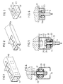
- the section 10 according to FIG. 1 is formed by a square hollow profile, while the section 10a according to FIG. 2 is a rectangular profile with an aspect ratio of approximately 2: 1, ie approximately half the height of the profile 10.
- the hollow profiles 10 and 10a are provided on one side with a longitudinal slot 11, while the opposite side has openings 12; in the rectangular profile 10a there are longitudinal slots and perforations on the longer sides of the rectangle.
- the square profile 10 can also have corresponding openings on the two other profile sides, as indicated by dash-dotted lines in FIG. 1. For certain purposes, it may be sufficient that only the two end regions of a profile section have openings 12, as can be seen from FIG. 2.
- Such profile sections can be fastened in a manner known per se by means of connecting bolts to ceilings, walls, pillars, etc., or can also be connected to one another, in order to build up assembly devices of various shapes or to suspend or mount pipes, conduit ducts, apparatuses, etc.
- insulating elements 20 can be used in the hollow profiles, electrical insulation between the profile sections and connecting bolts being achieved at the same time.
- Such an insulating element 20 has a preferably cuboid (or also cylindrical) body made of rubber-elastic material with a through hole 21.
- a support washer 24, for example made of steel, is provided opposite the support surface 22 and is firmly connected to the rubber-elastic body of the insulation element.
- the support disk 24 expediently has an opening 25 which corresponds to the shape of the extension 23 (see FIG. 5, only indicated in FIG. 3).
- the profiles 10, 10a and the insulation elements 20 are coordinated with one another in a special way with their attachment 23;
- the projection 23 can optionally engage in the longitudinal slot 11 or one of the perforations 12 of a profile section, wherein it is guided in the slot 11 so as to be longitudinally displaceable, but is fixed in position in the aperture 12 in question.
- the openings 12 and the extension 23 are preferably square, as shown, the length of the square side corresponding to the width of the slot 11, but positional fixation and rotation lock could in principle also be achieved in other ways, for example with rectangular or hexagonal openings or approaches.
- a profile section 10 is fastened sound-insulated to a threaded bolt 2 anchored in the building structure, using an insulating element 20 and also an insulating washer 30.
- the perforated insulating washer 30 has a layer made of rubber-elastic material and a metallic washer and serves as a counterhold on the profile 10 opposite the bearing surface 22 of the insulating element.
- the projection 23 of the insulating element engages in a perforation 12 in a fixed position, and the longitudinal slot 11 of the profile points downward.
- profile 10 rotated through 180 ° about the longitudinal axis
- lug 23 engaging slidably in longitudinal slot 11
- the longitudinal slot 11 would be directed to one side.
- the profile section 10 is fastened "hard” to the structure, for example by means of screws 3 which are passed through openings 12.
- a connecting bolt 4 here in the form of a hammer head screw, sound-insulated from the profile section 10 using an insulating element 20 and an insulating disk 30, the bolt in the slot 4 being adjustable in the longitudinal direction.
- individually insulated, position-adjustable fastenings can thus be formed, but other system parts can also be fastened directly to the profile section 10 without an insulating element.
- the hammer head 5 has a short, square projection, which engages in the corresponding recess 25 on the support disk 24.
- the insulating element 20 Since the insulating element 20 is secured against rotation via its extension 23 on the profile section 10 and also the hammer head 5 with respect to the insulating element 20, the tightening of the screw nut on the bolt 4 and the screwing of further parts on the connecting bolt 4 is facilitated.
- the rectangular profile section 10a according to FIG. 6 is in turn directly attached to the structure (by means of bolts that are not visible in a plane offset from the plane of the drawing).
- a connecting bolt 6 in the form of a carriage bolt is suspended from the insulating element 20 on the profile section 10a in a sound-insulated manner.
- the bolt 6 with the insulating element 20 is displaceable along the slot 11, the insulating element being secured against rotation; the lock screw in turn is also secured against rotation thanks to the square 7 adjoining the screw head, which presses into the rubber-elastic material.
- a synthetic rubber for example “neoprene”, is particularly suitable as the rubber-elastic material for the insulating element 20 and also for the insulating disk 30, and the Shore hardness of the material can be selected depending on the load or permissible deflection.
- insulation elements 20 can also be used on one and the same connecting bolt.
- the insulation elements can be arranged in a row (shoulder 23 of one element engaging in recess 25 of the other) or on the profile opposite one another (shoulder 23 of two elements engaging in the same opening 12 or in slot 11).
Landscapes
- Engineering & Computer Science (AREA)
- Architecture (AREA)
- Civil Engineering (AREA)
- Structural Engineering (AREA)
- General Engineering & Computer Science (AREA)
- Mechanical Engineering (AREA)
- Physics & Mathematics (AREA)
- Electromagnetism (AREA)
- Building Environments (AREA)
- Vibration Prevention Devices (AREA)
- Soundproofing, Sound Blocking, And Sound Damping (AREA)
- Joining Of Building Structures In Genera (AREA)
Description
- Die Erfindung betrifft eine Abhänge- und Montagevorrichtung mit Vierkant-Hohlprofilabschnitten, die zur Befestigung an Decken, Wänden oder untereinander mittels Verbindungsbolzen und sich innen am Profil abstützenden Dämmelementen bestimmt sind, wobei die Verbindungsblöcke eine einen Verbindungsbolzen aufnehmende Durchgangsbohrung und einen diese umgebenden, vorstehenden Ansatz aufweisen und wobei das Vierkant-Hohlprofil an der einen Seite einen Längsschlitz und mindestens an der gegenüberliegenden Seite Durchbrechungen aufweist.
- Vorrichtungen dieser Art werden vor allem in der Haustechnik verwendet, beispielsweise für die Verlegung von Leitungen aller Art, für die Befestigung von Apparaten und Maschinen, für den Schalttafelbau, zum Aufbau von Regalen usw. Oft wird dabei eine schallisolierende Aufhängung bzw. Befestigung von Apparaten und/oder Leitungen gefordert. Nach bisheriger Praxis ist dies relativ umständlich, indem die Schalldämmung am Einzelobjekt mittels verschiedenartigen und auf den jeweiligen Anwendungsfall ausgerichteten Befestigungselementen erfolgt.
- Aus der DE-A-2 150 566 ist eine Montagevorrichtung der eingangs genannten Art bekannt, die zur Befestigung von Wandverkleidungselementen an Raumwänden dient. Dabei ist ein Schallschutz durch die Verkleidungselemente selbst gegeben; die Montageteile - Profile, Verbindungsblöcke als Dämmelemente zur Wärmedämmung und Bolzen - sollen dagegen eine bequeme Befestigung und genaue Ausrichtung der Verkleidungselemente ermöglichen, ohne jedoch zur Schalldämmung beizutragen.
- Ziel der Erfindung ist die Schaffung einer Abhänge- und Montagevorrichtung, welche vielfältige Möglichkeiten der schallisolierten Montage und Installation mit möglichst wenigen, standardisierten Einzelteilen bietet.
- Diese Aufgabe wird erfindungsgemäss dadurch gelöst, dass zwecks Schallisolierung die Dämmelemente aus gummielastischem Material ausgebildet sind, und dass der über eine Profil-Auflagefläche der Dämmelemente vorstehende Ansatz sowie der Längsschlitz und die Durchbrechungen des Profils so aufeinander abgestimmt sind, dass der Ansatz einerseits im Schlitz längsverschiebbar geführt ist und anderseits auch lagefixierend in die Durchbrechungen passt. Indem das Profil und die Dämmelemente erfindungsgemäss aufeinander abgestimmt sind, entsteht ein einheitliches System, welches in sich selbst dem Erfordernis der Schallisolation gerecht wird. Insbesondere können - unter Verwendung der gleichen Einzelteile - tragende Systemteile wahlweise entweder schallgedämmt am Baukörper (Wände, Decken, Böden) befestigt werden, oder es können Rohre, Apparate usw. schallgedämmt an Systemteilen abgehängt bzw. montiert werden, die am Baukörper "hart" befestigt sind.
- In den Patentansprüchen 2 und 3 sind besondere, zweckmässige Ausgestaltungen der erfindungsgemässen Vorrichtung angegegben. Die Erfindung bezieht sich ausserdem auf ein Dämmelement nach Anspruch 4, das im Hinblick auf die Vorrichtung besonders ausgestaltet ist.
- Nachstehend werden Ausführungsbeispiele der Erfindung im Zusammenhang mit der Zeichnung im einzelnen beschrieben.
- Fig. 1 und Fig. 2
- zeigen zwei verschiedene Vierkant-Hohlprofilabschnitte in perspektivischer Darstellung,
- Fig. 3
- zeigt ein Dämmelement, ebenfalls perspektivisch, in etwas grösserem Massstab,
- Fig. 4, 5 und 6
- zeigen verschiedene Montagevarianten unter Verwendung der Teile nach den Fig. 1-3, jeweils als Schnitt quer durch das Hohlprofil auf der Höhe eines Verbindungsbolzens.
- In den Fig. 1 und 2 sind zwei verschiedene Vierkant-Hohlprofilabschnitte 10 bzw. 10a abgebrochen dargestellt, die beide zur Verwendung in einer Abhänge- und Montagevorrichtung bestimmt sind. Der Abschnitt 10 nach Fig. 1 ist durch ein quadratisches Hohlprofil gebildet, während es sich beim Abschnitt 10a nach Fig. 2 um ein Rechteckprofil mit einem Seitenverhältnis von etwa 2:1, also von etwa der halben Höhe des Profils 10 handelt. Die Hohlprofile 10 und 10a sind an der einen Seite mit einem Längsschlitz 11 versehen, während die gegenüberliegende Seite Durchbrechungen 12 aufweist; beim Rechteckprofil 10a befinden sich Längsschlitz und Durchbrechungen je an den längeren Rechteckseiten. Vor allem das quadratische Profil 10 kann auch an den beiden übrigen Profilseiten entsprechende Durchbrechungen aufweisen, wie in Fig. 1 strichpunktiert angedeutet ist. Für gewisse Verwendungszwecke kann es ausreichen, dass nur die beiden Endbereiche eines Profilabschnittes Durchbrechungen 12 aufweisen, wie dies aus Fig. 2 hervorgeht.
- Solche Profilabschnitte lassen sich in an sich bekannter Weise mittels Verbindungsbolzen an Decken, Wänden, Pfeilern usw. befestigen oder auch untereinander verbinden, um Montagevorrichtungen verschiedenster Gestalt aufzubauen oder Rohre, Leitungskanäle, Apparate usw. abzuhängen bzw. zu montieren.
- Zwecks schallisolierender Befestigung bzw. Verbindung werden in die Hohlprofile einsetzbare Dämmelemente 20 gemäss Fig. 3 verwendet, wobei gleichzeitig eine elektrische Isolierung zwischen Profilabschnitten und Verbindungsbolzen erreicht wird. Ein solches Dämmelement 20 weist einen vorzugsweise quaderförmigen (oder auch zylindrischen) Körper aus gummielastischem Material mit einer Durchgangsbohrung 21 auf. Ueber eine Profil-Auflagefläche 22 des Dämmelementes steht ein Ansatz 23 vor, welcher die Bohrung 21 umgibt. Der Auflagefläche 22 gegenüberliegend ist eine Auflagescheibe 24, z.B. aus Stahl, vorgesehen, welche mit dem gummielastischen Körper des Dämmelementes fest verbunden ist. Zweckmässigerweise weist die Auflagescheibe 24 eine Durchbrechung 25 auf, welche der Gestalt des Ansatzes 23 entspricht (siehe Fig. 5, in Fig. 3 nur angedeutet).
- Wie aus den Befestigungsbeispielen nach Fig. 4, 5 und 6 im einzelnen hervorgeht, sind die Profile 10, 10a und die Dämmelemente 20 mit ihrem Ansatz 23 in besonderer Weise aufeinander abgestimmt; der Ansatz 23 kann wahlweise in den Längsschlitz 11 oder eine der Druchbrechungen 12 eines Profilabschnittes eingreifen, wobei er im Schlitz 11 längsverschiebbar geführt, in der betreffenden Durchbrechung 12 jedoch lagefixiert ist. Es ist zweckmässig, wenn der erwähnte Eingriff des Ansatzes 23 drehgesichert erfolgt; vorzugsweise sind die Durchbrechungen 12 und der Ansatz 23, wie dargestellt, quadratisch, wobei die Länge der Quadratseite der Breite des Schlitzes 11 entspricht, jedoch könnten Lagefixierung und Drehsicherung grundsätzlich auch auf andere Weise, beispielsweise mit rechteckförmigen oder sechseckigen Durchbrechungen bzw. Ansätzen erreicht werden.
- Beim Montagebeispiel nach Fig. 4 ist ein Profilabschnitt 10 an einem im Baukörper verankerten Gewindebolzen 2 schallisoliert befestigt, unter Verwendung eines Dämmelementes 20 und ferner einer Dämmscheibe 30. Die durchbohrte Dämmscheibe 30 weist eine Lage aus gummielastischem Material und eine metallische Auflagescheibe auf und dient als Gegenhaltung am Profil 10 gegenüber der Auflagefläche 22 des Dämmelementes. Beim dargestellten Beispiel greift der Ansatz 23 des Dämmelementes lagefixiert in eine Durchbrechung 12 ein, und der Längsschlitz 11 des Profils weist nach unten. Selbstverständlich wäre auch eine Montage mit um 180° um die Längsachse gedrehtem Profil 10 möglich, wobei der Ansatz 23 in den Längsschlitz 11 verschiebbar eingreifen würde, oder - falls das Profil auch an den beiden übrigen Seiten Durchbrechungen aufweist - mit um 90° gedrehtem Profil, wobei der Längsschlitz 11 nach einer Seite gerichtet wäre. Bei dieser Montageart sind sämtliche am Profilabschnitt 10 befestigten bzw. abgehängten Teile wie Apparate, Rohrschellen, weitere Profilabschnitte usw. gegenüber dem Baukörper schallisoliert.
- Beim Beispiel nach Fig. 5 ist der Profilabschnitt 10 z.B. mittels Schrauben 3, welche durch Durchbrechungen 12 hindurchgeführt sind, am Baukörper "hart" befestigt. Dagegen ist ein Verbindungsbolzen 4, hier in Form einer Hammerkopfschraube, unter Verwendung eines Dämmelementes 20 und einer Dämmscheibe 30 schallisoliert am Profilabschnitt 10 abgehängt, wobei der Bolzen im Schlitz 4 in Längsrichtung einstellbar ist. Es können also bei dieser Montageart einzeln isolierte, lageeinstellbare Befestigungen gebildet werden, im übrigen aber auch andere Systemteile am Profilabschnitt 10 direkt, ohne Dämmelement, befestigt werden. Wie in Fig. 5 erkennbar, weist der Hammerkopf 5 einen kurzen, quadratischen Ansatz auf, welcher in die entsprechende Ausnehmung 25 an der Auflagescheibe 24 eingreift. Indem das Dämmelement 20 über seinen Ansatz 23 am Profilabschnitt 10 und ferner der Hammerkopf 5 gegenüber dem Dämmelement 20 drehgesichert ist, wird das Festziehen der Schraubenmutter auf dem Bolzen 4 sowie das Festschrauben weiterer Teile am Verbindungsbolzen 4 erleichtert.
- Der rechteckige Profilabschnitt 10a nach Fig. 6 ist wiederum am Baukörper direkt befestigt (mittels nicht sichtbaren Bolzen in einer zur Zeichenebene versetzten Ebene). Am Profilabschnitt 10a ist ein Verbindungsbolzen 6 in Form einer Schlossschraube über das Dämmelement 20 schallisoliert abgehängt. Der Bolzen 6 mit dem Dämmelement 20 ist entlang dem Schlitz 11 verschiebbar, wobei das Dämmelement drehgesichert ist; die Schlossschraube ihrerseits ist ebenfalls drehgesichert dank dem an den Schraubenkopf anschliessenden Vierkant 7, welcher sich in das gummielastische Material einpresst.
- Als gummielastisches Material für das Dämmelement 20 wie auch für die Dämmscheibe 30 eignet sich insbesondere ein synthetischer Kautschuk, beispielsweise "Neopren", wobei der Shore-Härtegrad des Materials je nach Belastung bzw. zulässiger Einfederung gewählt werden kann.
- Ueber die Beispiele nach Fig. 4 bis 6 hinaus bestehen natürlich - bei Verwendung immer gleicher, einfacher und aufeinander abgestimmter Teile - noch zahlreiche weitere, nicht dargestellte Kombinations- bzw. Montagemöglichkeiten. Insbesondere können auf einem und demselben Verbindungsbolzen auch zwei (oder gar mehrere) Dämmelemente 20 verwendet werden. Dabei können die Dämmelemente aneinandergereiht (Ansatz 23 des einen Elementes in die Ausnehmung 25 des anderen eingreifend) oder am Profil einander gegenüberliegend (Ansätze 23 zweier Elemente in die gleiche Durchbrechung 12 oder in den Schlitz 11 eingreifend) angeordnet werden. Durch Variieren der Anordnung und/oder der Härtegrade lassen sich je nach Anforderung stark unterschiedliche Dämmcharakteristiken erreichen.
Claims (4)
- Abhänge- und Montagevorrichtung mit Vierkant-Hohlprofilabschnitten, die zur Befestigung an Decken, Wänden oder untereinander mittels Verbindungsbolzen (2, 4, 6) und sich innen am Profil abstützenden Dämmelementen (20) bestimmt sind, wobei die Verbindungsblöcke eine einen Verbindungsbolzen aufnehmende Durchgangsbohrung (21) und einen diese umgebenden, vorstehenden Ansatz (23) aufweisen und wobei das Vierkant-Hohlprofil (10, 10a) an der einen Seite einen Längsschlitz (11) und mindestens an der gegenüberliegenden Seite Durchbrechungen (12) aufweist, dadurch gekennzeichnet, dass zwecks Schallisolierung die Dämmelemente (20) aus gummielastischem Material ausgebildet sind, und dass der über eine Profil-Auflagefläche (22) der Dämmelemente (20) vorstehende Ansatz (23) sowie der Längsschlitz (11) und die Durchbrechungen (12) des Profils (10, 10a) so aufeinander abgestimmt sind, dass der Ansatz (23) einerseits im Schlitz längsverschiebbar geführt ist und anderseits auch lagefixierend in die Durchbrechungen (12) passt.
- Vorrichtung nach Anspruch 1, dadurch gekennzeichnet, dass der Ansatz (23) der Dämmelemente (20) drehgesichert in die Durchbrechungen (12) und den Längsschlitz (11) des Hohlprofils (10, 10a) eingreift.
- Vorrichtung nach Anspruch 1, dadurch gekennzeichnet, dass zwecks Gegenhaltung am Profil (10, 10a) gegenüber der Auflagefläche (22) der Dämmelemente (20) durchbohrte Dämmscheiben (30) vorgesehen sind.
- Dämmelement (20) für eine Abhänge- und Montagevorrichtung nach einem der Ansprüche 1 bis 3, mit einem gummielastischen Körper, einem mit diesem fest verbundenen metallischen Auflageteil (24) und einer dem Körper und dem Auflageteil gemeinsame Durchgangsbohrung (21), dadurch gekennzeichnet, dass der metallische Auflageteil eine flache Scheibe (24) ist, die einer vom gummielastischen Körper gebildeten Auflagefläche (22) gegenüberliegt und die eine die Durchgangsbohrung (21) umgebende Durchbrechung (25) aufweist, welche einem über die genannte Auflagefläche (22) vorstehenden Ansatz (23) entspricht.
Applications Claiming Priority (2)
| Application Number | Priority Date | Filing Date | Title |
|---|---|---|---|
| CH453/90 | 1990-02-13 | ||
| CH453/90A CH680464A5 (de) | 1990-02-13 | 1990-02-13 |
Publications (2)
| Publication Number | Publication Date |
|---|---|
| EP0442243A1 EP0442243A1 (de) | 1991-08-21 |
| EP0442243B1 true EP0442243B1 (de) | 1993-09-29 |
Family
ID=4187374
Family Applications (1)
| Application Number | Title | Priority Date | Filing Date |
|---|---|---|---|
| EP90811038A Expired - Lifetime EP0442243B1 (de) | 1990-02-13 | 1990-12-28 | Abhänge- und Montagevorrichtung |
Country Status (6)
| Country | Link |
|---|---|
| US (1) | US5118069A (de) |
| EP (1) | EP0442243B1 (de) |
| JP (1) | JPH04213643A (de) |
| BR (1) | BR9100471A (de) |
| CH (1) | CH680464A5 (de) |
| DE (1) | DE59002947D1 (de) |
Families Citing this family (28)
| Publication number | Priority date | Publication date | Assignee | Title |
|---|---|---|---|---|
| DE9307288U1 (de) * | 1993-05-13 | 1994-09-29 | Fischerwerke Artur Fischer Gmbh & Co Kg, 72178 Waldachtal | Schallabsorbierende Befestigung, insbesondere für abgehängte Decken, Rohre u.dgl. |
| DE19612275C2 (de) * | 1996-03-28 | 1999-04-15 | Hilti Ag | Montageschiene |
| DE29703027U1 (de) * | 1997-02-20 | 1998-06-18 | Fischerwerke Artur Fischer Gmbh & Co Kg, 72178 Waldachtal | Hammerkopfschraube für eine Deckenbefestigung |
| US6996904B1 (en) | 1997-12-08 | 2006-02-14 | Micron Technology, Inc. | Method for managing cables |
| US6012683A (en) * | 1997-12-08 | 2000-01-11 | Micron Technology, Inc. | Apparatus for managing cables |
| AT406174B (de) * | 1998-05-25 | 2000-03-27 | Helmut Oberdorfer | Befestigungsteil für profile |
| ES2168917B1 (es) * | 1999-11-04 | 2003-05-16 | Maiztarkoetxea S L | Dispositivo de suspension elastica de perfiles para falsos techos. |
| DE20120077U1 (de) * | 2001-12-12 | 2002-05-23 | Heinzelmann, Rolf, 72760 Reutlingen | Vorrichtung zur Befestigung von Gegenständen, insbesondere von Rohren, unter Decken |
| US7125506B2 (en) * | 2004-06-21 | 2006-10-24 | Aco Polymer Products, Inc. | Drainage channel installation device |
| GB2446640B (en) * | 2007-02-14 | 2011-06-01 | John Graham Bryant | Attenuator |
| DE102007000296A1 (de) * | 2007-05-30 | 2008-12-04 | Hilti Aktiengesellschaft | Profilschiene |
| US8480041B2 (en) * | 2009-05-27 | 2013-07-09 | Philip Allen Myers | Beam clamp |
| NO333025B1 (no) * | 2009-09-02 | 2013-02-18 | Oglaend System As | Anordning ved langstrakt profil |
| CA2796836C (en) * | 2010-05-19 | 2015-09-29 | J. Van Walraven Holding B.V. | Profile element |
| US8661747B2 (en) * | 2010-07-23 | 2014-03-04 | Kristian Eide | Solar panel racking system |
| US9038344B2 (en) * | 2011-08-26 | 2015-05-26 | Hunter Douglas Inc. | Suspension ceiling with parallel vanes for building structures |
| ITBZ20120028A1 (it) | 2012-07-19 | 2014-01-20 | Rotho Blaas Srl Gmbh | Un elemento per il collegamento di componenti di costruzione in particolare pannelli e travi |
| DE212013000308U1 (de) * | 2013-08-29 | 2016-04-20 | J. Van Walraven Holding B.V. | Befestigungssystem |
| US9809972B2 (en) | 2014-01-16 | 2017-11-07 | Rotho Blaas Srl Gmbh | Element for the connection of building components, particularly panels and beams |
| JP6396776B2 (ja) * | 2014-12-03 | 2018-09-26 | 株式会社ニチベイ | 移動間仕切用防振装置 |
| ES2611972A1 (es) * | 2015-11-10 | 2017-05-11 | Maiztarkoetxea S.L. | Dispositivo de suspensión anti-vibratoria de paneles de pared y techo |
| US10677388B2 (en) * | 2017-04-14 | 2020-06-09 | Hall Labs Llc | Overhead mounting system and attachments |
| RU2762131C2 (ru) * | 2017-06-07 | 2021-12-16 | Жауме КОЛОМ ТАЛЬО | Строительная система для облицовки стен |
| CN110469021B (zh) * | 2019-08-17 | 2021-06-01 | 杭州得地新型建材有限公司 | 一种建筑用u型轻钢龙骨 |
| US11825789B2 (en) * | 2019-08-21 | 2023-11-28 | Dynaforge Trading Llc | Board connector system and method |
| US11913234B2 (en) | 2021-08-31 | 2024-02-27 | 0776425 B.C. Ltd. | Cladding attachment devices, systems, and associated methods of manufacture and use |
| US11933053B2 (en) * | 2022-03-25 | 2024-03-19 | 0776425 B.C. Ltd. | Cladding attachment devices, systems, and associated methods of use |
| US20250283519A1 (en) * | 2024-03-05 | 2025-09-11 | Pliteq Inc. | Vibration isolation hanger |
Family Cites Families (13)
| Publication number | Priority date | Publication date | Assignee | Title |
|---|---|---|---|---|
| FR845467A (fr) * | 1938-04-29 | 1939-08-24 | Plafonds Et Lattis Christin So | Dispositif de montage de plafonds, notamment de plafonds insonores et isolants |
| US2273571A (en) * | 1938-11-23 | 1942-02-17 | Cleveland Switchboard Company | Pipe hanger |
| US2308969A (en) * | 1941-06-10 | 1943-01-19 | Firestone Tire & Rubber Co | Resilient mounting |
| US2879090A (en) * | 1957-05-24 | 1959-03-24 | Gen Motors Corp | Resilient mounting means for absorbing axial and lateral thrusts |
| US3477216A (en) * | 1967-02-24 | 1969-11-11 | Jack L Martin | Suspension shock absorber for tree shaking devices |
| DE2150566A1 (de) * | 1971-10-11 | 1973-04-19 | Dura Tufting Gmbh | Vorgefertigtes wandverkleidungselement fuer rauminnenflaechen und anordnung zu seiner montage |
| US3854684A (en) * | 1973-01-04 | 1974-12-17 | A Moore | Support bracket |
| DE2364816A1 (de) * | 1973-12-28 | 1975-07-10 | Stig Loevgren | Federungselement |
| DE2617116A1 (de) * | 1976-04-17 | 1977-10-27 | Dieter Roempler | Aufhaengevorrichtung |
| US4638966A (en) * | 1985-06-21 | 1987-01-27 | Robroy Industries | Support member for hanging cable |
| US4662590A (en) * | 1986-05-05 | 1987-05-05 | Hungerford Charles S Jr | Connector device for supporting a conduct in a flanged channel |
| US4858880A (en) * | 1987-05-29 | 1989-08-22 | Caterpillar Inc. | Resilient load supporting and motion accommodating mounting apparatus |
| DE8715256U1 (de) * | 1987-11-06 | 1988-03-03 | Maro Befestigungs- und Verbindungstechnik GmbH, 7257 Ditzingen | Montageschieneneinheit |
-
1990
- 1990-02-13 CH CH453/90A patent/CH680464A5/de not_active IP Right Cessation
- 1990-12-28 EP EP90811038A patent/EP0442243B1/de not_active Expired - Lifetime
- 1990-12-28 DE DE90811038T patent/DE59002947D1/de not_active Expired - Fee Related
-
1991
- 1991-02-05 BR BR919100471A patent/BR9100471A/pt unknown
- 1991-02-12 US US07/655,320 patent/US5118069A/en not_active Expired - Fee Related
- 1991-02-12 JP JP3018800A patent/JPH04213643A/ja active Pending
Also Published As
| Publication number | Publication date |
|---|---|
| JPH04213643A (ja) | 1992-08-04 |
| DE59002947D1 (de) | 1993-11-04 |
| BR9100471A (pt) | 1991-10-29 |
| US5118069A (en) | 1992-06-02 |
| EP0442243A1 (de) | 1991-08-21 |
| CH680464A5 (de) | 1992-08-31 |
Similar Documents
| Publication | Publication Date | Title |
|---|---|---|
| EP0442243B1 (de) | Abhänge- und Montagevorrichtung | |
| DE20210133U1 (de) | Verbindung von Profilstreben | |
| DE1925350A1 (de) | Klammer zur Montage von Apparaturen auf Lochplatten | |
| CH598438A5 (en) | Clamp for facing and internal lining panels for wall or ceiling | |
| DE202014009445U1 (de) | Einstellbare Wandbefestigung für Plattenmaterialien | |
| EP0464367A1 (de) | Bauelementesatz zur Erstellung eines Tragwerks für Reinraumdecken | |
| EP1640524A2 (de) | Baukasten zum Erstellen einer Halterung insbesondere für Rohrleitungen | |
| DE202009011219U1 (de) | Verbindungsvorrichtung zwischen einem Decken- und Trennwandaufbau | |
| EP0444552A2 (de) | Befestigungskonsole für ein Fassadenbefestigungssystem | |
| DE19614942B4 (de) | Profilverbindung für unter Gehrung zusammenstoßende Profile | |
| EP0623530A1 (de) | Hängefördereinrichtung mit einem Montageprofilsatz | |
| DE4209516C1 (de) | ||
| DE19734601A1 (de) | Lochscheibe | |
| CH532726A (de) | Befestigungsvorrichtung | |
| DE202022101269U1 (de) | Befestigungssystem und Abdeckeinheit | |
| DE2336883C3 (de) | ||
| EP3306007B1 (de) | Montagesystem zur montage von lösbar zu befestigenden elementen an einer tragstruktur | |
| EP0816623B1 (de) | Profilelement zum Aufbau von Rahmen und Fassadenkonstruktionen | |
| EP0924358A2 (de) | Montageanker | |
| EP3889366B1 (de) | Befestigungsvorrichtung für eine sanitärtechnische anlage und montageverfahren | |
| DE102020209623B4 (de) | Montageplatte zur Wandmontage zumindest zweier Installationsfittings, Montagesystem sowie Verfahren zur Montage | |
| DE102021130484B4 (de) | Montageelement für den Innenausbau eines Schaltschrankgehäuses und eine entsprechende Schaltschrankanordnung | |
| DE2601023C3 (de) | Mehrteilige Kopplungs- und Justiereinrichtung für Fassadenelemente einer Vorhangwand o.dgl | |
| DE202024101757U1 (de) | Tragschiene | |
| EP1323933B1 (de) | Halterung für eine langgestreckte Profilschiene aus einem nach unten hin offenen C-Profil |
Legal Events
| Date | Code | Title | Description |
|---|---|---|---|
| PUAI | Public reference made under article 153(3) epc to a published international application that has entered the european phase |
Free format text: ORIGINAL CODE: 0009012 |
|
| AK | Designated contracting states |
Kind code of ref document: A1 Designated state(s): CH DE FR GB IT LI SE |
|
| RAP3 | Party data changed (applicant data changed or rights of an application transferred) |
Owner name: LANZ OENSINGEN AG |
|
| 17P | Request for examination filed |
Effective date: 19911009 |
|
| 17Q | First examination report despatched |
Effective date: 19920401 |
|
| GRAA | (expected) grant |
Free format text: ORIGINAL CODE: 0009210 |
|
| ITF | It: translation for a ep patent filed | ||
| AK | Designated contracting states |
Kind code of ref document: B1 Designated state(s): CH DE FR GB IT LI SE |
|
| REF | Corresponds to: |
Ref document number: 59002947 Country of ref document: DE Date of ref document: 19931104 |
|
| GBT | Gb: translation of ep patent filed (gb section 77(6)(a)/1977) |
Effective date: 19931026 |
|
| ET | Fr: translation filed | ||
| PLBE | No opposition filed within time limit |
Free format text: ORIGINAL CODE: 0009261 |
|
| STAA | Information on the status of an ep patent application or granted ep patent |
Free format text: STATUS: NO OPPOSITION FILED WITHIN TIME LIMIT |
|
| 26N | No opposition filed | ||
| PGFP | Annual fee paid to national office [announced via postgrant information from national office to epo] |
Ref country code: GB Payment date: 19941219 Year of fee payment: 5 |
|
| PGFP | Annual fee paid to national office [announced via postgrant information from national office to epo] |
Ref country code: SE Payment date: 19941222 Year of fee payment: 5 |
|
| EAL | Se: european patent in force in sweden |
Ref document number: 90811038.0 |
|
| PGFP | Annual fee paid to national office [announced via postgrant information from national office to epo] |
Ref country code: FR Payment date: 19951117 Year of fee payment: 6 |
|
| PGFP | Annual fee paid to national office [announced via postgrant information from national office to epo] |
Ref country code: DE Payment date: 19951221 Year of fee payment: 6 |
|
| PG25 | Lapsed in a contracting state [announced via postgrant information from national office to epo] |
Ref country code: GB Effective date: 19951228 |
|
| PG25 | Lapsed in a contracting state [announced via postgrant information from national office to epo] |
Ref country code: SE Effective date: 19951229 |
|
| PGFP | Annual fee paid to national office [announced via postgrant information from national office to epo] |
Ref country code: CH Payment date: 19960104 Year of fee payment: 6 |
|
| GBPC | Gb: european patent ceased through non-payment of renewal fee |
Effective date: 19951228 |
|
| PG25 | Lapsed in a contracting state [announced via postgrant information from national office to epo] |
Ref country code: LI Effective date: 19961231 Ref country code: CH Effective date: 19961231 |
|
| REG | Reference to a national code |
Ref country code: CH Ref legal event code: PL |
|
| PG25 | Lapsed in a contracting state [announced via postgrant information from national office to epo] |
Ref country code: FR Effective date: 19970829 |
|
| PG25 | Lapsed in a contracting state [announced via postgrant information from national office to epo] |
Ref country code: DE Effective date: 19970902 |
|
| REG | Reference to a national code |
Ref country code: FR Ref legal event code: ST |
|
| PG25 | Lapsed in a contracting state [announced via postgrant information from national office to epo] |
Ref country code: IT Free format text: LAPSE BECAUSE OF NON-PAYMENT OF DUE FEES Effective date: 20051228 |