EP0442255B1 - Moulage d'articles en matière plastique - Google Patents
Moulage d'articles en matière plastique Download PDFInfo
- Publication number
- EP0442255B1 EP0442255B1 EP91100013A EP91100013A EP0442255B1 EP 0442255 B1 EP0442255 B1 EP 0442255B1 EP 91100013 A EP91100013 A EP 91100013A EP 91100013 A EP91100013 A EP 91100013A EP 0442255 B1 EP0442255 B1 EP 0442255B1
- Authority
- EP
- European Patent Office
- Prior art keywords
- molten plastic
- mold cavity
- feeding
- nozzles
- mold
- Prior art date
- Legal status (The legal status is an assumption and is not a legal conclusion. Google has not performed a legal analysis and makes no representation as to the accuracy of the status listed.)
- Expired - Lifetime
Links
Images

Classifications
-
- B—PERFORMING OPERATIONS; TRANSPORTING
- B29—WORKING OF PLASTICS; WORKING OF SUBSTANCES IN A PLASTIC STATE IN GENERAL
- B29C—SHAPING OR JOINING OF PLASTICS; SHAPING OF MATERIAL IN A PLASTIC STATE, NOT OTHERWISE PROVIDED FOR; AFTER-TREATMENT OF THE SHAPED PRODUCTS, e.g. REPAIRING
- B29C45/00—Injection moulding, i.e. forcing the required volume of moulding material through a nozzle into a closed mould; Apparatus therefor
- B29C45/02—Transfer moulding, i.e. transferring the required volume of moulding material by a plunger from a "shot" cavity into a mould cavity
-
- B—PERFORMING OPERATIONS; TRANSPORTING
- B29—WORKING OF PLASTICS; WORKING OF SUBSTANCES IN A PLASTIC STATE IN GENERAL
- B29C—SHAPING OR JOINING OF PLASTICS; SHAPING OF MATERIAL IN A PLASTIC STATE, NOT OTHERWISE PROVIDED FOR; AFTER-TREATMENT OF THE SHAPED PRODUCTS, e.g. REPAIRING
- B29C45/00—Injection moulding, i.e. forcing the required volume of moulding material through a nozzle into a closed mould; Apparatus therefor
- B29C45/0005—Injection moulding, i.e. forcing the required volume of moulding material through a nozzle into a closed mould; Apparatus therefor using fibre reinforcements
-
- B—PERFORMING OPERATIONS; TRANSPORTING
- B29—WORKING OF PLASTICS; WORKING OF SUBSTANCES IN A PLASTIC STATE IN GENERAL
- B29C—SHAPING OR JOINING OF PLASTICS; SHAPING OF MATERIAL IN A PLASTIC STATE, NOT OTHERWISE PROVIDED FOR; AFTER-TREATMENT OF THE SHAPED PRODUCTS, e.g. REPAIRING
- B29C45/00—Injection moulding, i.e. forcing the required volume of moulding material through a nozzle into a closed mould; Apparatus therefor
- B29C45/0082—Reciprocating the moulding material inside the mould cavity, e.g. push-pull injection moulding
-
- B—PERFORMING OPERATIONS; TRANSPORTING
- B29—WORKING OF PLASTICS; WORKING OF SUBSTANCES IN A PLASTIC STATE IN GENERAL
- B29C—SHAPING OR JOINING OF PLASTICS; SHAPING OF MATERIAL IN A PLASTIC STATE, NOT OTHERWISE PROVIDED FOR; AFTER-TREATMENT OF THE SHAPED PRODUCTS, e.g. REPAIRING
- B29C45/00—Injection moulding, i.e. forcing the required volume of moulding material through a nozzle into a closed mould; Apparatus therefor
- B29C45/17—Component parts, details or accessories; Auxiliary operations
- B29C45/26—Moulds
- B29C45/27—Sprue channels ; Runner channels or runner nozzles
-
- B—PERFORMING OPERATIONS; TRANSPORTING
- B29—WORKING OF PLASTICS; WORKING OF SUBSTANCES IN A PLASTIC STATE IN GENERAL
- B29C—SHAPING OR JOINING OF PLASTICS; SHAPING OF MATERIAL IN A PLASTIC STATE, NOT OTHERWISE PROVIDED FOR; AFTER-TREATMENT OF THE SHAPED PRODUCTS, e.g. REPAIRING
- B29C45/00—Injection moulding, i.e. forcing the required volume of moulding material through a nozzle into a closed mould; Apparatus therefor
- B29C45/17—Component parts, details or accessories; Auxiliary operations
- B29C45/46—Means for plasticising or homogenising the moulding material or forcing it into the mould
-
- B—PERFORMING OPERATIONS; TRANSPORTING
- B29—WORKING OF PLASTICS; WORKING OF SUBSTANCES IN A PLASTIC STATE IN GENERAL
- B29C—SHAPING OR JOINING OF PLASTICS; SHAPING OF MATERIAL IN A PLASTIC STATE, NOT OTHERWISE PROVIDED FOR; AFTER-TREATMENT OF THE SHAPED PRODUCTS, e.g. REPAIRING
- B29C45/00—Injection moulding, i.e. forcing the required volume of moulding material through a nozzle into a closed mould; Apparatus therefor
- B29C45/17—Component parts, details or accessories; Auxiliary operations
- B29C45/26—Moulds
- B29C45/27—Sprue channels ; Runner channels or runner nozzles
- B29C45/28—Closure devices therefor
- B29C45/2806—Closure devices therefor consisting of needle valve systems
Definitions
- the present invention relates to injection molding fiber reinforced and non-reinforced resins especially in multi-cavity molds.
- Oscillation is particularly desirable in fiber reinforced resins in order to obtain uniform properties in the molded article.
- oscillation of the resin in the mold cavity is also desirable in non-reinforced resins in order to obtain the desired product uniformity.
- the pistons operate in an alternate manner to effectively oscillate the resin inside the mold cavity in order to orient the fibers or molecules.
- European Published Patent Application 0.339.184 to Gutjahr shows a similar process; however, the oscillation of the resin in the mold cavity is performed by the injection-plasticizing units themselves. In this case, two such units are required and the resin is supplied to the mold directly through cold sprues and runners. It is a disadvantage of the Gutjahr procedure that premature freezing of the melt is more likely since cold runners are being used. Also, the Gutjahr process requires two injection-plasticizing units which involves additional cost.
- a disadvantage of both of the foregoing procedures is the fact that they involve a single mold cavity. It is clearly desirable to utilize injection molding with oscillation in the mold cavity and with a plurality of mold cavities especially fed from a single feeding means or injection-plasticizing unit. The procedures of both of the foregoing references are not readily adaptable to use in a multi-cavity mold which is a significant disadvantage.
- U.S. Patent 4,717,324 and 4,863,369 both to Schad and Brown, show a hot runner system for a mold including shooting pots individual to each mold cavity for feeding precisely measured quantities of thermal plastic materials to each cavity.
- the apparatus of the present invention comprises: at least one mold cavity; at least two nozzles communicating with said mold cavity for feeding molten plastic to said mold cavity; a hot runner system communicating with said nozzles for feeding molten plastic to said nozzles; feeding means for feeding molten plastic to said hot runner system; valve means in said hot runner system operative to permit the flow of molten plastic to said nozzles from said feeding means and to shut-off the flow of molten plastic to said nozzles from said feeding means; at least one shooting pot communicating with each nozzle and with the hot runner system downstream of said valve means; and means for alternately feeding molten plastic from each shooting pot to the nozzle associated therewith whereby the molten plastic is oscillated in the mold cavity.
- At least two and generally a plurality of mold cavities are provided with at least two nozzles communicating with each cavity and shooting pots communicating with each nozzle, wherein a single feeding means is provided for feeding molten plastic to the hot runner system.
- the nozzles communicating with each mold cavity are located at opposite ends of each mold cavity.
- the method of the present invention comprises: feeding molten plastic from a feeding means to at least one mold cavity via a hot runner system and nozzles, wherein at least two nozzles communicate with each mold cavity; providing at least one shooting pot containing molten plastic communicating with each nozzle and with the mold cavity; discontinuing the flow of molten plastic from the feeding means to the mold cavities; and alternately feeding molten plastic from the shooting pots to the mold cavities while the flow of molten plastic to the mold cavities is discontinued, whereby the molten plastic is oscillated in the mold cavity.
- the molten plastic is alternately fed to a first shooting pot located at one end of the mold cavity followed by feeding molten plastic from a second shooting pot located at an opposed end of the mold cavity.
- the molten plastic is fed to the shooting pots via the feeding means and hot runner system simultaneously with feeding molten plastic from the feeding means and hot runner system to the mold cavity.
- the resin is effectively and conveniently oscillated in the mold cavity.
- the oscillation can be readily individually controlled for each cavity and the method and apparatus of the present invention is readily utilizable with a plurality of mold cavities fed from a single feeding means.
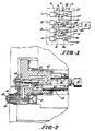
- an assembly A within the dashed lines includes a multi-cavity mold M in combination with a hot runner system S together with an external primary plastic compound feed unit 10 defining an extruder.
- Mold cavities 11, 12, 13 and 14 are connected individually to the hot runner system by nozzles (not shown in Figure 1) and compound conduits 15, 16, 17 and 18, respectively.
- nozzles not shown in Figure 1
- compound conduits 15, 16, 17 and 18, respectively any desired number of cavities may be employed and the molten plastic may or may not contain fibers to obtain a fiber reinforced molded article.
- Valves 19 , 20, 21 and 22 are provided controlling the introduction of molten plastic from extruder 10 and hot runner system S into cavities 11, 12, 13 and 14 and also into reservoirs 23, 24, 25 and 26 of shooting pots 27, 28, 29 and 30.
- the extruder 10 feeds both the mold cavities and the shooting pots.
- Figures 3 and 4 show the feature of the present invention of at least two shooting pots per mold cavity.
- Each valve is connected to hot runner system manifold 31 by compound conduits 32, 33, 34 and 35 and the manifold is in turn supplied molten plastic from extruder 10 via conduit 36.
- the shooting pots shown in Figure 1 define piston-cylinder assemblies where the stroke of each piston 37, 38, 39 and 40 is adjustable individually to change the volume of reservoirs 23, 24, 25 and 26 (cylinder portion) to facilitate feeding or metering precise quantities of plastic to the mold cavities on a cavity by cavity basis.
- valves 19, 20, 21 and 22 are closed, no further molten plastic can be fed from extruder 10 to the mold cavities and further feeding to the mold cavities is from the shooting pots.
- FIG 2 shows the details of a representative shooting pot within a hot runner system.
- Extruder 10 feeds molten plastic through channels 41 and 42 of hot runner manifold block 43 and through valve means 44 to charge reservoir 45 of shooting pot 46.
- molten plastic is fed via conduit 47 to the mold cavity (not shown in Figure 2) via nozzle 48 through nozzle passage 49.
- Nozzle stem 50 shown in the retracted position in Figure 2, is operated by piston 51 to open or close the nozzle passage.
- valve 44 is closed as shown in Figure 2 and further plastic in the precise quantity desired is charged to the mold cavity via the shooting pot until shooting pot piston 52 advances until it bottoms at bottom 53 of shooting pot cylinder 45.
- Valve stem 50 is then closed, the product removed and the cycle repeated.
- FIGs 3 and 4 show the detailed operation of the apparatus and method of the present invention.
- molten resin with or without fibers is injected from an injection-plasticizing unit (not shown in Figure 3) into the supply channel 60 of sprue bar 61 which in turn is connected to hot runner manifold 62.
- the supply channel 60 splits into as many sub-channels 63 as there are mold cavities.
- two mold cavities 64 and 64A there are shown two mold cavities 64 and 64A; however, it should be understood that any desired number of mold cavities of a multi-cavity system can readily be employed. It is a significant advantage of the present invention that multi-cavity systems can readily be used with the present invention.
- sub-channels 63 are bifurcated to supply molten resin to two or more cavities 64 via nozzles 65, 66, 67 and 68.
- each mold cavity has associated therewith two nozzles feeding resin from opposite ends of the mold cavity.
- mold cavity 64 is fed from nozzles 65 and 66 and mold cavity 64A is fed from nozzles 67 and 68.
- more than two nozzles per mold cavity can be used if desired, especially for complex parts.
- Each nozzle is provided with means for discontinuing resin flow into the mold, as by gates 69. The nozzles and the manifold are heated by heaters 70.
- a shooting pot having a construction as shown in Figures 1 and 2.
- Communicating with mold 64 is first shooting pot 71 and second shooting pot 72 located in manifold 62 at opposite ends of mold 64.
- the shooting pot 71 includes cavity 73 and piston assemblies 74 similar to that shown in Figure 2, and shooting pot 72 includes cavity 76 and piston assembly 77.
- Figure 4 shows piston 77 of second shooting pot 72 advanced and piston 74 of first shooting pot 71 retracted. This action is individual to each mold cavity since each mold cavity has two nozzles and two shooting pots associated therewith and these are isolated from neighboring cavities by shut-off valves 75. Naturally, the same action takes place at mold cavity 64A and the other mold cavities in the multi-cavity system.
- the resin in the mold cures and the mold is opened to eject the part. Meanwhile, the heaters 70 in the manifold and nozzles keep the resins molten and ready for the next cycle.
- the flow of molten plastic from the feeding means is discontinued to the mold cavities followed by alternately feeding molten plastic from the shooting pots to the mold cavities while the flow of molten plastic to the mold cavities is discontinued. This results in oscillation of the molten plastic in the mold cavities.
Landscapes
- Engineering & Computer Science (AREA)
- Manufacturing & Machinery (AREA)
- Mechanical Engineering (AREA)
- Moulds For Moulding Plastics Or The Like (AREA)
- Transition And Organic Metals Composition Catalysts For Addition Polymerization (AREA)
- Addition Polymer Or Copolymer, Post-Treatments, Or Chemical Modifications (AREA)
- Processing And Handling Of Plastics And Other Materials For Molding In General (AREA)
- Injection Moulding Of Plastics Or The Like (AREA)
- Toys (AREA)
Claims (14)
- Appareil pour mouler des articles en matière plastique, caractérisé en ce qu'il comprend :- au moins une cavité de moule (11, 12, 13, 14, 64, 64a) ;- au moins deux buses (48, 65, 66 ; 67, 68) communiquant avec la cavité de moule (11, 12, 13, 14, 64, 64a) pour fournir de la matière plastique en fusion à la cavité de moule ;- un système d'entraînement à chaud (S) communiquant avec les buses (48, 65, 66 ; 67, 68) pour fournir de la matière plastique en fusion à ces buses ;- des moyens d'alimentation (10) pour fournir de la matière plastique en fusion au système d'entraînement à chaud (S) ;- des moyens de soupape (19, 20, 21, 22, 44, 75) montés dans le système d'entraînement à chaud (S) pour permettre au débit de matière plastique en fusion de passer des moyens d'alimentation (10) aux buses (48, 65, 66 ; 67, 68), et pour couper le passage du débit de matière plastique en fusion entre les moyens d'alimentation (10) et les buses (48, 65, 66 ; 67, 68) ;- au moins un pot d'injection (27, 28, 29, 30, 46, 71, 72) communiquant avec chaque buse (48, 65, 66 ; 67, 68) et avec le système d'entraînement à chaud (S) en aval des moyens de soupape (19, 20, 21, 22, 44, 75) ; et- des moyens pour fournir alternativement la matière plastique en fusion provenant de chaque pot d'injection (27, 28, 29, 30, 46, 71, 72), à la buse (48, 65, 66 ; 67, 68) associée à celui-ci, ce qui permet ainsi de faire osciller la matière plastique en fusion dans la cavité de moule (11, 12, 13, 14, 64, 64a).
- Appareil selon la revendication 1, caractérisé en ce qu'il comprend au moins deux cavités de moule (11, 12, 13, 14, 64, 64a) avec au moins deux buses (48, 65, 66 ; 67, 68) communiquant avec chaque cavité (11, 12, 13, 14, 64, 64a), et pots d'injection (27, 28, 29, 30, 46, 71, 72) communiquant avec chaque buse (48, 65, 66 ; 67, 68), et en ce qu'il utilise un moyen d'alimentation (10) unique pour fournir la matière plastique en fusion au système d'entraînement à chaud (S).
- Appareil selon l'une quelconque des revendications 1 et 2, caractérisé en ce que la matière plastique en fusion comprend des fibres pour donner un article moulé renforcé par des fibres.
- Appareil selon l'une quelconque des revendications 1 à 3, caractérisé en ce qu'il comprend deux buses (65, 66 ; 67, 68) communiquant avec chaque cavité de moule (64, 64a) et placées aux extrémités opposées de chaque cavité de moule (64, 64a).
- Appareil selon l'une au moins des revendications 1 à 4, caractérisé en ce qu'il comprend des moyens de chauffage du système d'entraînement à chaud (S).
- Appareil selon l'une au moins des revendications 1 à 5, caractérisé en ce qu'il comprend des moyens (70) de chauffage des buses (65, 66 ; 67, 68).
- Appareil selon l'une au moins des revendications 1 à 6, caractérisé en ce que les moyens d'alimentation (10) servent à fournir simultanément de la matière plastique en fusion à la cavité de moule (11, 12, 13, 14, 64, 64a) et aux pots d'injection (27, 28, 29, 30, 46, 71, 72) par l'intermédiaire du système d'entraînement à chaud (S).
- Procédé de fabrication d'articles en matière plastique moulée, caractérisé en ce qu'il comprend les différentes étapes consistant à :- fournir de la matière plastique en fusion provenant d'un moyen d'alimentation (10), à au moins une cavité de moule (11, 12, 13, 14, 64, 64a) par l'intermédiaire d'un système d'entraînement à chaud (S) et de buses (48, 65, 66 ; 67, 68), dans lesquels au moins deux buses (65, 66 ; 67, 68) communiquent avec chaque cavité de moule (64, 64a) ;- utiliser au moins un pot d'injection (27, 28, 29, 30, 46, 71, 72) contenant de la matière plastique en fusion , de façon qu'il communique avec chaque buse (48, 65, 66 ; 67, 68) et avec la cavité de moule (11, 12, 13, 14, 64, 64a) ;- couper le débit de matière plastique en fusion allant du moyen d'alimentation (10) à la cavité de moule (11, 12, 13, 14, 64, 64a) ; et- fournir alternativement de la matière plastique en fusion provenant des pots d'injection (27, 28, 29, 30, 46, 71, 72), aux cavités de moule (11, 12, 13, 14, 64, 64a) pendant que le débit de matière plastique en fusion alimentant les cavités de moule (11, 12, 13, 14, 64, 64a) est coupé, de manière à faire osciller ainsi la matière plastique en fusion dans la cavité de moule (11, 12, 13, 14, 64, 64a).
- Procédé selon la revendication 8, caractérisé en ce que la matière plastique en fusion est alimentée alternativement par un premier pot d'injection (71) placé à une extrémité de la cavité de moule (64), puis ensuite par un second pot d'injection (72) placé à l'extrémité opposée de la cavité de moule (64).
- Procédé selon l'une quelconque des revendications 8 et 9, caractérisé en ce que le débit de matière plastique en fusion allant du moyen d'alimentation (10) à la cavité de moule (11, 12, 13, 14, 64, 64a) est coupé par des moyens de soupape (19, 20, 21, 22, 44, 75) placés en amont des pots d'injection (27, 28, 29, 30, 46, 71, 72).
- Procédé selon l'une quelconque des revendications 8 à 10, caractérisé en ce qu'on fournit la matière plastique en fusion aux pots d'injection (27, 28, 29, 30, 46, 71, 72) par l'intermédiaire des moyens d'alimentation (10) et du système d'entraînement à chaud (S), en même temps que cette matière plastique en fusion est fournie par le moyen d'alimentation (10) et le système d'entraînement à chaud (S), à la cavité de moule (11, 12, 13, 14, 64, 64a).
- Procédé selon l'une au moins des revendications 8 à 11, caractérisé en ce que des fibres sont comprises dans la matière plastique en fusion pour donner un article moulé renforcé par des fibres.
- Procédé selon l'une au moins des revendications 8 à 12, caractérisé en ce qu'il comprend les étapes consistant à chauffer le système d'entraînement à chaud (S) et/ou les buses (48, 65, 66 ; 67, 68).
- Procédé selon l'une au moins des revendications 8 à 13, caractérisé en ce qu'il comprend l'étape consistant à fournir la matière plastique en fusion provenant du moyen d'alimentation (10), à plusieurs cavités de moule (11, 12, 13, 14, 64, 64a).
Priority Applications (1)
| Application Number | Priority Date | Filing Date | Title |
|---|---|---|---|
| AT91100013T ATE95110T1 (de) | 1990-02-16 | 1991-01-02 | Formen von kunststoffgegenstaenden. |
Applications Claiming Priority (2)
| Application Number | Priority Date | Filing Date | Title |
|---|---|---|---|
| US07/480,866 US5069840A (en) | 1990-02-16 | 1990-02-16 | Molding plastic articles |
| US480866 | 1990-02-16 |
Publications (3)
| Publication Number | Publication Date |
|---|---|
| EP0442255A2 EP0442255A2 (fr) | 1991-08-21 |
| EP0442255A3 EP0442255A3 (en) | 1992-03-25 |
| EP0442255B1 true EP0442255B1 (fr) | 1993-09-29 |
Family
ID=23909658
Family Applications (1)
| Application Number | Title | Priority Date | Filing Date |
|---|---|---|---|
| EP91100013A Expired - Lifetime EP0442255B1 (fr) | 1990-02-16 | 1991-01-02 | Moulage d'articles en matière plastique |
Country Status (5)
| Country | Link |
|---|---|
| US (1) | US5069840A (fr) |
| EP (1) | EP0442255B1 (fr) |
| JP (1) | JPH0825211B2 (fr) |
| AT (1) | ATE95110T1 (fr) |
| DE (1) | DE69100408T2 (fr) |
Families Citing this family (38)
| Publication number | Priority date | Publication date | Assignee | Title |
|---|---|---|---|---|
| CA1243462A (fr) * | 1984-12-21 | 1988-10-25 | Peter S. Allan | Methode de moulage |
| US5260012A (en) * | 1990-02-16 | 1993-11-09 | Husky Injection Molding Systems Ltd. | Molding plastic articles |
| AT402278B (de) * | 1990-12-28 | 1997-03-25 | Sony Corp | Spritzgussvorrichtung zur herstellung von trägerschichten für optische platten |
| JP2708971B2 (ja) * | 1991-04-09 | 1998-02-04 | ポリプラスチックス株式会社 | 射出成形方法および射出成形用金型並びに射出成形品 |
| KR960007275B1 (ko) * | 1992-06-05 | 1996-05-30 | 폴리플라스틱스 가부시끼가이샤 | 사출성형방법. 사출성형용 주형 및 사출성형된 물건 |
| DE4221423C2 (de) * | 1992-06-30 | 2002-06-20 | Sig Corpoplast Gmbh & Co Kg | Verfahren und Vorrichtung zum Herstellen von Gegenständen aus thermoplastischem Kunststoff durch Spritzgießen |
| WO1995011122A1 (fr) * | 1993-10-18 | 1995-04-27 | Thermold Partners L.P. | Procede et dispositif de moulage par injection |
| DE735943T1 (de) * | 1993-12-22 | 1997-04-03 | Commer Spa | Verfahren und vorrichtung zum kospritzgiessen von gegenständen mit komplizierter form |
| US5766654A (en) * | 1994-02-18 | 1998-06-16 | Groleau; Rodney J. | Apparatus for improving knit line strength in polymeric materials |
| TW309465B (fr) * | 1995-07-05 | 1997-07-01 | Eastman Chem Co | |
| US5705201A (en) * | 1995-09-01 | 1998-01-06 | Ibar; Jean-Pierre | Apparatus for controlling gas assisted injection molding to produce hollow and non-hollow plastic parts and modify their physical characteristics |
| FR2741837B1 (fr) * | 1995-11-30 | 1998-02-27 | Inoplast Sa | Methode et dispositif de moulage par injection et piece en matiere composite obtenue par cette methode |
| US5770131A (en) * | 1996-01-02 | 1998-06-23 | Thermold Partners, L.P. | Method and apparatus for applying an oscillating force on a molten material |
| DE19632315C1 (de) * | 1996-08-10 | 1998-05-14 | Rudolf Goerlich | Verfahren und Vorrichtung zur gleichzeitigen Herstellung von Kleinstspritzgußteilen aus thermoplastischen oder vernetzenden Polymeren |
| US5922363A (en) * | 1997-04-07 | 1999-07-13 | Dtl Technology Limited Partnership | Molding multi-layered articles using coinjection techniques |
| US5971735A (en) * | 1997-04-09 | 1999-10-26 | Dtl Technology Limited Partnership | Coinjection molding or multi-layer articles |
| US6684030B1 (en) | 1997-07-29 | 2004-01-27 | Khamsin Technologies, Llc | Super-ring architecture and method to support high bandwidth digital “last mile” telecommunications systems for unlimited video addressability in hub/star local loop architectures |
| US6091025A (en) * | 1997-07-29 | 2000-07-18 | Khamsin Technologies, Llc | Electrically optimized hybird "last mile" telecommunications cable system |
| CA2306092C (fr) * | 1997-10-14 | 2002-05-07 | The Penn State Research Foundation | Procede et appareil pour controler l'orientation du flux dans un devidoir pour le remplissage ccontrole de moules |
| DE19801412C2 (de) * | 1998-01-16 | 2001-05-10 | Boy Gmbh Dr | Plastifizier- und Einspritzeinheit für eine Spritzgießmaschine |
| US6382946B1 (en) | 1998-04-01 | 2002-05-07 | Dtl Technology Limited Partnership | Molding multi-layered articles using coinjection techniques |
| US6239379B1 (en) | 1998-07-29 | 2001-05-29 | Khamsin Technologies Llc | Electrically optimized hybrid “last mile” telecommunications cable system |
| US6290882B1 (en) | 1999-06-07 | 2001-09-18 | Galic Maus Ventures Llp | Reduced-knitline thermoplastic injection molding using multi-gated non-sequential-fill method and apparatus, with a heating phase and a cooling phase in each molding cycle |
| KR100808960B1 (ko) * | 2000-02-24 | 2008-03-04 | 도레이 가부시끼가이샤 | 에프알피 성형품 및 그 제조방법 |
| US6503438B2 (en) | 2000-06-28 | 2003-01-07 | Beaumont Runner Technologies, Inc. | Method and apparatus for balancing flowing conditions of laminar flowing materials |
| DE10052841A1 (de) * | 2000-10-24 | 2002-04-25 | Keim Hans Joachim | Verfahren und Anlage zur Verarbeitung thermoplastischer Kunststoffe |
| JP2004114537A (ja) * | 2002-09-27 | 2004-04-15 | Daicel Chem Ind Ltd | 長繊維強化熱可塑性樹脂成形品及びその製造方法 |
| JP2004122440A (ja) * | 2002-09-30 | 2004-04-22 | Aoki Technical Laboratory Inc | 射出ブロー成形機の型締装置 |
| CA2443483C (fr) | 2002-10-02 | 2011-08-16 | Mold-Masters Limited | Dispositif melangeur |
| DE10307616A1 (de) * | 2003-02-22 | 2004-09-02 | Merck Patent Gmbh | Spritzeinheit zur Verarbeitung schmelzbarer Materialien |
| DE102004009320A1 (de) * | 2003-02-26 | 2004-11-18 | Mold-Masters Ltd., Georgetown | Heißläuferverteiler-Stopfen für einen rheologischen Ausgleich beim Heißläufer-Spritzgießen |
| US7559756B2 (en) * | 2004-06-30 | 2009-07-14 | Husky Injection Molding Systems, Ltd. | Apparatus and method for actuation of injection molding shooting pots |
| DE102005050360B4 (de) * | 2004-10-20 | 2015-11-05 | Mold-Masters (2007) Limited | Spritzgiessvorrichtung mit Seitenanguss |
| US7614872B2 (en) * | 2005-10-04 | 2009-11-10 | Mold-Masters (2007) Limited | Melt redistribution element for an injection molding apparatus |
| US7771190B2 (en) * | 2007-10-31 | 2010-08-10 | Husky Injection Molding Systems Ltd. | High pressure injection molding nozzle with low pressure manifold |
| US8007272B2 (en) * | 2007-10-31 | 2011-08-30 | Husky Injection Molding Systems Ltd. | Shooting pot for feeding multiple nozzles |
| EP2519393B1 (fr) | 2009-12-31 | 2015-04-08 | Husky Injection Molding Systems S.A. | Système de canal de coulée de moule comportant des ensembles de pot d'injection pouvant être commandés de façon indépendante |
| JP5735109B2 (ja) | 2010-08-13 | 2015-06-17 | グリーン, ツイード オブ デラウェア, インコーポレイテッド | 高体積繊維負荷を有する熱可塑性繊維複合材ならびにそれを作製するための方法および装置 |
Family Cites Families (12)
| Publication number | Priority date | Publication date | Assignee | Title |
|---|---|---|---|---|
| US3709644A (en) * | 1970-11-25 | 1973-01-09 | J Farrell | Time saver plastic draw-back valve assembly |
| CH538928A (de) * | 1971-06-14 | 1973-07-15 | Hanning Robert | Verfahren zum Herstellen von insbesondere grossflächigen Gegeständen durch Spritzgiessen eines Gemisches aus plasiziertem Kunststoff und einem Treibmittel und dafür geeignete Spritzgussmaschine |
| DE2321634A1 (de) * | 1973-04-28 | 1974-11-14 | Vowinckel Fa Joh J | Verfahren zum herstellen dickwandiger platten aus einem polyolefin |
| JPS53140361A (en) * | 1977-05-13 | 1978-12-07 | Hitachi Zosen Corp | Injection molding machine |
| WO1984004487A1 (fr) * | 1983-05-06 | 1984-11-22 | Noort Jacob Van | Procede, machine de moulage par injection et moule d'injection pour la fabrication d'objets en forme de conteneur, objets en forme de conteneur et systeme de canal de coulee chaude |
| US4925161B1 (en) * | 1984-12-21 | 1994-12-20 | British Tech Group | Process for molding directionally-orientable material using shear force |
| CA1243462A (fr) * | 1984-12-21 | 1988-10-25 | Peter S. Allan | Methode de moulage |
| EP0205710A3 (fr) * | 1985-06-17 | 1988-03-30 | Toyota Jidosha Kabushiki Kaisha | Dispositif de moulage par injection du type à multi-cylindres |
| US4717324A (en) * | 1986-05-12 | 1988-01-05 | Husky Injection Molding Systems, Inc. | Coinjection of hollow articles and preforms |
| US4863369A (en) * | 1986-05-12 | 1989-09-05 | Husky Injection Molding Systems Ltd. | Injection molding with shooting pots |
| US4722679A (en) * | 1986-06-13 | 1988-02-02 | Tri-Delta Technology, Inc. | Injection molding machine |
| DE3810954A1 (de) * | 1988-03-31 | 1989-10-19 | Kloeckner Ferromatik Desma | Verfahren und vorrichtung zum spritzgiessen von spritzgussteilen aus plastifizierbarem material, insbesondere aus plastifizierbaren fluessigkristall-polymeren |
-
1990
- 1990-02-16 US US07/480,866 patent/US5069840A/en not_active Expired - Lifetime
-
1991
- 1991-01-02 EP EP91100013A patent/EP0442255B1/fr not_active Expired - Lifetime
- 1991-01-02 AT AT91100013T patent/ATE95110T1/de not_active IP Right Cessation
- 1991-01-02 DE DE91100013T patent/DE69100408T2/de not_active Expired - Fee Related
- 1991-02-13 JP JP3041168A patent/JPH0825211B2/ja not_active Expired - Fee Related
Also Published As
| Publication number | Publication date |
|---|---|
| EP0442255A3 (en) | 1992-03-25 |
| JPH0825211B2 (ja) | 1996-03-13 |
| ATE95110T1 (de) | 1993-10-15 |
| DE69100408D1 (de) | 1993-11-04 |
| DE69100408T2 (de) | 1994-03-24 |
| US5069840A (en) | 1991-12-03 |
| EP0442255A2 (fr) | 1991-08-21 |
| JPH0768603A (ja) | 1995-03-14 |
Similar Documents
| Publication | Publication Date | Title |
|---|---|---|
| EP0442255B1 (fr) | Moulage d'articles en matière plastique | |
| US5192555A (en) | Apparatus for molding plastic articles | |
| US5260012A (en) | Molding plastic articles | |
| US4863369A (en) | Injection molding with shooting pots | |
| EP0393389B1 (fr) | Pot de transfert étagé pour le moulage par injection | |
| EP1762359B1 (fr) | Buse de co-injection à canaux chauffants | |
| CA2212599C (fr) | Procede et dispositif servant a la fabrication de pieces moulees par injection dans du plastique | |
| US3797984A (en) | Cold sprue injection molding device with integral sprue chamber and injection nozzle | |
| EP0013154B1 (fr) | Procédé et dispositif pour mouler sans carotte des matières thermodurcissables par injection-compression | |
| JP4368452B2 (ja) | 射出成形機、複数材料射出成形機、射出成形機用シューティングポット作動アセンブリ、及び複数材料射出成形機用シューティングポットアクチュエータ | |
| US5074772A (en) | Mold for injection molded parts made of plasticizable material | |
| EP2519393B1 (fr) | Système de canal de coulée de moule comportant des ensembles de pot d'injection pouvant être commandés de façon indépendante | |
| JPH0337494B2 (fr) | ||
| US6530777B1 (en) | Injection moulding machine with integrated hot channel system | |
| CA2440526A1 (fr) | Dispositif de dosage pour machine a mouler les matieres plastiques | |
| US4309379A (en) | Method and apparatus for runnerless injection-compression molding thermosetting materials | |
| CN102802903B (zh) | 带有集成熔融装置的模具组件 | |
| KR101653074B1 (ko) | 인젝션 몰딩을 위한 분배 시스템 | |
| US5087190A (en) | Multi plunger molding machine for liquid silicone rubber | |
| CN101312815B (zh) | 模制方法和设备 | |
| EP0013119B1 (fr) | Dispositif pour mouler sans carotte des matières thermodurcissables par injection-compression | |
| WO2012068681A1 (fr) | Système de moulage comprenant un ensemble pot d'injection et un ensemble vanne où la pression de maintien n'est pas fournie par l'ensemble pot d'injection | |
| AU2002226560A1 (en) | Metering device for a plastics moulding machine |
Legal Events
| Date | Code | Title | Description |
|---|---|---|---|
| PUAI | Public reference made under article 153(3) epc to a published international application that has entered the european phase |
Free format text: ORIGINAL CODE: 0009012 |
|
| AK | Designated contracting states |
Kind code of ref document: A2 Designated state(s): AT BE CH DE DK ES FR GB GR IT LI LU NL SE |
|
| PUAL | Search report despatched |
Free format text: ORIGINAL CODE: 0009013 |
|
| AK | Designated contracting states |
Kind code of ref document: A3 Designated state(s): AT BE CH DE DK ES FR GB GR IT LI LU NL SE |
|
| 17P | Request for examination filed |
Effective date: 19920408 |
|
| 17Q | First examination report despatched |
Effective date: 19921125 |
|
| GRAA | (expected) grant |
Free format text: ORIGINAL CODE: 0009210 |
|
| AK | Designated contracting states |
Kind code of ref document: B1 Designated state(s): AT BE CH DE DK ES FR GB GR IT LI LU NL SE |
|
| PG25 | Lapsed in a contracting state [announced via postgrant information from national office to epo] |
Ref country code: BE Effective date: 19930929 Ref country code: NL Effective date: 19930929 Ref country code: DK Effective date: 19930929 Ref country code: GR Free format text: LAPSE BECAUSE OF FAILURE TO SUBMIT A TRANSLATION OF THE DESCRIPTION OR TO PAY THE FEE WITHIN THE PRESCRIBED TIME-LIMIT Effective date: 19930929 Ref country code: ES Free format text: THE PATENT HAS BEEN ANNULLED BY A DECISION OF A NATIONAL AUTHORITY Effective date: 19930929 Ref country code: SE Effective date: 19930929 |
|
| REF | Corresponds to: |
Ref document number: 95110 Country of ref document: AT Date of ref document: 19931015 Kind code of ref document: T |
|
| REF | Corresponds to: |
Ref document number: 69100408 Country of ref document: DE Date of ref document: 19931104 |
|
| ITF | It: translation for a ep patent filed | ||
| REG | Reference to a national code |
Ref country code: CH Ref legal event code: PL |
|
| PG25 | Lapsed in a contracting state [announced via postgrant information from national office to epo] |
Ref country code: LU Free format text: LAPSE BECAUSE OF NON-PAYMENT OF DUE FEES Effective date: 19940131 |
|
| ET | Fr: translation filed | ||
| NLV1 | Nl: lapsed or annulled due to failure to fulfill the requirements of art. 29p and 29m of the patents act | ||
| REG | Reference to a national code |
Ref country code: CH Ref legal event code: AEN |
|
| PLBE | No opposition filed within time limit |
Free format text: ORIGINAL CODE: 0009261 |
|
| STAA | Information on the status of an ep patent application or granted ep patent |
Free format text: STATUS: NO OPPOSITION FILED WITHIN TIME LIMIT |
|
| 26N | No opposition filed | ||
| REG | Reference to a national code |
Ref country code: GB Ref legal event code: IF02 |
|
| REG | Reference to a national code |
Ref country code: CH Ref legal event code: NV Representative=s name: BOVARD AG PATENTANWAELTE |
|
| PGFP | Annual fee paid to national office [announced via postgrant information from national office to epo] |
Ref country code: CH Payment date: 20071130 Year of fee payment: 18 |
|
| PGFP | Annual fee paid to national office [announced via postgrant information from national office to epo] |
Ref country code: FR Payment date: 20071130 Year of fee payment: 18 Ref country code: GB Payment date: 20071130 Year of fee payment: 18 |
|
| PGFP | Annual fee paid to national office [announced via postgrant information from national office to epo] |
Ref country code: IT Payment date: 20080107 Year of fee payment: 18 Ref country code: DE Payment date: 20071129 Year of fee payment: 18 |
|
| PGFP | Annual fee paid to national office [announced via postgrant information from national office to epo] |
Ref country code: AT Payment date: 20071129 Year of fee payment: 18 |
|
| REG | Reference to a national code |
Ref country code: CH Ref legal event code: PL |
|
| GBPC | Gb: european patent ceased through non-payment of renewal fee |
Effective date: 20090102 |
|
| PG25 | Lapsed in a contracting state [announced via postgrant information from national office to epo] |
Ref country code: AT Free format text: LAPSE BECAUSE OF NON-PAYMENT OF DUE FEES Effective date: 20090102 Ref country code: LI Free format text: LAPSE BECAUSE OF NON-PAYMENT OF DUE FEES Effective date: 20090131 Ref country code: DE Free format text: LAPSE BECAUSE OF NON-PAYMENT OF DUE FEES Effective date: 20090801 Ref country code: CH Free format text: LAPSE BECAUSE OF NON-PAYMENT OF DUE FEES Effective date: 20090131 |
|
| REG | Reference to a national code |
Ref country code: FR Ref legal event code: ST Effective date: 20091030 |
|
| PG25 | Lapsed in a contracting state [announced via postgrant information from national office to epo] |
Ref country code: GB Free format text: LAPSE BECAUSE OF NON-PAYMENT OF DUE FEES Effective date: 20090102 |
|
| PG25 | Lapsed in a contracting state [announced via postgrant information from national office to epo] |
Ref country code: FR Free format text: LAPSE BECAUSE OF NON-PAYMENT OF DUE FEES Effective date: 20090202 |
|
| PG25 | Lapsed in a contracting state [announced via postgrant information from national office to epo] |
Ref country code: IT Free format text: LAPSE BECAUSE OF NON-PAYMENT OF DUE FEES Effective date: 20090102 |